EP4431981A1 - Capteur orienté - Google Patents
Capteur orienté Download PDFInfo
- Publication number
- EP4431981A1 EP4431981A1 EP24153800.8A EP24153800A EP4431981A1 EP 4431981 A1 EP4431981 A1 EP 4431981A1 EP 24153800 A EP24153800 A EP 24153800A EP 4431981 A1 EP4431981 A1 EP 4431981A1
- Authority
- EP
- European Patent Office
- Prior art keywords
- sensor
- wall
- housing
- module
- intermediate piece
- Prior art date
- Legal status (The legal status is an assumption and is not a legal conclusion. Google has not performed a legal analysis and makes no representation as to the accuracy of the status listed.)
- Granted
Links
Images

Classifications
-
- G—PHYSICS
- G01—MEASURING; TESTING
- G01S—RADIO DIRECTION-FINDING; RADIO NAVIGATION; DETERMINING DISTANCE OR VELOCITY BY USE OF RADIO WAVES; LOCATING OR PRESENCE-DETECTING BY USE OF THE REFLECTION OR RERADIATION OF RADIO WAVES; ANALOGOUS ARRANGEMENTS USING OTHER WAVES
- G01S7/00—Details of systems according to groups G01S13/00, G01S15/00, G01S17/00
- G01S7/48—Details of systems according to groups G01S13/00, G01S15/00, G01S17/00 of systems according to group G01S17/00
- G01S7/497—Means for monitoring or calibrating
- G01S7/4972—Alignment of sensor
-
- G—PHYSICS
- G01—MEASURING; TESTING
- G01S—RADIO DIRECTION-FINDING; RADIO NAVIGATION; DETERMINING DISTANCE OR VELOCITY BY USE OF RADIO WAVES; LOCATING OR PRESENCE-DETECTING BY USE OF THE REFLECTION OR RERADIATION OF RADIO WAVES; ANALOGOUS ARRANGEMENTS USING OTHER WAVES
- G01S7/00—Details of systems according to groups G01S13/00, G01S15/00, G01S17/00
- G01S7/48—Details of systems according to groups G01S13/00, G01S15/00, G01S17/00 of systems according to group G01S17/00
- G01S7/481—Constructional features, e.g. arrangements of optical elements
- G01S7/4811—Constructional features, e.g. arrangements of optical elements common to transmitter and receiver
- G01S7/4812—Constructional features, e.g. arrangements of optical elements common to transmitter and receiver transmitted and received beams following a coaxial path
-
- G—PHYSICS
- G01—MEASURING; TESTING
- G01B—MEASURING LENGTH, THICKNESS OR SIMILAR LINEAR DIMENSIONS; MEASURING ANGLES; MEASURING AREAS; MEASURING IRREGULARITIES OF SURFACES OR CONTOURS
- G01B11/00—Measuring arrangements characterised by the use of optical techniques
-
- G—PHYSICS
- G01—MEASURING; TESTING
- G01B—MEASURING LENGTH, THICKNESS OR SIMILAR LINEAR DIMENSIONS; MEASURING ANGLES; MEASURING AREAS; MEASURING IRREGULARITIES OF SURFACES OR CONTOURS
- G01B11/00—Measuring arrangements characterised by the use of optical techniques
- G01B11/24—Measuring arrangements characterised by the use of optical techniques for measuring contours or curvatures
- G01B11/25—Measuring arrangements characterised by the use of optical techniques for measuring contours or curvatures by projecting a pattern, e.g. one or more lines, moiré fringes on the object
-
- G—PHYSICS
- G01—MEASURING; TESTING
- G01B—MEASURING LENGTH, THICKNESS OR SIMILAR LINEAR DIMENSIONS; MEASURING ANGLES; MEASURING AREAS; MEASURING IRREGULARITIES OF SURFACES OR CONTOURS
- G01B11/00—Measuring arrangements characterised by the use of optical techniques
- G01B11/24—Measuring arrangements characterised by the use of optical techniques for measuring contours or curvatures
- G01B11/25—Measuring arrangements characterised by the use of optical techniques for measuring contours or curvatures by projecting a pattern, e.g. one or more lines, moiré fringes on the object
- G01B11/2504—Calibration devices
-
- G—PHYSICS
- G01—MEASURING; TESTING
- G01B—MEASURING LENGTH, THICKNESS OR SIMILAR LINEAR DIMENSIONS; MEASURING ANGLES; MEASURING AREAS; MEASURING IRREGULARITIES OF SURFACES OR CONTOURS
- G01B11/00—Measuring arrangements characterised by the use of optical techniques
- G01B11/24—Measuring arrangements characterised by the use of optical techniques for measuring contours or curvatures
- G01B11/25—Measuring arrangements characterised by the use of optical techniques for measuring contours or curvatures by projecting a pattern, e.g. one or more lines, moiré fringes on the object
- G01B11/2518—Projection by scanning of the object
-
- G—PHYSICS
- G01—MEASURING; TESTING
- G01S—RADIO DIRECTION-FINDING; RADIO NAVIGATION; DETERMINING DISTANCE OR VELOCITY BY USE OF RADIO WAVES; LOCATING OR PRESENCE-DETECTING BY USE OF THE REFLECTION OR RERADIATION OF RADIO WAVES; ANALOGOUS ARRANGEMENTS USING OTHER WAVES
- G01S17/00—Systems using the reflection or reradiation of electromagnetic waves other than radio waves, e.g. lidar systems
- G01S17/02—Systems using the reflection of electromagnetic waves other than radio waves
- G01S17/06—Systems determining position data of a target
- G01S17/42—Simultaneous measurement of distance and other co-ordinates
-
- G—PHYSICS
- G01—MEASURING; TESTING
- G01S—RADIO DIRECTION-FINDING; RADIO NAVIGATION; DETERMINING DISTANCE OR VELOCITY BY USE OF RADIO WAVES; LOCATING OR PRESENCE-DETECTING BY USE OF THE REFLECTION OR RERADIATION OF RADIO WAVES; ANALOGOUS ARRANGEMENTS USING OTHER WAVES
- G01S7/00—Details of systems according to groups G01S13/00, G01S15/00, G01S17/00
- G01S7/48—Details of systems according to groups G01S13/00, G01S15/00, G01S17/00 of systems according to group G01S17/00
- G01S7/481—Constructional features, e.g. arrangements of optical elements
- G01S7/4811—Constructional features, e.g. arrangements of optical elements common to transmitter and receiver
- G01S7/4813—Housing arrangements
Definitions
- the invention relates to a sensor module for a sensor, in particular an optoelectronic sensor module for an optoelectronic sensor, and a method for producing an aligned sensor module according to the preamble of claim 1 or 9.
- a common optoelectronic sensor is the laser scanner, which is suitable for detections and distance measurements that require a large horizontal angle range of the measuring system.
- a laser scanner a light beam generated by a laser periodically sweeps over a monitoring area with the help of a deflection unit. The light is remitted by objects in the monitoring area and evaluated in the laser scanner.
- the angular position of the deflection unit is used to determine the angular position of the object, and the distance of the object from the laser scanner is also determined from the light travel time using the speed of light in a phase or pulse method.
- the location of an object in the monitoring area is recorded in two-dimensional polar coordinates using the angle and distance information. This can be used to determine the positions of objects or to determine their contours.
- laser scanners are also used in safety technology to monitor a source of danger, such as a dangerous machine.
- a safety laser scanner is known from the DE 43 40 756 A1 known.
- a protective field is monitored which, during operation, the machine must not be accessed by the operating personnel. If the laser scanner detects an inadmissible intrusion into the protective field, such as an operator's leg, it triggers an emergency stop of the machine.
- Sensors used in safety technology must work particularly reliably and therefore meet high safety requirements, for example the EN13849 standard for machine safety and the EN61496 device standard for electro-sensitive protective devices (ESPD).
- ESD electro-sensitive protective devices
- Laser scanners are made up of a large number of individual parts with tolerances. This results in manufacturing variations for the light output and scanning plane: the height and alignment of the scanning plane vary to a certain extent from device to device. For cost reasons, it is not always possible to keep the tolerances in the laser scanner so small from the outset that the individual variations do not cause problems. In most applications, this means that manual alignment is necessary during installation. If the laser scanner is replaced later, the alignment must be repeated. In addition, brackets are required that enable alignment in the first place. Such brackets are expensive and require additional installation space.
- the EN 20 2015 106 370 U1 discloses another example of a holder for aligning a laser scanner. By means of a toothing of two holder parts, the already mounted laser scanner can still be rotated. From the EP 1 852 646 A2 and the US 2009/294619 A1 Adjustable mounts for a projector are known. None of these mounts overcome the disadvantages mentioned above.
- a sensor module for a sensor, in particular an optoelectronic sensor module for an optoelectronic sensor, and a method for producing an aligned sensor module according to claim 1 or 9.
- a sensor module is an assembly in which the actual sensor elements are combined. This can be, for example, a transmitting-receiving assembly for the sensor signals.
- the sensor module comprises a sensor unit. This is the functional core of the sensor module, whereby the precise structure depends on the respective sensor principle and sensor type.
- the sensor unit can, for example, have an image sensor or a simpler light receiver, possibly combined with a light transmitter.
- the sensor unit has a detection direction and a detection height with which the orientation can be characterized.
- this corresponds, for example, to the orientation of the optical axis and the height of its penetration point out of the sensor or into the sensor. In a camera, this describes the height of its field of view and how it is aligned. In an active optoelectronic sensor, such as a light sensor, the two quantities describe the orientation of the scanning beam and the height of the light exit in relation to the sensor.
- the sensor module also comprises a module housing in which the sensor unit is located.
- the term module housing is to be understood broadly.
- a first outer wall of the module housing is important, which can, for example, be designed as a base.
- the module housing preferably comprises further housing or outer walls, which make it a housing in the narrower sense and which preferably enclose the sensor unit on all sides. It is conceivable that in addition to the first outer wall, at least one further outer wall can take on its role, for example if the sensor module can be mounted optionally to the right or left on a wall or in an outer housing or, for example, can be turned upside down.
- the orientation and height position of the module housing and thus the detection direction and detection height of the sensor unit are determined.
- the flat base surface is that of an outer housing or an assembly or installation environment.
- the sensor module is arranged with the first outer wall as a reference surface on any wall of the outer housing, preferably at the bottom. Or it is placed on the floor or a workbench without an outer housing with the first outer wall as the underside or mounted on a wall with the first outer wall as the rear wall or side wall.
- height and detection height refer to an upright orientation. of the sensor with a horizontal flat base surface; in the case of side mounting, the height is to be understood as the lateral distance to the then vertical flat base surface, and similarly for any other orientation of the sensor and the flat base surface.
- the invention is based on the basic idea of giving the first outer wall a three-dimensional contour which, when arranged on the flat base surface, corrects the individual detection direction and/or detection height of the sensor unit.
- the first outer wall has a planar extension.
- the three-dimensional contour includes a third dimension perpendicular to the planar extension, which can be referred to as height or thickness. Local parts of the three-dimensional contour ensure that the detection direction is balanced, and its total thickness ensures that the detection height is balanced. Only the contact points and/or contact surfaces between the first outer wall and the flat base surface are relevant for the balancing function; the three-dimensional contour is ultimately arbitrary in between and can, for example, have smaller or larger recesses.
- the three-dimensional contour corrects only the detection direction, only the detection height, or both.
- each sensor module has an individual detection direction and detection height.
- a corresponding individual three-dimensional contour is created with a deviation from a conventional, flat outer wall in shape and/or thickness.
- the three-dimensional contour is shaped inversely to the individual deviations from a specified detection direction and/or detection height.
- the first outer wall is preferably raised to the same extent to the left in order to bring the sensor unit into the horizontal position specified in this example, and accordingly to the right or up and down for the vertical.
- the thickness or height of the first outer wall is reduced or increased overall by as much as the individual detection height deviates upwards or downwards from a specified detection height.
- the three-dimensional contour of the sensor module is fixed for the sensor module and is not designed for further modification. There are therefore no adjusting screws or anything like that, but the three-dimensional contour is a fixed property of the first outer wall. Of course, the three-dimensional contour can still be influenced using appropriate tools, but this is destructive misuse and therefore not an intended property of the sensor module.
- the invention has the advantage that the alignment of a sensor is automatically ensured during installation. This reduces the installation effort and the alignment result is guaranteed. Individual differences within a product family are balanced out, for example all laser scanners in a product family scan the same scanning plane. Adjustable alignment holders are no longer required. If a sensor is replaced, a new alignment is no longer required; the new device takes on the role of its predecessor according to the "plug & play" principle.
- the module housing is preferably arranged in a sensor housing of the sensor, with the flat base surface being a wall of the sensor housing or being firmly connected to it.
- the flat base surface does not have to be a wall of the sensor housing itself; it is sufficient if it is firmly connected to it.
- Other components of the sensor can be housed in the outer housing, such as evaluation electronics, a power supply or communication interfaces. Due to the invention, the sensor module can be mounted as a high-precision unit in the outer housing and thus the complete sensor. The sensor is then aligned and the tolerances discussed at the beginning are balanced.
- the sensor module is already the sensor itself, with the module housing also functioning as the sensor housing.
- the sensor module is identical to the sensor. Accordingly, there is no additional outer housing, although of course no one is prevented from placing a complete sensor in an outer housing again.
- the first outer wall with its three-dimensional contour ensures that the sensor is aligned when placed on the flat base or mounted on the flat base.
- the sensor is preferably a laser scanner or a radar with at least one scanning plane whose orientation is determined by the detection direction.
- the three-dimensional contour is very intuitive to understand: it reproduces an inclination of the scanning plane in inverted form as an inclined plane, whereby the three-dimensional contour does not have to be full-surface, as mentioned above.
- a laser scanner as already outlined in the introduction, a light transmitter generates transmitted light and sends it into the monitoring area. The transmitted light is received again as remitted transmitted light after it has been at least partially reflected by an object in the monitoring area.
- a control and evaluation unit is preferably designed to determine a distance of the object from a light travel time between the transmission of the transmitted light and the reception of the received light.
- a scanning movement is generated, preferably a rotary movement, with which the transmitted light and the received light are periodically emitted at different deflection angles or captured from different deflection angles.
- the scanning plane is thereby scanned.
- multi-layer scanners that have several transmitter/receiver pairs and thus scan several scan planes, in which case the detection direction refers to a selected one of the scan planes.
- a radar works in the same way on this abstract description level, whereby radar signals are generated and received instead of light.
- the first outer wall is preferably integrated into the module housing.
- the first outer wall is therefore an integral part of the module housing. Without the first outer wall, the module housing would be open on this side. This is to be understood as an alternative to an intermediate piece, which will be presented shortly.
- the first outer wall preferably has an inner housing wall and an intermediate piece arranged thereon.
- the intermediate piece is arranged between the inner housing wall and the flat base surface.
- the inner housing wall is preferably designed like a conventional housing, i.e. flat and of a uniform thickness to the rest of the module housing.
- the intermediate piece then has the three-dimensional contour.
- the inner housing wall contributes to the three-dimensional contour.
- the intermediate piece is preferably made in one piece.
- it is a mounting plate.
- Such an intermediate piece is inexpensive to produce and easy to handle.
- the intermediate piece is preferably connected to the inner housing wall and is made up of several parts, in particular as several similar pins, disks or threaded bushings that are inserted into the inner housing wall to different depths. Such an intermediate piece is therefore not brought into contact with the inner housing wall at the installation site, but is already attached to it. In principle, loose parts such as washers would also be conceivable, but this is more difficult to handle and entails a risk of confusion, which does not achieve the alignment.
- the intermediate piece can have a separate part for each support point, preferably three support points. Each of these parts can have an individual height or be shortened to an individual height.
- the parts are preferably identical to one another and inserted into the inner housing wall or module housing to different depths for a different effective height of the associated support points. It is conceivable to combine two or more support points in one part, for example to use an elongated part with two support points and a small further part with the third support point.
- the intermediate piece is preferably connected to the inner housing wall by mechanical interlocking, molding, pressing, magnetic force, screwing, gluing or welding.
- Hooks or a locking mechanism can be provided for a mechanical connection, or a positive connection can be created by fitting.
- Other connections, such as by magnets, screws, bolts, gluing or welding are also possible.
- the intermediate piece is preferably processed by removing material.
- an additive process or 3D printing is conceivable, with which an intermediate piece with the intended three-dimensional contour is produced.
- the three-dimensional contour can also be printed directly onto the outer wall and is then connected to it. This can be understood either as the outer wall then taking on the role of the inner wall and the print that of the intermediate piece, or that the outer wall including the three-dimensional contour is an outer wall integrated into the housing without an intermediate piece.
- a sensor unit is first produced and then individually assembled with the resulting component, installation or other tolerances.
- Detection direction and detection height are installed in a module housing with at least a first outer wall.
- the device is then arranged with the first outer wall on a flat base surface and the individual detection direction and/or the individual detection height is measured in order to determine a deviation from a specified or desired detection direction or detection height.
- the first outer wall is then provided with a three-dimensional contour that compensates for the deviations.
- the module housing is preferably arranged in a sensor housing on a wall of the sensor housing or on a reference surface firmly connected to it, which forms the flat base surface. This creates a sensor that is aligned with high precision.
- the sensor module is already the sensor and the module housing also functions as the sensor housing, so that the sensor is already manufactured with the sensor module.
- the first outer wall is preferably manufactured with the module housing and completely as part of the module housing.
- the first outer wall initially has an additional material or excess material, which is then partially removed in order to produce the three-dimensional contour.
- the additional material does not have to extend over the entire first outer wall; it is also possible to provide just a number of columns, legs or pins, which are individually shortened in order to produce the three-dimensional contour with corresponding contact points.
- the module housing is preferably initially manufactured with an inner housing wall, an intermediate piece with the three-dimensional contour is manufactured, and the intermediate piece is attached to the inner housing wall or arranged between the inner housing wall and the flat base surface, so that the inner housing wall and the intermediate piece together form the first outer wall.
- the intermediate piece can therefore either be connected to the module housing during production or remain loose at first and only be placed underneath or interposed at the place of use.
- An intermediate piece has the advantage that the sensor itself can remain unchanged and only a cost-effective intermediate piece is added.
- the intermediate piece is preferably manufactured by removing material from a blank.
- the three-dimensional contour is machined out of the blank, for example a mounting plate.
- the intermediate piece is manufactured by an additive process or 3D printing including the three-dimensional contour.
- the intermediate piece is preferably provided with a marking that indicates its affiliation with the sensor. This is particularly useful in an embodiment in which the intermediate piece initially remains loose.
- the marking makes it easy to clearly assign the intermediate piece to the sensor for which it was manufactured with its three-dimensional contour.
- a sensor serial number is suitable for this, which is usually located on the module housing or at least in the associated sensor documentation.
- the marking can be applied directly to the intermediate piece, for example with laser marking, but it is also conceivable to print it on an adhesive label or the like.
- the intermediate piece preferably has a marking and/or structure that allows it to be attached in the correct orientation.
- the intermediate piece is typically not symmetrical, which is precisely its purpose. If the intermediate piece initially remains loose, and also when the intermediate piece is attached during production, it must be correctly oriented. For this purpose, certain sides of the intermediate piece can be marked in color or with symbols. A basic shape that allows a clear orientation to be recognized is also conceivable. Structures on the intended connecting side of the intermediate piece and the inner housing wall are also possible in a pattern that only leads to mutual engagement in the correct orientation.
- the marking or structure can already be on the blank; unlike the marking on the preliminary step, it does not have to be individual. Instead, the three-dimensional contour is then manufactured to match the specified orientation.
- the intermediate piece preferably has several parts that are similar to one another and are inserted into the inner housing wall at different depths. Examples of this are pins or threaded bushings that are inserted so deeply that the protrusion creates the desired three-dimensional contour. Alternatively, it is conceivable to produce or keep several parts with different thicknesses or lengths and to connect a suitable selection to the inner housing wall. Alternatively, several parts can remain loose, but this is not user-friendly and prone to errors.
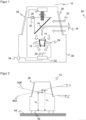
- FIG 1 shows a schematic sectional view through a laser scanner 10.
- a light transmitter 12 for example with a laser light source, generates a transmitted light beam 16 with the aid of a transmitting optics 14.
- the transmitted light beam 16 is emitted into a monitoring area 20 by means of a deflection unit 18.
- the transmitted light beam 16 can be at least partially surrounded by a transmitting tube (not shown).
- the transmitted light beam 16 is remitted by an object that may be present.
- the corresponding received light 22 returns to the laser scanner 10 and is detected by a light receiver 26 via the deflection unit 18 using a receiving optics 24.
- the receiving optics 24 is preferably a single converging lens, but additional lenses and other optical elements can be added.
- the light receiver 26 has, for example, at least one photodiode or, for greater sensitivity, an avalanche photodiode (APD) or an arrangement with at least one single photon avalanche diode (SPAD, SiPM).
- the deflection unit 18 is set into a continuous rotary motion at a scanning frequency by a motor 28. As a result, the transmitted light beam 16 scans a plane during each scanning period, i.e. a complete revolution at the scanning frequency.
- An angle measuring unit 30 is arranged on the outer circumference of the deflection unit 18 in order to detect the respective angular position of the deflection unit 18.
- the angle measuring unit 30 is formed here, for example, by a reticle disk as an angle measuring embodiment and a forked light barrier as a scanner.
- a control and evaluation unit 32 is connected to the light transmitter 12, the light receiver 26, the motor 28 and the angle measuring unit 30. By determining the light travel time between the emission of the transmitted light beam 16 and the reception of remitted received light 22, the distance of a scanned object from the laser scanner 10 is determined using the speed of light. The respective angular position at which the transmitted light beam 16 was emitted is known to the evaluation unit from the angle measuring unit 30.
- the interface 34 can be used for parameterization or other data exchange between the laser scanner 10 and the outside world.
- the interface 34 can be designed for communication in one or more conventional protocols, such as IO-Link, Ethernet, Profibus, USB3, Bluetooth, WLAN, LTE, 5G and many others.
- the interface 34 can be designed to be safe, in particular a safe output (OSSD, Output Signal Switching Device) for a safety-related shutdown signal when a protective field violation is detected.
- the laser scanner 10 is housed in a housing 36 which has a circumferential front panel 38.
- the light transmitter 12 and its transmitting optics 14 are located in a central opening of the receiving optics 24.
- the invention also includes alternative coaxial solutions, for example with a separate mirror area for the transmitted light beam 16 or with splitter mirrors, and also biaxial arrangements.
- the laser scanner 10 can use a rotating measuring head as a deflection unit instead of a rotating mirror, in which the light transmitter 12 and/or light receiver 26 rotate.
- Still other designs of a laser scanner 10 do not just scan a single scanning plane, but are multi-beam and thus designed as a multi-layer scanner. For the alignment to be explained shortly, one of the several scanning planes is then used, in particular a central scanning plane if available.
- a multi-layer scanner has several transmitter/receiver pairs that are offset in elevation from one another, whereby several light beams can be generated by a light source, for example by means of beam splitters or as a VCSEL array, and/or received in a matrix or, specifically, SPAD array.
- the invention is described using a laser scanner 10 as an example. However, it also includes other optoelectronic sensors, for example a light sensor whose scanning beam is to be aligned, a light grid with a large number of parallel detection beams or a 2D or 3D camera with alignment of its field of view. It also includes sensors that do not use an optical sensor principle. First of all, a radar should be mentioned, which also scans a scanning plane, even if this may be somewhat less clearly defined in elevation. Other sensors that are not exhaustively mentioned are ultrasonic sensors, capacitive, inductive or magnetic sensors, all of which, depending on the design and application of a require more or less precise alignment.
- the sensor according to the invention can be designed as a safety sensor in the sense of the standards mentioned in the introduction, in particular as a safety laser scanner, and can be used in safety technology to prevent accidents, for example by monitoring protective fields or evaluating the distance and speed of an object in the vicinity of a source of danger (speed and separation).
- the laser scanner 10 of the Figure 1 is a complete sensor, and the alignment of its housing 36 with respect to the outside, in particular a mounting surface, wall or the like, is explained below using this example.
- the invention can also be used in such a way that a sensor module such as a receiver module or a transmitter-receiver module is mounted in a sensor housing with high precision alignment.
- the reference surface is then not on the outside, but a wall or a reference surface of the sensor housing connected to it.
- the alignment principle in all variants is the same, thus transferable in an analogous manner, and is therefore not described separately.
- FIG 2 shows a schematic representation of a laser scanner 10 with illustration of two different scanning planes 40A-B due to manufacturing tolerances. Only the outer contours of a laser scanner 10 are shown below, for the other elements, please refer to the explanations of Figure 1
- the laser scanner 10 is arranged with a first outer wall 42 on a flat base surface 44. In Figure 2 This is shown in such a way that the laser scanner 10 is standing with its underside on the floor. Any other side of the laser scanner 10 can also be arranged on a base surface 44 with any other orientation, for example when mounted with the underside on the wall or with the top on the ceiling.
- the first outer wall 42 is the one that comes into contact with the flat base surface 44.
- the scanning plane 40A-B runs slightly differently in each laser scanner 10 as a result of component, installation or other tolerances, whereby Figure 2 This is clearly exaggerated. This is recorded by two quantities. Firstly, there is the orientation, which is characterized by a detection direction. This is because the inclination of the scanning plane 40A-B results from the direction of emission of the transmitted light beam 16. This is specified, for example, as an angle ⁇ A , ⁇ B to the base plane 44. Secondly, there is a detection height h A , hB , which is measured from the light emission area against a reference such as the lower end of the device.
- height is based on the Figure 2 shown upright orientation, with vertical mounting it is a lateral distance, corresponding with any inclination of the flat base surface 44, and all this is simply called height.
- the detection direction and detection height vary among laser scanners 10 of the same design, tolerances result in an individual detection direction and an individual detection height. These deviations require alignment and are not desired, but for cost reasons cannot be avoided at the source by reducing tolerances.
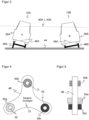
- Figure 3 shows a schematic representation of two laser scanners 10A-B, each with an individual intermediate piece 46A-B to compensate for the misalignment in the detection direction and/or detection height resulting from manufacturing tolerances.
- an intermediate piece 46A-B is manufactured individually, for example an intermediate plate that compensates for the inclination and height offset of the scanning planes 40A-B.
- the two scanning planes 40A-B now correspond to one another: They are at the same detection height and have the same, here horizontal, detection direction.
- the intermediate piece 46A-B forms the first outer wall 42 together with the actual, inner housing wall 48A-B. Thanks to the intermediate piece 46A-B, the first outer wall now has a three-dimensional contour with which the individual misalignment of the respective laser scanners 10A-B in the detection direction and/or detection height is individually compensated.
- the orientation of the scan plane 40A-B and/or the height of the light exit i.e. the individual detection direction or individual detection height
- the suitable intermediate piece 46A-B is manufactured individually if required.
- the intermediate piece 46 can be produced by removing material from a blank. Another possibility is an additive process such as 3D printing.
- the intermediate piece 46 By arranging the intermediate piece 46 between the inner housing wall 48A-B and the flat base surface 44, an individual adjustment or alignment is achieved. All laser scanners 10A-B of a product family can be brought to the same detection direction and/or detection height in this way. In contrast to, for example, adjusting screws or height-adjustable feet, this alignment can no longer be manipulated intentionally or inadvertently.
- the intermediate piece 46 can initially remain loose and only be inserted during assembly, or it can be attached to the laser scanner 10 in advance, again particularly during final production. Any fastening method is conceivable for this, such as hooks, magnetic force, screws, fitting, gluing, pressing or (laser) welding.
- the Figure 4 shows a top view and the Figure 5 shows a side view of an exemplary intermediate piece 46 with a compensating three-dimensional contour.
- three contact or support points 50a-c are sufficient according to the tripod principle. In other embodiments, there may be further contact points, contact surfaces or a full-surface contact.
- the support points 50a-c are widened to small areas, and inside them there is space for a respective screw hole 52 for fastening the laser scanner 10 to the flat base surface 44 by means of screws.
- the different heights of the support points 50a-c can be seen, which give the intermediate piece 46 the required three-dimensional contour.
- the intermediate piece 46 is adapted to the individually measured detection direction and/or detection height. Therefore, a clear assignment of the intermediate piece 46 to the associated laser scanner 10 is required. To make this easier, the intermediate piece 46 can be marked with a sufficiently clear identification code, for example a serial number 51 applied by laser inscription.
- the support points 50a-c usually have different heights, so that the correct orientation of the intermediate piece 46 is important. This can be ensured by shaping, alternatively by further markings, colors or structuring. No individualization is required to specify the orientation; rather, the three-dimensional contour can be applied for a specific orientation. Therefore, specifications for the correct orientation can be the same for all intermediate pieces 46 and, for example, can already be provided on a blank before the three-dimensional contour is applied.
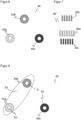
- Figure 6 shows a top view
- Figure 7 shows a side view of an alternative multi-part intermediate piece 46.
- these are the support points 50a-c of the Figures 4 to 5 , but without connecting material for a common intermediate piece 46.
- Such an intermediate piece 46 uses less material.
- a multi-part intermediate piece 46 should be attached to the laser scanner 10 before the laser scanner 10 is delivered to the operating site. Arranging a loose multi-part intermediate piece 46 between the first outer wall 42 and the flat base surface 44 only during assembly further increases the risk of confusion.
- Figure 8 shows a top view of another multi-part compensating intermediate piece 46.
- two support points 50a-b are assembled on a common component 53, only the third support point 50c forms a separate component.
- This is a hybrid form in which the advantages and disadvantages of a common component are taken into account in accordance with the Figures 4 and 5 and a multi-part component according to the Figures 6 and 7 appear in a weaker form each time.
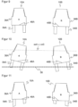
- the Figures 9 to 11 show another embodiment of the alignment of a laser scanner 10 by an individual compensating three-dimensional contour.
- Legs 54A-B with an oversize or excess length and thus a kind of material reserve are attached to the inner housing wall 48A-B. These legs 54A-B are therefore firmly connected to the laser scanner 10 at the beginning or in an early phase of production before individual adjustment.
- the first outer wall 42 is formed in this embodiment by the inner housing wall 48A-B and the legs 54A-B.
- the individual detection direction and/or individual detection height are measured, for example during final production.
- the legs 54A-B are now shortened in a mechanical rework according to the parting plane 56 shown, for example by a machining process or laser ablation.
- the parting plane 56 is merely an illustration of the required shortening and thus the three-dimensional contour to be achieved.
- the laser scanners 10A-B will assume the required alignment at the operating location with respect to a flat base surface 44 corresponding to the parting plane 56.
- Figure 11 shows the two laser scanners 10A-B once again in the delivery state. An intermediate piece 46 is not required in this embodiment.
- the Figure 12 illustrates another embodiment of the alignment, wherein Figure 13 a detailed view of the Figure 12 with the circle 58.
- the three-dimensional contour with support points of different heights is achieved by pressing pins 60 to different depths into a recess 62 in the inner housing wall 48.
- the pins 60 preferably originally have the same length, so they can be identical to one another, although pins of different lengths can also be used alternatively.
- the recess 62 can be dispensed with.
- the pins 60 can also be fixed at the correct depth, for example by gluing or welding.
- Figure 14 illustrates a very similar embodiment of the alignment, where Figure 15 a detailed view of the Figure 14 with the cutout marked with the circle 58.
- Threaded bushings 64 are pressed into the inner housing wall 48 at different depths. This also illustrates that pins 60 as well as threaded bushings 64 serve only as examples of elements that can be inserted at different depths in order to effectively produce different heights of the support points.
Landscapes
- Engineering & Computer Science (AREA)
- Physics & Mathematics (AREA)
- General Physics & Mathematics (AREA)
- Computer Networks & Wireless Communication (AREA)
- Radar, Positioning & Navigation (AREA)
- Remote Sensing (AREA)
- Computer Vision & Pattern Recognition (AREA)
- Electromagnetism (AREA)
- Measurement Of Optical Distance (AREA)
- Length Measuring Devices By Optical Means (AREA)
Applications Claiming Priority (1)
| Application Number | Priority Date | Filing Date | Title |
|---|---|---|---|
| DE102023106750.8A DE102023106750A1 (de) | 2023-03-17 | 2023-03-17 | Ausgerichteter Sensor |
Publications (2)
| Publication Number | Publication Date |
|---|---|
| EP4431981A1 true EP4431981A1 (fr) | 2024-09-18 |
| EP4431981B1 EP4431981B1 (fr) | 2025-09-10 |
Family
ID=89715865
Family Applications (1)
| Application Number | Title | Priority Date | Filing Date |
|---|---|---|---|
| EP24153800.8A Active EP4431981B1 (fr) | 2023-03-17 | 2024-01-24 | Capteur orienté |
Country Status (4)
| Country | Link |
|---|---|
| US (1) | US20240310487A1 (fr) |
| EP (1) | EP4431981B1 (fr) |
| CN (1) | CN118670253A (fr) |
| DE (1) | DE102023106750A1 (fr) |
Families Citing this family (1)
| Publication number | Priority date | Publication date | Assignee | Title |
|---|---|---|---|---|
| CN119417820B (zh) * | 2025-01-06 | 2025-08-08 | 杭州灵西机器人智能科技有限公司 | 基于机器视觉的方壳料框检测方法 |
Citations (10)
| Publication number | Priority date | Publication date | Assignee | Title |
|---|---|---|---|---|
| DE4340756A1 (de) | 1992-12-08 | 1994-06-09 | Sick Optik Elektronik Erwin | Laserabstandsermittlungsvorrichtung |
| DE10135109A1 (de) * | 2001-07-19 | 2003-02-06 | Conti Temic Microelectronic | Elektronische Baugruppe |
| US20040217899A1 (en) * | 2002-12-11 | 2004-11-04 | Hayato Kikuchi | Moving body transmitter and receiver axis adjusting system |
| EP1852646A2 (fr) | 2006-05-05 | 2007-11-07 | CSAV, Inc. | Montage de projecteur réglable muni d'un dispositif à libération rapide |
| US20090294619A1 (en) | 2008-05-29 | 2009-12-03 | Mike David | Projector mount with phillips screw driver angle adjustment |
| US20170006197A1 (en) * | 2015-06-30 | 2017-01-05 | Robert Bosch Gmbh | Camera housing for adjusting an optical system |
| DE202015106370U1 (de) | 2015-11-23 | 2017-02-24 | Sick Ag | Halterung |
| WO2022213786A1 (fr) * | 2021-04-07 | 2022-10-13 | 深圳市道通科技股份有限公司 | Dispositif de réglage de radar monté sur véhicule et dispositif radar monté sur véhicule |
| EP4137843A1 (fr) * | 2021-08-16 | 2023-02-22 | Jungheinrich Aktiengesellschaft | Suspension réglable pour un dispositif balayeur d'un chariot de manutention et combinaison d'une telle suspension avec un dispositif de balayage d'un chariot de manutention |
| US20230077077A1 (en) * | 2017-08-24 | 2023-03-09 | Topcon Corporation | 3-dimensional measuring device |
-
2023
- 2023-03-17 DE DE102023106750.8A patent/DE102023106750A1/de active Pending
-
2024
- 2024-01-24 EP EP24153800.8A patent/EP4431981B1/fr active Active
- 2024-02-22 CN CN202410198254.2A patent/CN118670253A/zh active Pending
- 2024-03-13 US US18/603,437 patent/US20240310487A1/en active Pending
Patent Citations (10)
| Publication number | Priority date | Publication date | Assignee | Title |
|---|---|---|---|---|
| DE4340756A1 (de) | 1992-12-08 | 1994-06-09 | Sick Optik Elektronik Erwin | Laserabstandsermittlungsvorrichtung |
| DE10135109A1 (de) * | 2001-07-19 | 2003-02-06 | Conti Temic Microelectronic | Elektronische Baugruppe |
| US20040217899A1 (en) * | 2002-12-11 | 2004-11-04 | Hayato Kikuchi | Moving body transmitter and receiver axis adjusting system |
| EP1852646A2 (fr) | 2006-05-05 | 2007-11-07 | CSAV, Inc. | Montage de projecteur réglable muni d'un dispositif à libération rapide |
| US20090294619A1 (en) | 2008-05-29 | 2009-12-03 | Mike David | Projector mount with phillips screw driver angle adjustment |
| US20170006197A1 (en) * | 2015-06-30 | 2017-01-05 | Robert Bosch Gmbh | Camera housing for adjusting an optical system |
| DE202015106370U1 (de) | 2015-11-23 | 2017-02-24 | Sick Ag | Halterung |
| US20230077077A1 (en) * | 2017-08-24 | 2023-03-09 | Topcon Corporation | 3-dimensional measuring device |
| WO2022213786A1 (fr) * | 2021-04-07 | 2022-10-13 | 深圳市道通科技股份有限公司 | Dispositif de réglage de radar monté sur véhicule et dispositif radar monté sur véhicule |
| EP4137843A1 (fr) * | 2021-08-16 | 2023-02-22 | Jungheinrich Aktiengesellschaft | Suspension réglable pour un dispositif balayeur d'un chariot de manutention et combinaison d'une telle suspension avec un dispositif de balayage d'un chariot de manutention |
Also Published As
| Publication number | Publication date |
|---|---|
| US20240310487A1 (en) | 2024-09-19 |
| DE102023106750A1 (de) | 2024-09-19 |
| EP4431981B1 (fr) | 2025-09-10 |
| CN118670253A (zh) | 2024-09-20 |
Similar Documents
| Publication | Publication Date | Title |
|---|---|---|
| EP3321628B1 (fr) | Dispositif de mesure de coordonnées doté d'un capteur optique et procédé correspondant | |
| EP2453254B1 (fr) | Dispositif de surveillance d'une porte doté d'un capteur 3D | |
| DE60304664T2 (de) | System zur Justage einer Achse einer auf einem beweglichen Körper montierten Sende- und Empfängereinheit | |
| EP2732309B1 (fr) | Dispositif de mesure optique pour un véhicule, appareil d'assistance au conducteur comprenant un tel dispositif de mesure ainsi que véhicule équipé d'un dispositif de mesure correspondant | |
| EP3517999A1 (fr) | Capteur optoélectronique et procédé de détection d'objets | |
| EP1927867A1 (fr) | Capteur optoélectronique à plusieurs plans et procédé de détection d'objets | |
| DE102014105781B4 (de) | Optoelektronischer Sensor und Verfahren zur Erfassung von Messinformationen aus einem Überwachungsbereich | |
| EP3176606B1 (fr) | Procédé destiné à l'alignement d'un scanner laser | |
| EP3236204B1 (fr) | Laser rotatif nivelable et son utilisation dans la mesure de machines-outils | |
| DE102016118983B3 (de) | Stativkopf | |
| EP2378309A1 (fr) | Capteur optoélectronique et procédé de production d'informations sur des objets dans une zone de surveillance | |
| EP4431981B1 (fr) | Capteur orienté | |
| EP3203263A1 (fr) | Capteur optoélectronique et procédé destiné à la saisie d'objets | |
| EP3086094A1 (fr) | Émetteur de commande manuelle, unité de commande doté d'un émetteur de commande manuelle et machine de travail ou engin | |
| EP3640667A1 (fr) | Capteur optoélectronique et procédé de détection d'objets | |
| DE102021111949B4 (de) | Vorrichtung zur scannenden Messung des Abstands zu einem Objekt | |
| EP2732305B1 (fr) | Dispositif de mesure optique pour un véhicule, dispositif d'aide à la conduite comprenant un dispositif de mesure de ce type et véhicule équipé d'un dispositif de mesure correspondant | |
| DE102012112615B3 (de) | Optoelektronischer Sensor und Verfahren zur Veränderung der Messrichtung eines optoelektronischen Sensors | |
| EP2375266A1 (fr) | Capteur optoélectronique et procédé de sécurisation | |
| WO2008058785A1 (fr) | Procédé d'ajustement d'une antenne directionnelle d'un système radar et système radar en vue de la mise en œuvre du procédé | |
| DE202023101345U1 (de) | Ausgerichteter Sensor | |
| EP2395372A1 (fr) | Scanner de sécurité | |
| WO2005071434A1 (fr) | Procede et dispositif pour realiser l'alignement angulaire d'un capteur dans un vehicule automobile | |
| EP3933433B1 (fr) | Dispositif capteur et procédé d'alignement | |
| EP4464977A1 (fr) | Procédé, produit programme informatique, support de données et utilisation |
Legal Events
| Date | Code | Title | Description |
|---|---|---|---|
| PUAI | Public reference made under article 153(3) epc to a published international application that has entered the european phase |
Free format text: ORIGINAL CODE: 0009012 |
|
| STAA | Information on the status of an ep patent application or granted ep patent |
Free format text: STATUS: THE APPLICATION HAS BEEN PUBLISHED |
|
| STAA | Information on the status of an ep patent application or granted ep patent |
Free format text: STATUS: REQUEST FOR EXAMINATION WAS MADE |
|
| AK | Designated contracting states |
Kind code of ref document: A1 Designated state(s): AL AT BE BG CH CY CZ DE DK EE ES FI FR GB GR HR HU IE IS IT LI LT LU LV MC ME MK MT NL NO PL PT RO RS SE SI SK SM TR |
|
| 17P | Request for examination filed |
Effective date: 20240826 |
|
| RBV | Designated contracting states (corrected) |
Designated state(s): AL AT BE BG CH CY CZ DE DK EE ES FI FR GB GR HR HU IE IS IT LI LT LU LV MC ME MK MT NL NO PL PT RO RS SE SI SK SM TR |
|
| STAA | Information on the status of an ep patent application or granted ep patent |
Free format text: STATUS: EXAMINATION IS IN PROGRESS |
|
| 17Q | First examination report despatched |
Effective date: 20250403 |
|
| GRAP | Despatch of communication of intention to grant a patent |
Free format text: ORIGINAL CODE: EPIDOSNIGR1 |
|
| STAA | Information on the status of an ep patent application or granted ep patent |
Free format text: STATUS: GRANT OF PATENT IS INTENDED |
|
| INTG | Intention to grant announced |
Effective date: 20250701 |
|
| GRAS | Grant fee paid |
Free format text: ORIGINAL CODE: EPIDOSNIGR3 |
|
| GRAA | (expected) grant |
Free format text: ORIGINAL CODE: 0009210 |
|
| STAA | Information on the status of an ep patent application or granted ep patent |
Free format text: STATUS: THE PATENT HAS BEEN GRANTED |
|
| AK | Designated contracting states |
Kind code of ref document: B1 Designated state(s): AL AT BE BG CH CY CZ DE DK EE ES FI FR GB GR HR HU IE IS IT LI LT LU LV MC ME MK MT NL NO PL PT RO RS SE SI SK SM TR |
|
| REG | Reference to a national code |
Ref country code: GB Ref legal event code: FG4D Free format text: NOT ENGLISH |
|
| REG | Reference to a national code |
Ref country code: CH Ref legal event code: EP |
|
| REG | Reference to a national code |
Ref country code: DE Ref legal event code: R096 Ref document number: 502024000212 Country of ref document: DE |
|
| REG | Reference to a national code |
Ref country code: IE Ref legal event code: FG4D Free format text: LANGUAGE OF EP DOCUMENT: GERMAN |
|
| PG25 | Lapsed in a contracting state [announced via postgrant information from national office to epo] |
Ref country code: NO Free format text: LAPSE BECAUSE OF FAILURE TO SUBMIT A TRANSLATION OF THE DESCRIPTION OR TO PAY THE FEE WITHIN THE PRESCRIBED TIME-LIMIT Effective date: 20251210 |
|
| REG | Reference to a national code |
Ref country code: LT Ref legal event code: MG9D |
|
| PG25 | Lapsed in a contracting state [announced via postgrant information from national office to epo] |
Ref country code: FI Free format text: LAPSE BECAUSE OF FAILURE TO SUBMIT A TRANSLATION OF THE DESCRIPTION OR TO PAY THE FEE WITHIN THE PRESCRIBED TIME-LIMIT Effective date: 20250910 |
|
| REG | Reference to a national code |
Ref country code: NL Ref legal event code: MP Effective date: 20250910 |
|
| PG25 | Lapsed in a contracting state [announced via postgrant information from national office to epo] |
Ref country code: HR Free format text: LAPSE BECAUSE OF FAILURE TO SUBMIT A TRANSLATION OF THE DESCRIPTION OR TO PAY THE FEE WITHIN THE PRESCRIBED TIME-LIMIT Effective date: 20250910 |
|
| PG25 | Lapsed in a contracting state [announced via postgrant information from national office to epo] |
Ref country code: GR Free format text: LAPSE BECAUSE OF FAILURE TO SUBMIT A TRANSLATION OF THE DESCRIPTION OR TO PAY THE FEE WITHIN THE PRESCRIBED TIME-LIMIT Effective date: 20251211 |
|
| PG25 | Lapsed in a contracting state [announced via postgrant information from national office to epo] |
Ref country code: SE Free format text: LAPSE BECAUSE OF FAILURE TO SUBMIT A TRANSLATION OF THE DESCRIPTION OR TO PAY THE FEE WITHIN THE PRESCRIBED TIME-LIMIT Effective date: 20250910 |
|
| PG25 | Lapsed in a contracting state [announced via postgrant information from national office to epo] |
Ref country code: LV Free format text: LAPSE BECAUSE OF FAILURE TO SUBMIT A TRANSLATION OF THE DESCRIPTION OR TO PAY THE FEE WITHIN THE PRESCRIBED TIME-LIMIT Effective date: 20250910 |
|
| PG25 | Lapsed in a contracting state [announced via postgrant information from national office to epo] |
Ref country code: BG Free format text: LAPSE BECAUSE OF FAILURE TO SUBMIT A TRANSLATION OF THE DESCRIPTION OR TO PAY THE FEE WITHIN THE PRESCRIBED TIME-LIMIT Effective date: 20250910 Ref country code: PL Free format text: LAPSE BECAUSE OF FAILURE TO SUBMIT A TRANSLATION OF THE DESCRIPTION OR TO PAY THE FEE WITHIN THE PRESCRIBED TIME-LIMIT Effective date: 20250910 |
|
| PG25 | Lapsed in a contracting state [announced via postgrant information from national office to epo] |
Ref country code: RS Free format text: LAPSE BECAUSE OF FAILURE TO SUBMIT A TRANSLATION OF THE DESCRIPTION OR TO PAY THE FEE WITHIN THE PRESCRIBED TIME-LIMIT Effective date: 20251210 |
|
| PG25 | Lapsed in a contracting state [announced via postgrant information from national office to epo] |
Ref country code: ES Free format text: LAPSE BECAUSE OF FAILURE TO SUBMIT A TRANSLATION OF THE DESCRIPTION OR TO PAY THE FEE WITHIN THE PRESCRIBED TIME-LIMIT Effective date: 20250910 |
|
| PG25 | Lapsed in a contracting state [announced via postgrant information from national office to epo] |
Ref country code: NL Free format text: LAPSE BECAUSE OF FAILURE TO SUBMIT A TRANSLATION OF THE DESCRIPTION OR TO PAY THE FEE WITHIN THE PRESCRIBED TIME-LIMIT Effective date: 20250910 |
|
| PG25 | Lapsed in a contracting state [announced via postgrant information from national office to epo] |
Ref country code: SM Free format text: LAPSE BECAUSE OF FAILURE TO SUBMIT A TRANSLATION OF THE DESCRIPTION OR TO PAY THE FEE WITHIN THE PRESCRIBED TIME-LIMIT Effective date: 20250910 |
|
| PGFP | Annual fee paid to national office [announced via postgrant information from national office to epo] |
Ref country code: DE Payment date: 20260120 Year of fee payment: 3 |
|
| PGFP | Annual fee paid to national office [announced via postgrant information from national office to epo] |
Ref country code: AT Payment date: 20260301 Year of fee payment: 3 |
|
| PG25 | Lapsed in a contracting state [announced via postgrant information from national office to epo] |
Ref country code: IT Free format text: LAPSE BECAUSE OF FAILURE TO SUBMIT A TRANSLATION OF THE DESCRIPTION OR TO PAY THE FEE WITHIN THE PRESCRIBED TIME-LIMIT Effective date: 20250910 |
|
| PG25 | Lapsed in a contracting state [announced via postgrant information from national office to epo] |
Ref country code: IS Free format text: LAPSE BECAUSE OF FAILURE TO SUBMIT A TRANSLATION OF THE DESCRIPTION OR TO PAY THE FEE WITHIN THE PRESCRIBED TIME-LIMIT Effective date: 20260110 |
|
| PGFP | Annual fee paid to national office [announced via postgrant information from national office to epo] |
Ref country code: FR Payment date: 20260121 Year of fee payment: 3 |
|
| PG25 | Lapsed in a contracting state [announced via postgrant information from national office to epo] |
Ref country code: CZ Free format text: LAPSE BECAUSE OF FAILURE TO SUBMIT A TRANSLATION OF THE DESCRIPTION OR TO PAY THE FEE WITHIN THE PRESCRIBED TIME-LIMIT Effective date: 20250910 Ref country code: PT Free format text: LAPSE BECAUSE OF FAILURE TO SUBMIT A TRANSLATION OF THE DESCRIPTION OR TO PAY THE FEE WITHIN THE PRESCRIBED TIME-LIMIT Effective date: 20260112 |
|
| PG25 | Lapsed in a contracting state [announced via postgrant information from national office to epo] |
Ref country code: EE Free format text: LAPSE BECAUSE OF FAILURE TO SUBMIT A TRANSLATION OF THE DESCRIPTION OR TO PAY THE FEE WITHIN THE PRESCRIBED TIME-LIMIT Effective date: 20250910 Ref country code: SK Free format text: LAPSE BECAUSE OF FAILURE TO SUBMIT A TRANSLATION OF THE DESCRIPTION OR TO PAY THE FEE WITHIN THE PRESCRIBED TIME-LIMIT Effective date: 20250910 |