EP4138286A1 - Magnetgetriebemotor - Google Patents
Magnetgetriebemotor Download PDFInfo
- Publication number
- EP4138286A1 EP4138286A1 EP20931637.1A EP20931637A EP4138286A1 EP 4138286 A1 EP4138286 A1 EP 4138286A1 EP 20931637 A EP20931637 A EP 20931637A EP 4138286 A1 EP4138286 A1 EP 4138286A1
- Authority
- EP
- European Patent Office
- Prior art keywords
- spacers
- divisional
- magnetic
- rotor
- speed rotor
- Prior art date
- Legal status (The legal status is an assumption and is not a legal conclusion. Google has not performed a legal analysis and makes no representation as to the accuracy of the status listed.)
- Granted
Links
Images
Classifications
-
- H—ELECTRICITY
- H02—GENERATION; CONVERSION OR DISTRIBUTION OF ELECTRIC POWER
- H02K—DYNAMO-ELECTRIC MACHINES
- H02K49/00—Dynamo-electric clutches; Dynamo-electric brakes
- H02K49/10—Dynamo-electric clutches; Dynamo-electric brakes of the permanent-magnet type
- H02K49/102—Magnetic gearings, i.e. assembly of gears, linear or rotary, by which motion is magnetically transferred without physical contact
-
- H—ELECTRICITY
- H02—GENERATION; CONVERSION OR DISTRIBUTION OF ELECTRIC POWER
- H02K—DYNAMO-ELECTRIC MACHINES
- H02K7/00—Arrangements for handling mechanical energy structurally associated with dynamo-electric machines, e.g. structural association with mechanical driving motors or auxiliary dynamo-electric machines
- H02K7/10—Structural association with clutches, brakes, gears, pulleys or mechanical starters
- H02K7/11—Structural association with clutches, brakes, gears, pulleys or mechanical starters with dynamo-electric clutches
-
- H—ELECTRICITY
- H02—GENERATION; CONVERSION OR DISTRIBUTION OF ELECTRIC POWER
- H02K—DYNAMO-ELECTRIC MACHINES
- H02K1/00—Details of the magnetic circuit
- H02K1/06—Details of the magnetic circuit characterised by the shape, form or construction
- H02K1/22—Rotating parts of the magnetic circuit
- H02K1/27—Rotor cores with permanent magnets
-
- H—ELECTRICITY
- H02—GENERATION; CONVERSION OR DISTRIBUTION OF ELECTRIC POWER
- H02K—DYNAMO-ELECTRIC MACHINES
- H02K9/00—Arrangements for cooling or ventilating
- H02K9/22—Arrangements for cooling or ventilating by solid heat conducting material embedded in, or arranged in contact with, the stator or rotor, e.g. heat bridges
- H02K9/223—Heat bridges
-
- H—ELECTRICITY
- H02—GENERATION; CONVERSION OR DISTRIBUTION OF ELECTRIC POWER
- H02N—ELECTRIC MACHINES NOT OTHERWISE PROVIDED FOR
- H02N15/00—Holding or levitation devices using magnetic attraction or repulsion, not otherwise provided for
-
- Y—GENERAL TAGGING OF NEW TECHNOLOGICAL DEVELOPMENTS; GENERAL TAGGING OF CROSS-SECTIONAL TECHNOLOGIES SPANNING OVER SEVERAL SECTIONS OF THE IPC; TECHNICAL SUBJECTS COVERED BY FORMER USPC CROSS-REFERENCE ART COLLECTIONS [XRACs] AND DIGESTS
- Y02—TECHNOLOGIES OR APPLICATIONS FOR MITIGATION OR ADAPTATION AGAINST CLIMATE CHANGE
- Y02E—REDUCTION OF GREENHOUSE GAS [GHG] EMISSIONS, RELATED TO ENERGY GENERATION, TRANSMISSION OR DISTRIBUTION
- Y02E10/00—Energy generation through renewable energy sources
- Y02E10/70—Wind energy
- Y02E10/72—Wind turbines with rotation axis in wind direction
-
- Y—GENERAL TAGGING OF NEW TECHNOLOGICAL DEVELOPMENTS; GENERAL TAGGING OF CROSS-SECTIONAL TECHNOLOGIES SPANNING OVER SEVERAL SECTIONS OF THE IPC; TECHNICAL SUBJECTS COVERED BY FORMER USPC CROSS-REFERENCE ART COLLECTIONS [XRACs] AND DIGESTS
- Y02—TECHNOLOGIES OR APPLICATIONS FOR MITIGATION OR ADAPTATION AGAINST CLIMATE CHANGE
- Y02T—CLIMATE CHANGE MITIGATION TECHNOLOGIES RELATED TO TRANSPORTATION
- Y02T10/00—Road transport of goods or passengers
- Y02T10/60—Other road transportation technologies with climate change mitigation effect
- Y02T10/64—Electric machine technologies in electromobility
Definitions
- the present invention relates to a magnetic-geared motor.
- a magnetic-geared motor having a magnetic speed reducer and a motor integrated with each other is used.
- the magnetic-geared motor is composed of a low-speed rotor, a high-speed rotor provided coaxially with the low-speed rotor, and a stator having a stator coil and a permanent magnet.
- the low-speed rotor rotates in conjunction with a wind mill and induced power is generated in the stator coil through rotation of the low-speed rotor, whereby power generation is performed.
- a plurality of magnetic pole pieces are disposed in the circumferential direction.
- One magnetic pole piece is formed by stacking a plurality of thin-plate-shaped electromagnetic steel sheets in the axial direction.
- a method for fixing the magnetic pole pieces in the axial direction disclosed is a method in which metal bar-shaped fastening members are disposed in the circumferential direction between a plurality of magnetic pole pieces, and metal end plates are provided at both ends in the axial direction. The end plates at both ends are fastened in the axial direction by the fastening members, whereby the magnetic pole pieces are fixed in the axial direction.
- a current loop that circulates between the metal fastening members and the end plates is formed, and induced current is generated in the current loop during rotation.
- the induced current increases, so that power loss in the magnetic-geared motor increases.
- Patent Document 1 Japanese Patent JP 5 286 373 B2
- the present invention has been made to solve the above problem, and an object of the present invention is to provide a magnetic-geared motor that can suppress eddy current flowing inside a fastening member and reduce power loss.
- a magnetic-geared motor includes: a stator including a stator coil and a stator permanent magnet; a first rotor provided rotatably relative to the stator with a first gap from the stator, the first rotor including a plurality of magnetic pole pieces disposed so as to be arranged in a circumferential direction and a plurality of spacers made of nonmagnetic metal and respectively disposed between the plurality of magnetic pole pieces; and a second rotor provided coaxially with the first rotor with a second gap from the first rotor, the second rotor including a plurality of rotor permanent magnets disposed so as to be arranged in the circumferential direction, wherein each spacer is composed of a plurality of divisional spacers disposed apart from each other in an axial direction, and a plurality of fastening tools for fastening the plurality of divisional spacers in the axial direction, and the divisional spacers and the fastening tools are electrically insulated from each other
- the magnetic-geared motor according to the present invention includes the spacers composed of the plurality of divisional spacers disposed apart from each other in the axial direction and the plurality of fastening tools for fastening the plurality of divisional spacers in the axial direction, and the divisional spacers and the fastening tools are electrically insulated from each other. Since the spacer which is a fastening member and the fastening tool are electrically insulated from each other, eddy current flowing inside the fastening member is divided into a plurality of eddy currents. As a result, eddy current flowing inside the fastening member can be suppressed and power loss can be reduced.
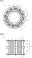
- FIG. 1 is a schematic sectional view of a magnetic-geared motor according to Embodiment 1.
- FIG. 1 is a schematic sectional view along a plane perpendicular to the axial direction of the magnetic-geared motor.
- the magnetic-geared motor 1 of the present embodiment includes a stator 10, a low-speed rotor 20 provided rotatably relative to the stator 10 with a gap from the stator 10, and a high-speed rotor 30 provided coaxially with the low-speed rotor 20 with a gap therefrom.
- the stator 10, the low-speed rotor 20, and the high-speed rotor 30 have cylindrical shapes and are disposed coaxially with each other.
- the stator 10, the low-speed rotor 20, and the high-speed rotor 30 are disposed in this order from the outer diameter side.
- the stator 10 includes a stator core 11 having a cylindrical shape, a stator coil 12, and a stator permanent magnet 13.
- the stator core 11 has 12 teeth 14 protruding to the inner circumferential side, and 12 slots 15 are formed between the teeth 14.
- the stator coil 12 and the stator permanent magnet 13 are disposed in each slot 15.
- the low-speed rotor 20 having a cylindrical shape includes a plurality of magnetic pole pieces 21 disposed so as to be arranged in the circumferential direction, and a plurality of nonmagnetic metal spacers 22 disposed between the plurality of magnetic pole pieces 21. 17 magnetic pole pieces 21 and 17 spacers 22 are provided.
- the high-speed rotor 30 includes a high-speed rotor core 31 having a cylindrical shape, and 10 rotor permanent magnets 32 disposed so as to be arranged in the circumferential direction on the outer circumferential surface of the high-speed rotor core 31.
- the magnetic-geared motor 1 of the present embodiment is a so-called 10-pole 12-slot magnetic-geared motor.
- the speed increase ratio determined by the number of magnetic pole pieces/the number of pole pairs is 17/5, i.e., 3.4, and the high-speed rotor 30 rotates at 3.4 times the rotation speed of the low-speed rotor 20.
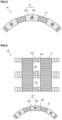
- FIG. 2 is a side view of the low-speed rotor 20 in the present embodiment.
- FIG. 2 is a side view when the magnetic-geared motor 1 is seen from the inner diameter side.
- the vertical direction is the axial direction of the magnetic-geared motor 1
- the horizontal direction is the circumferential direction.
- the low-speed rotor 20 includes the plurality of magnetic pole pieces 21 and the plurality of nonmagnetic metal spacers 22 disposed so as to be arranged in the circumferential direction.
- One magnetic pole piece 21 is formed by stacking a plurality of thin-plate-shaped electromagnetic steel sheets in the axial direction.
- a material of the spacer 22 nonmagnetic stainless steel, titanium, aluminum, brass, copper, or the like may be used.
- the spacer 22 is composed of a plurality of divisional spacers 22a disposed apart from each other in the axial direction, and a plurality of fastening tools 22b for fastening the plurality of divisional spacers 22a in the axial direction.
- a fastening method using screws may be used.
- the plurality of divisional spacers 22a are in contact with the magnetic pole pieces 21 in the circumferential direction.
- Clampers 23 having an annular shape are disposed at both ends in the axial direction of the low-speed rotor 20.
- the fastening tools 22b at both ends in the axial direction fasten the plurality of divisional spacers 22a with the clampers 23 therebetween.
- the clampers 23 fix the electromagnetic steel sheets stacked as the magnetic pole pieces 21, in the stacking direction.
- FIG. 3 is a top view of the low-speed rotor 20 in the present embodiment.
- the clampers 23 are not shown.
- the low-speed rotor 20 is formed in a cylindrical shape by the plurality of magnetic pole pieces 21 and the plurality of spacers 22 disposed so as to be arranged in the circumferential direction.
- the divisional spacer 22a and the fastening tool 22b are electrically insulated from each other.
- a sheet-shaped insulation member may be inserted between contact surfaces of the divisional spacer 22a and the fastening tool 22b.
- a silicone rubber film may be used as the sheet-shaped insulation member.
- insulation treatment may be performed on the surface of at least one of the divisional spacer 22a and the fastening tool 22b.
- insulation varnish may be applied to the surface of the metal member, or insulating ceramic or resin may be sprayed on the surface of the metal member.
- the spacer is formed by the plurality of divisional spacers 22a disposed apart from each other and the plurality of fastening tools 22b for fastening the plurality of divisional spacers 22a in the axial direction. Therefore, the sum of the axial-direction lengths of the plurality of fastening tools 22b is greater than the sum of the axial-direction lengths of the plurality of divisional spacers 22a.
- eddy current induced inside the spacer 22 which is a fastening member occurs as divided eddy currents at the respective insides of the divisional spacer 22a and the fastening tool 22b. This is because the divisional spacer 22a and the fastening tool 22b are electrically insulated from each other. Therefore, the eddy currents induced in the spacer 22 do not form one large loop that is long in the axial direction.
- the magnetic-geared motor of the present embodiment can suppress power loss due to eddy current.
- the configuration in which the stator 10, the low-speed rotor 20, and the high-speed rotor 30 are provided in this order from the outer diameter side, has been shown.
- the present invention is not limited to this configuration.
- the magnetic-geared motor of the present embodiment is not limited to a 10-pole 12-slot magnetic-geared motor.
- the electromagnetic steel sheets stacked as the magnetic pole pieces 21 are fixed in the stacking direction, using the clampers 23.
- the stacked electromagnetic steel sheets may be fixed in the stacking direction by swaging. In this case, the clampers 23 may be eliminated.
- a magnetic-geared motor used as an electric generator of a wind power generation device has a large size with a diameter of several meters. Therefore, a plurality of separated segments of a rotor may be manufactured, and at the time of instalment, the segments may be integrated to form the rotor.
- FIG. 4 is a schematic view of a low-speed rotor according to Embodiment 2.
- the upper view is a side view of the low-speed rotor in the present embodiment
- the lower view is a top view thereof.
- the fastening tools and the clampers are not shown.
- the clampers are not shown.
- the spacers 22 disposed in the circumferential direction for example, the spacers 22 at four positions away from each other by 90 degrees are configured to be separable from each other in the circumferential direction.
- the plurality of divisional spacers 22a arranged in the axial direction in one spacer 22 are configured to be separable to the upper and lower sides at circumferential-direction division planes 22c so that the low-speed rotor 20 can be separated in the circumferential direction.
- the low-speed rotor 20 configured as described above can be separated into a plurality of segments.
- the plurality of segments are fastened in the circumferential direction by the fastening tools 22b, thus forming the low-speed rotor 20.
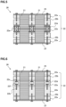
- FIG. 5 is a side view of a low-speed rotor according to Embodiment 3.
- the low-speed rotor 20 of the present embodiment is configured to be separable into a plurality of segments in the axial direction.
- the divisional spacers 22a arranged in the circumferential direction are configured to be separable to the upper and lower sides at an axial-direction division plane 22d so that the divisional spacers 22a can be separated in the axial direction.
- the divisional spacers 22a separable in the axial direction are provided to all the spacers 22.
- the magnetic pole pieces 21 are also configured to be separable in the axial direction at the axial-direction division plane 22d.
- the low-speed rotor 20 configured as described above can be separated into two segments in the axial direction. As shown in FIG. 5 , the two segments form the low-speed rotor 20 by fastening the separated divisional spacers 22a in the axial direction using second fastening tools 22e.
- FIG. 6 is a side view of another low-speed rotor according to Embodiment 3.
- a cavity 22f is formed in one of the divisional spacers 22a separable at the axial-direction division surface 22d.
- the separated divisional spacers 22a are fastened by the second fastening tool 22e.
- the low-speed rotor is separated into two segments in the axial direction.
- the low-speed rotor may be separated into three or more segments in the axial direction.
- FIG. 7 is a schematic view of a low-speed rotor according to Embodiment 4.
- the upper view is a side view of the low-speed rotor in the present embodiment
- the lower view is a top view thereof.
- the divisional spacers 22a disposed so as to be arranged in the circumferential direction are integrated with each other on the inner diameter side and the outer diameter side.
- the low-speed rotor 20 configured as described above, there is no step between the divisional spacer 22a and the magnetic pole piece 21, so that the air resistance of the low-speed rotor 20 can be reduced. As a result, rotation efficiency of the low-speed rotor 20 is improved and noise can be reduced. In addition, since rigidity of the divisional spacers 22a can be increased, rigidity of the entire low-speed rotor 20 also increases. Further, when the magnetic-geared motor is assembled, the low-speed rotor is inserted between the stator and the high-speed rotor.
- the divisional spacers 22a are integrated with each other on the inner diameter side and the outer diameter side.
- nonmagnetic metal thin plates which are separate parts from the divisional spacers 22a may be disposed between the divisional spacers 22a.
- the nonmagnetic metal thin plates may be detached after assembly.
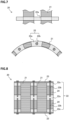
- FIG. 8 is a side view of a low-speed rotor according to Embodiment 5.
- the spacer is provided with a heat dissipation member.
- nonmagnetic heat dissipation members 24 are provided between the plurality of divisional spacers 22a disposed apart from each other in the axial direction. The heat dissipation members 24 are in contact with the magnetic pole pieces 21 and the divisional spacers 22a.
- a non-metal material e.g., resin having high thermal conductivity may be used.
- the weight of the low-speed rotor 20 increases.
- the material of the heat dissipation member 24 may have a hollow structure or a structure including a cutout.
Landscapes
- Engineering & Computer Science (AREA)
- Power Engineering (AREA)
- Chemical & Material Sciences (AREA)
- Combustion & Propulsion (AREA)
- Iron Core Of Rotating Electric Machines (AREA)
- Permanent Magnet Type Synchronous Machine (AREA)
- Connection Of Motors, Electrical Generators, Mechanical Devices, And The Like (AREA)
- Dynamo-Electric Clutches, Dynamo-Electric Brakes (AREA)
Applications Claiming Priority (1)
| Application Number | Priority Date | Filing Date | Title |
|---|---|---|---|
| PCT/JP2020/016672 WO2021210119A1 (ja) | 2020-04-16 | 2020-04-16 | 磁気ギアードモータ |
Publications (3)
| Publication Number | Publication Date |
|---|---|
| EP4138286A1 true EP4138286A1 (de) | 2023-02-22 |
| EP4138286A4 EP4138286A4 (de) | 2023-06-28 |
| EP4138286B1 EP4138286B1 (de) | 2024-06-26 |
Family
ID=78083978
Family Applications (1)
| Application Number | Title | Priority Date | Filing Date |
|---|---|---|---|
| EP20931637.1A Active EP4138286B1 (de) | 2020-04-16 | 2020-04-16 | Magnetgetriebemotor |
Country Status (6)
| Country | Link |
|---|---|
| US (1) | US12249889B2 (de) |
| EP (1) | EP4138286B1 (de) |
| JP (1) | JP7309049B2 (de) |
| CN (1) | CN115336151A (de) |
| DK (1) | DK4138286T3 (de) |
| WO (1) | WO2021210119A1 (de) |
Families Citing this family (2)
| Publication number | Priority date | Publication date | Assignee | Title |
|---|---|---|---|---|
| KR102769948B1 (ko) * | 2020-12-07 | 2025-02-17 | 현대자동차주식회사 | 마그네틱 기어 |
| JP2024087964A (ja) * | 2022-12-20 | 2024-07-02 | 三菱重工業株式会社 | 磁極片パネルユニット、磁極片回転子、および、磁気ギヤ電気機械 |
Family Cites Families (10)
| Publication number | Priority date | Publication date | Assignee | Title |
|---|---|---|---|---|
| CA2681713C (en) * | 2007-04-23 | 2012-11-27 | Honda Motor Co., Ltd. | Rotor for rotating electrical machine |
| JP4859751B2 (ja) | 2007-05-15 | 2012-01-25 | 本田技研工業株式会社 | 回転電機 |
| CN101897108B (zh) * | 2007-12-26 | 2013-04-10 | 本田技研工业株式会社 | 电动机以及旋转电机用转子 |
| JP2010017031A (ja) | 2008-07-04 | 2010-01-21 | Honda Motor Co Ltd | 回転電機用ロータ |
| JP5286373B2 (ja) * | 2011-01-28 | 2013-09-11 | 株式会社日立製作所 | 磁気歯車 |
| JP5423770B2 (ja) * | 2011-11-15 | 2014-02-19 | 株式会社デンソー | マルチギャップ型回転電機 |
| JP6403329B2 (ja) * | 2015-01-20 | 2018-10-10 | 株式会社Ihi | 磁気波動歯車装置 |
| GB2545154B (en) * | 2015-08-24 | 2021-12-01 | Magnomatics Ltd | Magnetically geared apparatus and a pole piece for such apparatus |
| JP6569396B2 (ja) | 2015-08-31 | 2019-09-04 | スズキ株式会社 | 回転電機 |
| JP7361344B2 (ja) * | 2019-02-26 | 2023-10-16 | パナソニックIpマネジメント株式会社 | 磁気ギアードモータ |
-
2020
- 2020-04-16 WO PCT/JP2020/016672 patent/WO2021210119A1/ja not_active Ceased
- 2020-04-16 CN CN202080099199.1A patent/CN115336151A/zh not_active Withdrawn
- 2020-04-16 EP EP20931637.1A patent/EP4138286B1/de active Active
- 2020-04-16 DK DK20931637.1T patent/DK4138286T3/da active
- 2020-04-16 US US17/791,905 patent/US12249889B2/en active Active
- 2020-04-16 JP JP2022514941A patent/JP7309049B2/ja active Active
Also Published As
| Publication number | Publication date |
|---|---|
| JPWO2021210119A1 (de) | 2021-10-21 |
| WO2021210119A1 (ja) | 2021-10-21 |
| US20220407402A1 (en) | 2022-12-22 |
| EP4138286B1 (de) | 2024-06-26 |
| CN115336151A (zh) | 2022-11-11 |
| EP4138286A4 (de) | 2023-06-28 |
| JP7309049B2 (ja) | 2023-07-14 |
| DK4138286T3 (da) | 2024-09-23 |
| US12249889B2 (en) | 2025-03-11 |
Similar Documents
| Publication | Publication Date | Title |
|---|---|---|
| US11784523B2 (en) | Multi-tunnel electric motor/generator | |
| US6844656B1 (en) | Electric multipole motor/generator with axial magnetic flux | |
| JP5851365B2 (ja) | 回転電機 | |
| US20160380496A1 (en) | Multi-tunnel electric motor/generator | |
| US12500498B2 (en) | Rotary electric machine | |
| JP5440423B2 (ja) | 回転電機 | |
| US7982352B2 (en) | Electrical motor/generator having a number of stator pole cores being larger than a number of rotor pole shoes | |
| EP2020662A2 (de) | Anordnung und Verfahren zur Magnetisierung von Permanentmagnetrotoren bei elektrischen Maschinen | |
| KR101979341B1 (ko) | 축방향 권선형 모터 | |
| EP2571142A1 (de) | Rotor mit einem eingebetteten permanentmagneten | |
| EP2124322B1 (de) | System und Vorrichtung mit Schenkelpolanker einer supraleitenden Maschine | |
| EP3050192A2 (de) | Rotor für eine elektrische maschine | |
| JPWO2019203076A1 (ja) | コイル及びそれを用いたモータ | |
| EP4138286B1 (de) | Magnetgetriebemotor | |
| US20180205302A1 (en) | Permanent magnet (pm) brushless machine with outer rotor | |
| JP2013059178A (ja) | 磁気ギア | |
| JP2020092585A (ja) | ハイブリッド界磁方式アキシャルエアギャップ型同期発電機ならび同期電動機に | |
| JP2002238194A (ja) | 永久磁石電動機の回転子構造 | |
| US9935512B2 (en) | Permanent magnet rotating electrical machine | |
| EP4383532B1 (de) | Magnetische spannungswellengetriebevorrichtung | |
| US11201528B2 (en) | Induction motor for use in drones | |
| US20170317541A1 (en) | Interior magnet rotary electric machine | |
| JP2018148675A (ja) | 回転電機のステータ | |
| WO2005050821A2 (en) | Generator with high efficiency | |
| TW201737596A (zh) | 軸流間隙型旋轉電機 |
Legal Events
| Date | Code | Title | Description |
|---|---|---|---|
| STAA | Information on the status of an ep patent application or granted ep patent |
Free format text: STATUS: THE INTERNATIONAL PUBLICATION HAS BEEN MADE |
|
| PUAI | Public reference made under article 153(3) epc to a published international application that has entered the european phase |
Free format text: ORIGINAL CODE: 0009012 |
|
| STAA | Information on the status of an ep patent application or granted ep patent |
Free format text: STATUS: REQUEST FOR EXAMINATION WAS MADE |
|
| 17P | Request for examination filed |
Effective date: 20221006 |
|
| AK | Designated contracting states |
Kind code of ref document: A1 Designated state(s): AL AT BE BG CH CY CZ DE DK EE ES FI FR GB GR HR HU IE IS IT LI LT LU LV MC MK MT NL NO PL PT RO RS SE SI SK SM TR |
|
| REG | Reference to a national code |
Ref country code: DE Ref legal event code: R079 Free format text: PREVIOUS MAIN CLASS: H02K0016020000 Ipc: H02K0007110000 Ref country code: DE Ref legal event code: R079 Ref document number: 602020033147 Country of ref document: DE Free format text: PREVIOUS MAIN CLASS: H02K0016020000 Ipc: H02K0007110000 |
|
| A4 | Supplementary search report drawn up and despatched |
Effective date: 20230531 |
|
| RIC1 | Information provided on ipc code assigned before grant |
Ipc: H02K 1/27 20220101ALI20230524BHEP Ipc: H02K 9/22 20060101ALI20230524BHEP Ipc: H02K 49/10 20060101ALI20230524BHEP Ipc: H02K 7/11 20060101AFI20230524BHEP |
|
| DAV | Request for validation of the european patent (deleted) | ||
| DAX | Request for extension of the european patent (deleted) | ||
| GRAP | Despatch of communication of intention to grant a patent |
Free format text: ORIGINAL CODE: EPIDOSNIGR1 |
|
| STAA | Information on the status of an ep patent application or granted ep patent |
Free format text: STATUS: GRANT OF PATENT IS INTENDED |
|
| INTG | Intention to grant announced |
Effective date: 20240318 |
|
| GRAS | Grant fee paid |
Free format text: ORIGINAL CODE: EPIDOSNIGR3 |
|
| GRAA | (expected) grant |
Free format text: ORIGINAL CODE: 0009210 |
|
| STAA | Information on the status of an ep patent application or granted ep patent |
Free format text: STATUS: THE PATENT HAS BEEN GRANTED |
|
| AK | Designated contracting states |
Kind code of ref document: B1 Designated state(s): AL AT BE BG CH CY CZ DE DK EE ES FI FR GB GR HR HU IE IS IT LI LT LU LV MC MK MT NL NO PL PT RO RS SE SI SK SM TR |
|
| REG | Reference to a national code |
Ref country code: GB Ref legal event code: FG4D |
|
| REG | Reference to a national code |
Ref country code: CH Ref legal event code: EP |
|
| REG | Reference to a national code |
Ref country code: DE Ref legal event code: R096 Ref document number: 602020033147 Country of ref document: DE |
|
| REG | Reference to a national code |
Ref country code: DK Ref legal event code: T3 Effective date: 20240918 |
|
| PG25 | Lapsed in a contracting state [announced via postgrant information from national office to epo] |
Ref country code: BG Free format text: LAPSE BECAUSE OF FAILURE TO SUBMIT A TRANSLATION OF THE DESCRIPTION OR TO PAY THE FEE WITHIN THE PRESCRIBED TIME-LIMIT Effective date: 20240626 |
|
| PG25 | Lapsed in a contracting state [announced via postgrant information from national office to epo] |
Ref country code: HR Free format text: LAPSE BECAUSE OF FAILURE TO SUBMIT A TRANSLATION OF THE DESCRIPTION OR TO PAY THE FEE WITHIN THE PRESCRIBED TIME-LIMIT Effective date: 20240626 Ref country code: FI Free format text: LAPSE BECAUSE OF FAILURE TO SUBMIT A TRANSLATION OF THE DESCRIPTION OR TO PAY THE FEE WITHIN THE PRESCRIBED TIME-LIMIT Effective date: 20240626 |
|
| REG | Reference to a national code |
Ref country code: LT Ref legal event code: MG9D |
|
| PG25 | Lapsed in a contracting state [announced via postgrant information from national office to epo] |
Ref country code: GR Free format text: LAPSE BECAUSE OF FAILURE TO SUBMIT A TRANSLATION OF THE DESCRIPTION OR TO PAY THE FEE WITHIN THE PRESCRIBED TIME-LIMIT Effective date: 20240927 |
|
| PG25 | Lapsed in a contracting state [announced via postgrant information from national office to epo] |
Ref country code: LV Free format text: LAPSE BECAUSE OF FAILURE TO SUBMIT A TRANSLATION OF THE DESCRIPTION OR TO PAY THE FEE WITHIN THE PRESCRIBED TIME-LIMIT Effective date: 20240626 |
|
| REG | Reference to a national code |
Ref country code: NL Ref legal event code: MP Effective date: 20240626 |
|
| PG25 | Lapsed in a contracting state [announced via postgrant information from national office to epo] |
Ref country code: NO Free format text: LAPSE BECAUSE OF FAILURE TO SUBMIT A TRANSLATION OF THE DESCRIPTION OR TO PAY THE FEE WITHIN THE PRESCRIBED TIME-LIMIT Effective date: 20240926 Ref country code: LV Free format text: LAPSE BECAUSE OF FAILURE TO SUBMIT A TRANSLATION OF THE DESCRIPTION OR TO PAY THE FEE WITHIN THE PRESCRIBED TIME-LIMIT Effective date: 20240626 Ref country code: HR Free format text: LAPSE BECAUSE OF FAILURE TO SUBMIT A TRANSLATION OF THE DESCRIPTION OR TO PAY THE FEE WITHIN THE PRESCRIBED TIME-LIMIT Effective date: 20240626 Ref country code: GR Free format text: LAPSE BECAUSE OF FAILURE TO SUBMIT A TRANSLATION OF THE DESCRIPTION OR TO PAY THE FEE WITHIN THE PRESCRIBED TIME-LIMIT Effective date: 20240927 Ref country code: FI Free format text: LAPSE BECAUSE OF FAILURE TO SUBMIT A TRANSLATION OF THE DESCRIPTION OR TO PAY THE FEE WITHIN THE PRESCRIBED TIME-LIMIT Effective date: 20240626 Ref country code: BG Free format text: LAPSE BECAUSE OF FAILURE TO SUBMIT A TRANSLATION OF THE DESCRIPTION OR TO PAY THE FEE WITHIN THE PRESCRIBED TIME-LIMIT Effective date: 20240626 Ref country code: RS Free format text: LAPSE BECAUSE OF FAILURE TO SUBMIT A TRANSLATION OF THE DESCRIPTION OR TO PAY THE FEE WITHIN THE PRESCRIBED TIME-LIMIT Effective date: 20240926 |
|
| PG25 | Lapsed in a contracting state [announced via postgrant information from national office to epo] |
Ref country code: NL Free format text: LAPSE BECAUSE OF FAILURE TO SUBMIT A TRANSLATION OF THE DESCRIPTION OR TO PAY THE FEE WITHIN THE PRESCRIBED TIME-LIMIT Effective date: 20240626 |
|
| REG | Reference to a national code |
Ref country code: AT Ref legal event code: MK05 Ref document number: 1698522 Country of ref document: AT Kind code of ref document: T Effective date: 20240626 |
|
| PG25 | Lapsed in a contracting state [announced via postgrant information from national office to epo] |
Ref country code: NL Free format text: LAPSE BECAUSE OF FAILURE TO SUBMIT A TRANSLATION OF THE DESCRIPTION OR TO PAY THE FEE WITHIN THE PRESCRIBED TIME-LIMIT Effective date: 20240626 |
|
| PG25 | Lapsed in a contracting state [announced via postgrant information from national office to epo] |
Ref country code: PT Free format text: LAPSE BECAUSE OF FAILURE TO SUBMIT A TRANSLATION OF THE DESCRIPTION OR TO PAY THE FEE WITHIN THE PRESCRIBED TIME-LIMIT Effective date: 20241028 |
|
| PG25 | Lapsed in a contracting state [announced via postgrant information from national office to epo] |
Ref country code: PT Free format text: LAPSE BECAUSE OF FAILURE TO SUBMIT A TRANSLATION OF THE DESCRIPTION OR TO PAY THE FEE WITHIN THE PRESCRIBED TIME-LIMIT Effective date: 20241028 |
|
| PG25 | Lapsed in a contracting state [announced via postgrant information from national office to epo] |
Ref country code: PL Free format text: LAPSE BECAUSE OF FAILURE TO SUBMIT A TRANSLATION OF THE DESCRIPTION OR TO PAY THE FEE WITHIN THE PRESCRIBED TIME-LIMIT Effective date: 20240626 |
|
| PG25 | Lapsed in a contracting state [announced via postgrant information from national office to epo] |
Ref country code: EE Free format text: LAPSE BECAUSE OF FAILURE TO SUBMIT A TRANSLATION OF THE DESCRIPTION OR TO PAY THE FEE WITHIN THE PRESCRIBED TIME-LIMIT Effective date: 20240626 |
|
| PG25 | Lapsed in a contracting state [announced via postgrant information from national office to epo] |
Ref country code: IS Free format text: LAPSE BECAUSE OF FAILURE TO SUBMIT A TRANSLATION OF THE DESCRIPTION OR TO PAY THE FEE WITHIN THE PRESCRIBED TIME-LIMIT Effective date: 20241026 Ref country code: AT Free format text: LAPSE BECAUSE OF FAILURE TO SUBMIT A TRANSLATION OF THE DESCRIPTION OR TO PAY THE FEE WITHIN THE PRESCRIBED TIME-LIMIT Effective date: 20240626 |
|
| PG25 | Lapsed in a contracting state [announced via postgrant information from national office to epo] |
Ref country code: CZ Free format text: LAPSE BECAUSE OF FAILURE TO SUBMIT A TRANSLATION OF THE DESCRIPTION OR TO PAY THE FEE WITHIN THE PRESCRIBED TIME-LIMIT Effective date: 20240626 |
|
| PG25 | Lapsed in a contracting state [announced via postgrant information from national office to epo] |
Ref country code: RO Free format text: LAPSE BECAUSE OF FAILURE TO SUBMIT A TRANSLATION OF THE DESCRIPTION OR TO PAY THE FEE WITHIN THE PRESCRIBED TIME-LIMIT Effective date: 20240626 Ref country code: SK Free format text: LAPSE BECAUSE OF FAILURE TO SUBMIT A TRANSLATION OF THE DESCRIPTION OR TO PAY THE FEE WITHIN THE PRESCRIBED TIME-LIMIT Effective date: 20240626 |
|
| PG25 | Lapsed in a contracting state [announced via postgrant information from national office to epo] |
Ref country code: SM Free format text: LAPSE BECAUSE OF FAILURE TO SUBMIT A TRANSLATION OF THE DESCRIPTION OR TO PAY THE FEE WITHIN THE PRESCRIBED TIME-LIMIT Effective date: 20240626 Ref country code: ES Free format text: LAPSE BECAUSE OF FAILURE TO SUBMIT A TRANSLATION OF THE DESCRIPTION OR TO PAY THE FEE WITHIN THE PRESCRIBED TIME-LIMIT Effective date: 20240626 |
|
| PG25 | Lapsed in a contracting state [announced via postgrant information from national office to epo] |
Ref country code: SM Free format text: LAPSE BECAUSE OF FAILURE TO SUBMIT A TRANSLATION OF THE DESCRIPTION OR TO PAY THE FEE WITHIN THE PRESCRIBED TIME-LIMIT Effective date: 20240626 Ref country code: SK Free format text: LAPSE BECAUSE OF FAILURE TO SUBMIT A TRANSLATION OF THE DESCRIPTION OR TO PAY THE FEE WITHIN THE PRESCRIBED TIME-LIMIT Effective date: 20240626 Ref country code: RO Free format text: LAPSE BECAUSE OF FAILURE TO SUBMIT A TRANSLATION OF THE DESCRIPTION OR TO PAY THE FEE WITHIN THE PRESCRIBED TIME-LIMIT Effective date: 20240626 Ref country code: PL Free format text: LAPSE BECAUSE OF FAILURE TO SUBMIT A TRANSLATION OF THE DESCRIPTION OR TO PAY THE FEE WITHIN THE PRESCRIBED TIME-LIMIT Effective date: 20240626 Ref country code: IS Free format text: LAPSE BECAUSE OF FAILURE TO SUBMIT A TRANSLATION OF THE DESCRIPTION OR TO PAY THE FEE WITHIN THE PRESCRIBED TIME-LIMIT Effective date: 20241026 Ref country code: ES Free format text: LAPSE BECAUSE OF FAILURE TO SUBMIT A TRANSLATION OF THE DESCRIPTION OR TO PAY THE FEE WITHIN THE PRESCRIBED TIME-LIMIT Effective date: 20240626 Ref country code: EE Free format text: LAPSE BECAUSE OF FAILURE TO SUBMIT A TRANSLATION OF THE DESCRIPTION OR TO PAY THE FEE WITHIN THE PRESCRIBED TIME-LIMIT Effective date: 20240626 Ref country code: CZ Free format text: LAPSE BECAUSE OF FAILURE TO SUBMIT A TRANSLATION OF THE DESCRIPTION OR TO PAY THE FEE WITHIN THE PRESCRIBED TIME-LIMIT Effective date: 20240626 Ref country code: AT Free format text: LAPSE BECAUSE OF FAILURE TO SUBMIT A TRANSLATION OF THE DESCRIPTION OR TO PAY THE FEE WITHIN THE PRESCRIBED TIME-LIMIT Effective date: 20240626 |
|
| PG25 | Lapsed in a contracting state [announced via postgrant information from national office to epo] |
Ref country code: IT Free format text: LAPSE BECAUSE OF FAILURE TO SUBMIT A TRANSLATION OF THE DESCRIPTION OR TO PAY THE FEE WITHIN THE PRESCRIBED TIME-LIMIT Effective date: 20240626 |
|
| REG | Reference to a national code |
Ref country code: DE Ref legal event code: R097 Ref document number: 602020033147 Country of ref document: DE |
|
| PLBE | No opposition filed within time limit |
Free format text: ORIGINAL CODE: 0009261 |
|
| STAA | Information on the status of an ep patent application or granted ep patent |
Free format text: STATUS: NO OPPOSITION FILED WITHIN TIME LIMIT |
|
| 26N | No opposition filed |
Effective date: 20250327 |
|
| PGFP | Annual fee paid to national office [announced via postgrant information from national office to epo] |
Ref country code: DE Payment date: 20250305 Year of fee payment: 6 |
|
| PGFP | Annual fee paid to national office [announced via postgrant information from national office to epo] |
Ref country code: DK Payment date: 20250411 Year of fee payment: 6 |
|
| PG25 | Lapsed in a contracting state [announced via postgrant information from national office to epo] |
Ref country code: SE Free format text: LAPSE BECAUSE OF FAILURE TO SUBMIT A TRANSLATION OF THE DESCRIPTION OR TO PAY THE FEE WITHIN THE PRESCRIBED TIME-LIMIT Effective date: 20240626 |
|
| P01 | Opt-out of the competence of the unified patent court (upc) registered |
Free format text: CASE NUMBER: UPC_APP_4946_4138286/2025 Effective date: 20250827 |
|
| REG | Reference to a national code |
Ref country code: CH Ref legal event code: H13 Free format text: ST27 STATUS EVENT CODE: U-0-0-H10-H13 (AS PROVIDED BY THE NATIONAL OFFICE) Effective date: 20251125 |
|
| PG25 | Lapsed in a contracting state [announced via postgrant information from national office to epo] |
Ref country code: LU Free format text: LAPSE BECAUSE OF NON-PAYMENT OF DUE FEES Effective date: 20250416 |
|
| PG25 | Lapsed in a contracting state [announced via postgrant information from national office to epo] |
Ref country code: MC Free format text: LAPSE BECAUSE OF FAILURE TO SUBMIT A TRANSLATION OF THE DESCRIPTION OR TO PAY THE FEE WITHIN THE PRESCRIBED TIME-LIMIT Effective date: 20240626 |
|
| REG | Reference to a national code |
Ref country code: BE Ref legal event code: MM Effective date: 20250430 |
|
| PG25 | Lapsed in a contracting state [announced via postgrant information from national office to epo] |
Ref country code: FR Free format text: LAPSE BECAUSE OF NON-PAYMENT OF DUE FEES Effective date: 20250430 |
|
| PG25 | Lapsed in a contracting state [announced via postgrant information from national office to epo] |
Ref country code: BE Free format text: LAPSE BECAUSE OF NON-PAYMENT OF DUE FEES Effective date: 20250430 |
|
| PG25 | Lapsed in a contracting state [announced via postgrant information from national office to epo] |
Ref country code: CH Free format text: LAPSE BECAUSE OF NON-PAYMENT OF DUE FEES Effective date: 20250430 |
|
| PGFP | Annual fee paid to national office [announced via postgrant information from national office to epo] |
Ref country code: GB Payment date: 20260313 Year of fee payment: 7 |
|
| PG25 | Lapsed in a contracting state [announced via postgrant information from national office to epo] |
Ref country code: IE Free format text: LAPSE BECAUSE OF NON-PAYMENT OF DUE FEES Effective date: 20250416 |