EP4138328A1 - Informationsanzeigeverfahren und -vorrichtung, informationsbestimmungsverfahren und -vorrichtung und kommunikationsvorrichtung - Google Patents
Informationsanzeigeverfahren und -vorrichtung, informationsbestimmungsverfahren und -vorrichtung und kommunikationsvorrichtung Download PDFInfo
- Publication number
- EP4138328A1 EP4138328A1 EP21803073.2A EP21803073A EP4138328A1 EP 4138328 A1 EP4138328 A1 EP 4138328A1 EP 21803073 A EP21803073 A EP 21803073A EP 4138328 A1 EP4138328 A1 EP 4138328A1
- Authority
- EP
- European Patent Office
- Prior art keywords
- information
- dci
- feedback information
- dai field
- semi
- Prior art date
- Legal status (The legal status is an assumption and is not a legal conclusion. Google has not performed a legal analysis and makes no representation as to the accuracy of the status listed.)
- Pending
Links
Images



Classifications
-
- H—ELECTRICITY
- H04—ELECTRIC COMMUNICATION TECHNIQUE
- H04L—TRANSMISSION OF DIGITAL INFORMATION, e.g. TELEGRAPHIC COMMUNICATION
- H04L5/00—Arrangements affording multiple use of the transmission path
- H04L5/003—Arrangements for allocating sub-channels of the transmission path
- H04L5/0053—Allocation of signalling, i.e. of overhead other than pilot signals
- H04L5/0055—Physical resource allocation for ACK/NACK
-
- H—ELECTRICITY
- H04—ELECTRIC COMMUNICATION TECHNIQUE
- H04W—WIRELESS COMMUNICATION NETWORKS
- H04W72/00—Local resource management
- H04W72/20—Control channels or signalling for resource management
- H04W72/23—Control channels or signalling for resource management in the downlink direction of a wireless link, i.e. towards a terminal
-
- H—ELECTRICITY
- H04—ELECTRIC COMMUNICATION TECHNIQUE
- H04L—TRANSMISSION OF DIGITAL INFORMATION, e.g. TELEGRAPHIC COMMUNICATION
- H04L1/00—Arrangements for detecting or preventing errors in the information received
- H04L1/0001—Systems modifying transmission characteristics according to link quality, e.g. power backoff
- H04L1/0023—Systems modifying transmission characteristics according to link quality, e.g. power backoff characterised by the signalling
- H04L1/0027—Scheduling of signalling, e.g. occurrence thereof
-
- H—ELECTRICITY
- H04—ELECTRIC COMMUNICATION TECHNIQUE
- H04L—TRANSMISSION OF DIGITAL INFORMATION, e.g. TELEGRAPHIC COMMUNICATION
- H04L1/00—Arrangements for detecting or preventing errors in the information received
- H04L1/12—Arrangements for detecting or preventing errors in the information received by using return channel
- H04L1/16—Arrangements for detecting or preventing errors in the information received by using return channel in which the return channel carries supervisory signals, e.g. repetition request signals
- H04L1/18—Automatic repetition systems, e.g. Van Duuren systems
- H04L1/1812—Hybrid protocols; Hybrid automatic repeat request [HARQ]
-
- H—ELECTRICITY
- H04—ELECTRIC COMMUNICATION TECHNIQUE
- H04L—TRANSMISSION OF DIGITAL INFORMATION, e.g. TELEGRAPHIC COMMUNICATION
- H04L1/00—Arrangements for detecting or preventing errors in the information received
- H04L1/12—Arrangements for detecting or preventing errors in the information received by using return channel
- H04L1/16—Arrangements for detecting or preventing errors in the information received by using return channel in which the return channel carries supervisory signals, e.g. repetition request signals
- H04L1/18—Automatic repetition systems, e.g. Van Duuren systems
- H04L1/1829—Arrangements specially adapted for the receiver end
- H04L1/1854—Scheduling and prioritising arrangements
-
- H—ELECTRICITY
- H04—ELECTRIC COMMUNICATION TECHNIQUE
- H04L—TRANSMISSION OF DIGITAL INFORMATION, e.g. TELEGRAPHIC COMMUNICATION
- H04L1/00—Arrangements for detecting or preventing errors in the information received
- H04L1/12—Arrangements for detecting or preventing errors in the information received by using return channel
- H04L1/16—Arrangements for detecting or preventing errors in the information received by using return channel in which the return channel carries supervisory signals, e.g. repetition request signals
- H04L1/18—Automatic repetition systems, e.g. Van Duuren systems
- H04L1/1829—Arrangements specially adapted for the receiver end
- H04L1/1864—ARQ related signaling
-
- H—ELECTRICITY
- H04—ELECTRIC COMMUNICATION TECHNIQUE
- H04L—TRANSMISSION OF DIGITAL INFORMATION, e.g. TELEGRAPHIC COMMUNICATION
- H04L1/00—Arrangements for detecting or preventing errors in the information received
- H04L1/12—Arrangements for detecting or preventing errors in the information received by using return channel
- H04L1/16—Arrangements for detecting or preventing errors in the information received by using return channel in which the return channel carries supervisory signals, e.g. repetition request signals
- H04L1/18—Automatic repetition systems, e.g. Van Duuren systems
- H04L1/1867—Arrangements specially adapted for the transmitter end
- H04L1/189—Transmission or retransmission of more than one copy of a message
-
- H—ELECTRICITY
- H04—ELECTRIC COMMUNICATION TECHNIQUE
- H04L—TRANSMISSION OF DIGITAL INFORMATION, e.g. TELEGRAPHIC COMMUNICATION
- H04L5/00—Arrangements affording multiple use of the transmission path
- H04L5/003—Arrangements for allocating sub-channels of the transmission path
- H04L5/0053—Allocation of signalling, i.e. of overhead other than pilot signals
-
- H—ELECTRICITY
- H04—ELECTRIC COMMUNICATION TECHNIQUE
- H04L—TRANSMISSION OF DIGITAL INFORMATION, e.g. TELEGRAPHIC COMMUNICATION
- H04L5/00—Arrangements affording multiple use of the transmission path
- H04L5/003—Arrangements for allocating sub-channels of the transmission path
- H04L5/0053—Allocation of signalling, i.e. of overhead other than pilot signals
- H04L5/0057—Physical resource allocation for CQI
-
- H—ELECTRICITY
- H04—ELECTRIC COMMUNICATION TECHNIQUE
- H04L—TRANSMISSION OF DIGITAL INFORMATION, e.g. TELEGRAPHIC COMMUNICATION
- H04L5/00—Arrangements affording multiple use of the transmission path
- H04L5/0091—Signalling for the administration of the divided path, e.g. signalling of configuration information
- H04L5/0094—Indication of how sub-channels of the path are allocated
-
- H—ELECTRICITY
- H04—ELECTRIC COMMUNICATION TECHNIQUE
- H04W—WIRELESS COMMUNICATION NETWORKS
- H04W4/00—Services specially adapted for wireless communication networks; Facilities therefor
- H04W4/30—Services specially adapted for particular environments, situations or purposes
- H04W4/40—Services specially adapted for particular environments, situations or purposes for vehicles, e.g. vehicle-to-pedestrians [V2P]
-
- H—ELECTRICITY
- H04—ELECTRIC COMMUNICATION TECHNIQUE
- H04W—WIRELESS COMMUNICATION NETWORKS
- H04W72/00—Local resource management
- H04W72/04—Wireless resource allocation
- H04W72/11—Semi-persistent scheduling
-
- H—ELECTRICITY
- H04—ELECTRIC COMMUNICATION TECHNIQUE
- H04W—WIRELESS COMMUNICATION NETWORKS
- H04W72/00—Local resource management
- H04W72/12—Wireless traffic scheduling
- H04W72/1263—Mapping of traffic onto schedule, e.g. scheduled allocation or multiplexing of flows
-
- H—ELECTRICITY
- H04—ELECTRIC COMMUNICATION TECHNIQUE
- H04W—WIRELESS COMMUNICATION NETWORKS
- H04W72/00—Local resource management
- H04W72/20—Control channels or signalling for resource management
- H04W72/21—Control channels or signalling for resource management in the uplink direction of a wireless link, i.e. towards the network
-
- H—ELECTRICITY
- H04—ELECTRIC COMMUNICATION TECHNIQUE
- H04L—TRANSMISSION OF DIGITAL INFORMATION, e.g. TELEGRAPHIC COMMUNICATION
- H04L1/00—Arrangements for detecting or preventing errors in the information received
- H04L2001/0092—Error control systems characterised by the topology of the transmission link
- H04L2001/0093—Point-to-multipoint
-
- H—ELECTRICITY
- H04—ELECTRIC COMMUNICATION TECHNIQUE
- H04W—WIRELESS COMMUNICATION NETWORKS
- H04W72/00—Local resource management
- H04W72/04—Wireless resource allocation
- H04W72/044—Wireless resource allocation based on the type of the allocated resource
- H04W72/0446—Resources in time domain, e.g. slots or frames
-
- H—ELECTRICITY
- H04—ELECTRIC COMMUNICATION TECHNIQUE
- H04W—WIRELESS COMMUNICATION NETWORKS
- H04W72/00—Local resource management
- H04W72/20—Control channels or signalling for resource management
- H04W72/25—Control channels or signalling for resource management between terminals via a wireless link, e.g. sidelink
-
- H—ELECTRICITY
- H04—ELECTRIC COMMUNICATION TECHNIQUE
- H04W—WIRELESS COMMUNICATION NETWORKS
- H04W92/00—Interfaces specially adapted for wireless communication networks
- H04W92/16—Interfaces between hierarchically similar devices
- H04W92/18—Interfaces between hierarchically similar devices between terminal devices
Definitions
- This application belongs to the field of communication technologies, and specifically, relates to an information indication method and apparatus, an information determining method and apparatus, and a communication device.
- SL sidelink
- feedback mechanism for example, hybrid automatic repeat request (Hybrid Automatic Repeat reQuest, HARQ) feedback
- HARQ Hybrid Automatic Repeat reQuest
- Embodiments of this application are intended to provide an information indication method and apparatus, an information determining method and apparatus, and a communication device, so as to resolve a problem of how to ensure consistent understanding of a terminal and a network device on SL feedback information.
- an embodiment of this application provides an information indication method, applied to a terminal and including:
- an embodiment of this application provides an information indication method, applied to a network device and including:
- an embodiment of this application provides an information determining method, applied to a terminal and including:
- an embodiment of this application provides an information configuration method, applied to a network device and including:
- an embodiment of this application provides an information determining method, applied to a communication device and including:
- an information indication apparatus applied to a terminal and including:
- an embodiment of this application provides an information indication apparatus, applied to a network device and including:
- an information determining apparatus applied to a terminal and including:
- an embodiment of this application provides an information configuration apparatus, applied to a network device and including: a second sending module, configured to send configuration information to a terminal, where the configuration information indicates a dynamic time offset and a semi-static time offset that are used for determining a time domain resource in which SL feedback information is carried; and the semi-static time offset includes the dynamic time offset, or the dynamic time offset includes the semi-static time offset.
- an embodiment of this application provides an information determining apparatus, applied to a communication device and including:
- an embodiment of this application provides a communication device, including a processor, a memory, and a program or instructions stored in the memory and capable of running on the processor, where when the program or instructions are executed by the processor, the steps of the foregoing methods may be implemented.
- an embodiment of this application provides a readable storage medium, where the readable storage medium stores a program or instructions, and when the program or instructions are executed by a processor, the steps of the foregoing methods may be implemented.
- an embodiment of this application provides a chip, where the chip includes a processor and a communication interface, the communication interface is coupled to the processor, and the processor is configured to run a program or instructions to implement the foregoing methods.
- a terminal may obtain control signaling and determine related information of SL feedback information based on the control signaling, where the control signaling includes at least one of a first parameter field and a DAI field.
- the related information of SL feedback information can help the terminal and a network device, for example, a base station, keep consistent understanding on the SL feedback information (for example, an SL codebook), thereby enhancing reliability of the SL feedback information.
- a downlink control information (Downlink Control Information, DCI) format (format) number for uplink scheduling may be x-0, for example, including 0-0 and 1-0.
- DCI Downlink Control Information
- a DCI format number for downlink scheduling may be 1-X
- the DCI format number for uplink scheduling may be 0-X
- a DCI format number for SL scheduling may be 3-X.
- sidelink user equipment may be transmitting user equipment or receiving user equipment, that is, the same user equipment may perform transmitting or receiving separately at different times or in different frequencies.
- Sidelink data packets may be transmitted over sidelink between user equipments. Therefore, a control node (for example, a base station) may not be able to directly know whether the transmission of the sidelink data packets has succeeded or not, and user equipment needs to send sidelink HARQ-ACK information (for example, sidelink ACK/NACK) to the control node, so that the control node can further determine whether the transmission over sidelink has succeeded.
- sidelink HARQ-ACK information for example, sidelink ACK/NACK
- the user equipment may report SL HARQ information to the control node through a physical uplink control channel (Physical Uplink Control Channel, PUCCH) or a physical uplink shared channel (Physical Uplink Shared Channel, PUSCH).
- PUCCH Physical Uplink Control Channel
- PUSCH Physical Uplink Shared Channel
- the SL HARQ information may be reported in a codebook format.
- One uplink resource used for reporting the SL HARQ information may be associated with one or more physical sidelink feedback channel (Physical Sidelink Feedback Channel, PSFCH) resources.
- PSFCH Physical Sidelink Feedback Channel
- Apriority of a PSFCH is related to a priority of other corresponding SL transmission (a physical sidelink control channel (Physical Sidelink Control Channel, PSCCH) and/or a physical sidelink shared channel (Physical Sidelink Shared Channel, PSSCH)).
- PSCCH Physical Sidelink Control Channel
- PSSCH Physical Sidelink shared channel
- Manners of determining a HARQ-ACK codebook include two types: a semi-static determining manner (for example, determining a type1 codebook) and a dynamic determining manner (for example, determining a type2 codebook).
- a semi-static determining manner for example, determining a type1 codebook
- a dynamic determining manner for example, determining a type2 codebook.
- the semi-static determining manner is used, the HARQ-ACK codebook is a semi-static codebook, and a size of the codebook, that is, the number of bits included in the codebook, is fixed.
- the HARQ-ACK codebook is a dynamic codebook, and a size of the codebook, that is, the number of bits included in the codebook, may dynamically change.
- a secondary link, a direct communication link, a sidelink, and an SL in this application are interchangeable.
- UL DCI may be DCI for scheduling an uplink resource, DCI for activating an uplink resource, or DCI for deactivating an uplink resource
- DL DCI may be DCI for scheduling a downlink resource, DCI for activating a downlink resource, or DCI for deactivating a downlink resource
- SL DCI may be DCI for scheduling an SL resource, DCI for activating an SL resource, or DCI for deactivating an SL resource.
- the SL DCI may be at least one of a DCI format 3-0 and a DCI format 3-1, or a DCI format scrambled by an SL-RNTI or an SL-CS-RNTI.
- the LTL DCI may be at least one of a DCI format 0-0, a DCI format 0-1, a DCI format 0-2, or another DCI format for UL scheduling.
- UCI Uplink Control Information
- HARQ information for example, at least one of HARQ information, control state information (Channel State Information, CSI), scheduling request (Scheduling Request, SR) information, or the like
- CSI Control State Information
- SR scheduling request
- related SL feedback or control information used for SL transmission for example, at least one of SL HARQ information, SL CSI, or the like, may be referred to as SL feedback information or SL report information.
- the UL DCI format 0-1 may be used as an example for description in this application, but UL DCI applicable to this application may be alternatively in another UL DCI format, for example, the UL DCI format 0-0 or the UL DCI format 0-2.
- FIG. 1 is a flowchart of an information indication method according to an embodiment of this application. The method is applied to a terminal. As shown in FIG. 1 , the method includes the following steps.
- Step 101 Obtain control signaling.
- the control signaling may be UL DCI or higher layer signaling.
- the LTL DCI may be sent by a network device, for example, a base station, to the terminal.
- the UL DCI may be received by the terminal from the base station.
- the higher layer signaling may be obtained in any one of the following manners: being configured by the base station, being preconfigured, being predefined in a protocol, being indicated by another terminal, and the like.
- the higher layer signaling may be obtained in the preconfiguration manner.
- Step 102 Determine related information of SL feedback information based on the control signaling.
- control signaling is used to indicate related information of SL feedback information.
- the control signaling may include at least one of a first parameter field and a downlink assignment index (Downlink Assignment Index, DAI) field.
- the first parameter field is used to indicate related information of SL feedback information.
- the DAI field is used to indicate related information of SL feedback information or related information of Uu feedback information.
- a DAI field in the LTL DCI may be reused to indicate related information of SL feedback information, so as to reduce signaling overheads. For example, at some moments (for example, when an uplink resource scheduled by the UL DCI collides with a resource of the SL feedback information), the DAI field in the UL DCI indicates related information of SL feedback information; or at some other moments (for example, when an uplink resource scheduled by the UL DCI collides with a resource of the Uu feedback information), the DAI field in the UL DCI indicates count information of the related information of the Uu feedback information.
- the conflict may be understood as follows: at least partially overlapping in time domain and/or frequency domain; or being located within a same time domain range and/or being located within a same frequency domain range, for example, being located in a same slot (slot).
- the first parameter field indicates an SL parameter field, which may also be referred to as a Sidelink Assignment Index (SAI) field.
- SAI Sidelink Assignment Index
- a parameter field (for example, the first parameter field) used for SL may be introduced into the UL DCI or the higher layer signaling, and the related information of SL feedback information may be indicated by the parameter field, so that two communication parties easily learn the related information of the SL feedback information, and the two communication parties keep consistent understanding on the SL feedback information (for example, SL codebook).
- the DAI field and the first parameter field may be used in combination to indicate related information of SL feedback information.
- the DAI field is used to indicate a grant for SL feedback information
- the first parameter field is used to indicate count information of SL DCI.
- the higher layer signaling may include at least one of the following: radio link control (Radio Link Control, RRC) signaling, a system information block (System Information Block, SIB), medium access control (Medium Access Control, MAC) layer signaling, radio link control (Radio Link Control, RLC) layer signaling, packet data convergence protocol (Packet Data Convergence Protocol, PDCP) layer signaling, and service data adaptation protocol (Service Data Adaptation Protocol, SDAP) layer signaling.
- RRC Radio Link Control
- SIB System Information Block
- MAC Medium Access Control
- RLC Radio Link Control
- PDCP Packet Data Convergence Protocol
- SDAP Service Data Adaptation Protocol
- the terminal may obtain the control signaling, where the control signaling includes at least one of the first parameter field and the DAI field, and the control signaling is used to indicate related information of SL feedback information.
- the related information of SL feedback information can help the terminal and the network device, for example, the base station, keep consistent understanding on the SL feedback information (for example, the SL codebook), thereby enhancing reliability of the SL feedback information.
- the related information of SL feedback information may include at least one of the following:
- the related information of the Uu feedback information may include at least one of the following:
- the case of the DAI field indicating related information of SL feedback information may include at least one of the following cases.
- the SL feedback information can be transmitted in a PUSCH scheduled by the UL DCI; or if the bit is 1, the SL feedback information cannot be transmitted in a PUSCH scheduled by the UL DCI.
- the bit is 1, the SL feedback information can be transmitted in a PUSCH scheduled by the UL DCI; or if the bit is 0, the SL feedback information cannot be transmitted in a PUSCH scheduled by the UL DCI.
- the SL feedback information can be transmitted in a PUSCH scheduled by the UL DCI; otherwise, the SL feedback information cannot be transmitted in a PUSCH scheduled by the UL DCI.
- the 2 bits are 11 or a value corresponding to the 2 bits is 4
- the SL feedback information cannot be transmitted in a PUSCH scheduled by the UL DCI; otherwise, the SL feedback information can be transmitted in a PUSCH scheduled by the UL DCI.
- the LTL DCI includes a first DAI field (or referred to as including a 1 st DAI field or including a 1-bit DAI)
- the first DAI field indicates the count information SAI of the SL DCI.
- the count information SAI is specifically a cSAI or a tSAI of the SL DCI.
- the first DAI field indicates the count information SAI of the SL DCI.
- the count information SAI is specifically a cSAI or a tSAI of the SL DCI.
- the UL DCI includes only a 1st DAI field (that is, including a 2-bit DAI or including a 2-bit SAI).
- a 1st DAI field that is, including a 2-bit DAI or including a 2-bit SAI.
- an uplink resource scheduled by the UL DCI collides with a resource of the SL feedback information, or the UL DCI and/or a higher layer configuration indicates that the DAI field in the LTL DCI indicates related information of SL feedback information.
- the UL DCI includes a first DAI field and a second DAI field (or referred to as including a 4-bit DAI)
- the first DAI field that is, a DAI of the first 2 bits
- the second DAI field that is, a DAI of the last 2 bits
- the first DAI field that is, a DAI of the first 2 bits
- the second DAI field that is, a DAI of the last 2 bits
- the LTL DCI includes a first DAI field and a second DAI field (or referred to as including a 4-bit DAI)
- the first DAI field (that is, a DAI of the first 2 bits) indicates a cSAI or a tSAI, and the second DAI field is ignored, or the second DAI field (that is, a DAI of the last 2 bits) indicates a preset value; or the second DAI field (that is, a DAI of the last 2 bits) indicates a cSAI or a tSAI, and the first DAI field is ignored, or the first DAI field (that is, a DAI of the first 2 bits) indicates a preset value.
- the preset value may be any one of the following: a value with all 1s, a value with all 0s, an invalid value, a redundancy value, or the like.
- the 2 bits are '11', or a value corresponding to the 2 bits is 4.
- the determining the related information of SL feedback information based on the DAI field in the UL DCI may include at least one of the following:
- the case of the first parameter field indicating related information of SL feedback information may include at least one of the following cases.
- the SL feedback information can be transmitted in a PUSCH scheduled by the UL DCI; or if the 1 bit is 1, the SL feedback information cannot be transmitted in a PUSCH scheduled by the UL DCI.
- the SL feedback information can be transmitted in a PUSCH scheduled by the UL DCI; or if the 1 bit is 0, the SL feedback information cannot be transmitted in a PUSCH scheduled by the UL DCI.
- the SL feedback information can be transmitted in a PUSCH scheduled by the UL DCI; otherwise, the SL feedback information cannot be transmitted in a PUSCH scheduled by the UL DCI.
- the 2 bits are 11 or a value corresponding to the 2 bits is 4
- the SL feedback information cannot be transmitted in a PUSCH scheduled by the UL DCI; otherwise, the SL feedback information can be transmitted in a PUSCH scheduled by the UL DCI.
- the UL DCI carries a 1-bit SAI for indicating the grant for the SL feedback information.
- the SL feedback information can be transmitted in a PUSCH scheduled by the UL DCI; or if the 1-bit SAI is 1, the SL feedback information cannot be transmitted in a PUSCH scheduled by the UL DCI.
- the SL feedback information can be transmitted in a PUSCH scheduled by the LTL DCI; or if the 1-bit SAI is 0, the SL feedback information cannot be transmitted in a PUSCH scheduled by the UL DCI.
- the UL DCI carries a 2-bit SAI, which is a counter: e.g., cSAI or a total: e.g., tSAI of the SL DCI, specifically, for example, a last SL DCI number until a current moment or a previous moment, or specifically, for example, a total number of pieces of SL DCI until a current moment or a previous moment.
- SAI is a counter: e.g., cSAI or a total: e.g., tSAI of the SL DCI, specifically, for example, a last SL DCI number until a current moment or a previous moment, or specifically, for example, a total number of pieces of SL DCI until a current moment or a previous moment.
- the UL DCI carries a 2-bit cSAI and a 2-bit tSAI, which are an SL DCI number and a total number of pieces of SL DCI respectively, specifically, for example, a last SL DCI number until a current moment or a previous moment, or specifically, for example, a total number of pieces of SL DCI until a current moment or a previous moment.
- an existing DAI field in the LTL DCI may be used to indicate a SAI.
- the DAI field may be used to indicate a 1-bit SAI.
- the DAI field may be used to indicate a 2-bit SAI.
- an existing DAI field in the UL DCI may be used to indicate a SAI.
- the first DAI field may include a 1-bit or 2-bit SAI.
- the first DAI field may include a 2-bit SAI.
- the second DAI field does not indicate a SAI.
- the UL DCI includes a DAI field and a SAI field.
- the SAI field 1 bit is included in the case of a semi-static codebook and when at least one of the following is met: an SL CG type1 is configured, an SL CG type2 is configured, an SL CG type2 is activated, and monitoring SL DCI is configured.
- the SAI field includes 1 bit in the case of a semi-static codebook and when an SL CG (type1 and/or type2) is configured and/or monitoring SL DCI is configured.
- the SAI field includes 2 bits in the case of a dynamic codebook and when at least one of the following is met: an SL CG type1 is configured, an SL CG type2 is configured, an SL CG type2 is activated, and monitoring SL DCI is configured.
- the SAI field includes 2 bits in the case of a dynamic codebook and when an SL CG (type1 and/or type2) is configured and/or monitoring SL DCI is configured.
- a DAI is used to indicate a SAI in some cases, and the UL DCI includes a dedicated SAI field in some other cases.
- the first DAI field may be used to indicate a 1-bit SAI; or in the case of a dynamic codebook, the DCI includes a 2-bit SAI in addition to the DAI.
- the SL feedback information can be transmitted in the PUSCH. Further, optionally, even if the permission or the SAI field of the SL feedback information indicates a value (for example, 0, or for example, 11 or a value 4) corresponding to that the SL feedback information cannot be transmitted in the PUSCH scheduled by the LTL DCI in the foregoing descriptions, the SL feedback information can still be transmitted in the PUSCH.
- the SL feedback information when the SL feedback information meets the following first case, the SL feedback information cannot be transmitted in the PUSCH. Further, optionally, even if the permission or the SAI field of the SL feedback information indicates a value (for example, 1, 2, or 3) corresponding to that the SL feedback information can be transmitted in the PUSCH scheduled by the UL DCI in the foregoing descriptions, the SL feedback information can still be transmitted in the PUSCH.
- the first case may include at least one of the following cases.
- the SL feedback information has N1 bits and is an N1-bit NACK.
- the SL feedback information is a NACK, and the NACK corresponds to a unicast or multicast feedback mechanism option2.
- the SL feedback information is a NACK, and the NACK corresponds to a multicast feedback mechanism option1.
- the SL feedback information is SL HARQ information corresponding to a PSSCH and/or a PSCCH abandoned or canceled by a user, for example, a PSSCH abandoned or canceled by the user through priority comparison and/or SL HARQ information corresponding to a PSCCH in a case that the user simultaneously has a plurality of transmissions.
- the SL feedback information is SL HARQ information corresponding to a PSFCH abandoned or canceled by a user, for example, SL HARQ information corresponding to a PSFCH abandoned or canceled by the user through priority comparison in a case that the user simultaneously has a plurality of transmissions.
- the SL feedback information is SL HARQ information corresponding to an SL CG that is not actually used.
- corresponding SL feedback information is an ACK.
- the SL feedback information is SL HARQ information corresponding to first transmission, where the first transmission may include at least one of blind transmission (blind transmission), blind retransmission (blind retransmission), transmission after HARQ feedback is disabled, broadcast transmission, transmission that does not support HARQ feedback, transmission in a resource pool not configured with a PSFCH, and the like.
- the SL feedback information is SL HARQ information corresponding to second transmission, where the second transmission may include transmission in the case of at least one of a multicast feedback mechanism option1, a multicast feedback mechanism option2, unicast, and the like, and the SL HARQ information is corresponding SL HARQ information in a case that at least one of PSFCHs corresponding to the transmission is not detected.
- the SL feedback information is SL HARQ information corresponding to a case that a maximum number of transmissions or a maximum number of retransmissions is met.
- Nmax 2
- Nmax 3
- the SL feedback information is SL CSI or at least includes SL CSI (for example, including SL CSI and SL HARQ information).
- the multicast feedback mechanism option1 (NACK-only feedback) is as follows: ANACK is fed back if data is received but cannot be decoded, and no feedback is performed in other cases. In this case, if a receiver does not receive a NACK, it is considered that all receive ends have successfully received and decoded data.
- a disadvantage of this mechanism lies in that a sender may confuse two cases: Data is successfully received, and the receiver fails to receive SCI. That is, although the receiver fails to receive SCI and data, the sender considers that the receiver has successfully received the SCI and data. This manner is applicable to a connectionless multicast scenario.
- the multicast feedback mechanism option2 (ACK/NACK feedback) is as follows: A NACK is fed back if data is received but cannot be decoded or if SCI is received but no data is received. An ACK is fed back if data is received and correctly decoded.
- control signaling may further include type indication information, where the type indication information is used to indicate whether the control signaling indicates the related information of SL feedback information or indicates related information of Uu feedback information.
- type indication information in the higher layer signaling indicates that the LTL DCI indicates related information of SL feedback information
- type indication information in the UL DCI indicates that the DAI field in the LTL DCI indicates related information of SL feedback information.
- the type indication information in the UL DCI or the higher layer signaling is 1 bit whose value is 0 or 1
- 0 may indicate that the DAI field in the UL DCI indicates related information of SL feedback information
- 1 may indicate that the DAI field in the UL DCI indicates the related information (for example, the count information) of the Uu feedback information
- 0 may indicate that the DAI field in the LTL DCI indicates the related information (for example, the count information) of the Uu feedback information
- 1 may indicate that the DAI field in the UL DCI indicates related information of SL feedback information.
- the DAI field in the UL DCI indicates related information of SL feedback information; or if the type indication information is not present in the UL DCI or the higher layer signaling, the DAI field in the UL DCI indicates the related information (for example, the count information) of the Uu feedback information.
- the DAI field in the UL DCI indicates related information of SL feedback information; or if the type indication information is present in the UL DCI or the higher layer signaling, the DAI field in the UL DCI indicates the related information (for example, the count information) of the Uu feedback information.
- control signaling (for example, the first parameter field and/or the DAI field) may indicate the count information SAI, of the SL DCI, that has a first preset number of bits (for example, 1 bit), or the grant for the SL feedback information:
- an SL CG (type1 and/or type2) is configured for the terminal, and/or monitoring SL DCI is configured for the terminal, and the type of the SL feedback information is semi-static.
- the control signaling (for example, the first parameter field and/or the DAI field) may indicate the count information SAI, of the SL DCI, that has a second preset number of bits (for example, 2 or 4 bits): (6)
- At least one grant-free SL semi-static scheduling configuration is configured for the terminal.
- at least one SL configured grant type1 is configured.
- At least one grant-based SL semi-static scheduling configuration is configured for the terminal.
- at least one SL configured grant type2 is configured.
- At least one grant-based SL semi-static scheduling configuration is activated for the terminal.
- at least one SL configured grant type2 is activated.
- the terminal needs to monitor or receive SL DCI, for example, a DCI format 3_0.
- a type of SL feedback information of the terminal is dynamic or a type2.
- pdsch-HARQ-ACK-Codebook dynamic.
- an SL CG (type1 and/or type2) is configured for the terminal, and/or monitoring SL DCI is configured for the terminal, and the type of the SL feedback information is dynamic.
- control signaling may carry 0-bit related information of the SL feedback information.
- the uplink resource scheduled by the UL DCI may be used for transmission of the SL feedback information.
- the uplink resource is used for the transmission of the SL feedback information by default. The conflict may be explained as follows: (1) at least partially overlapping in time domain and/or frequency domain; or (2) being located within a same time domain range and/or being located within a same frequency domain range.
- a value of the SAI in the related information of SL feedback information may include at least one of the following:
- the UL DCI may include a 1-bit grant for the SL feedback information and/or a 1-bit SAI.
- the terminal may transmit the SL feedback information.
- the SL feedback information is sent to the control node.
- the control node may be a base station, an integrated access backhaul (Integrated Access Backhaul, IAB) node, or another device in SL, for example, SL user equipment or a road side unit RSU (road side unit).
- IAB Integrated Access Backhaul
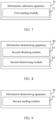
- FIG. 2 is a flowchart of an information indication method according to an embodiment of this application. The method is applied to a network device. As shown in FIG. 2 , the method includes the following steps.
- Step 201 Send control signaling to a terminal.
- control signaling is UL DCI or higher layer signaling.
- the control signaling includes at least one of a first parameter field and a DAI field, and the control signaling is used to indicate related information of SL feedback information.
- the first parameter field is used to indicate related information of SL feedback information
- the DAI field is used to indicate related information of SL feedback information or related information of Uu feedback information.
- the control signaling is sent to the terminal, where the control signaling is used to indicate related information of SL feedback information, and the related information of SL feedback information can help the terminal and the network device, for example, a base station, keep consistent understanding on the SL feedback information (for example, an SL codebook), thereby enhancing reliability of the SL feedback information.
- the control signaling is used to indicate related information of SL feedback information
- the related information of SL feedback information can help the terminal and the network device, for example, a base station, keep consistent understanding on the SL feedback information (for example, an SL codebook), thereby enhancing reliability of the SL feedback information.
- the higher layer signaling may include at least one of the following: RRC signaling, SIB, MAC layer signaling, RLC layer signaling, PDCP layer signaling, and SDAP layer signaling.
- the related information of SL feedback information may include at least one of the following:
- the case of the DAI field indicating related information of SL feedback information includes at least one of the following:
- control signaling may further include type indication information, where the type indication information is used to indicate that the control signaling indicates related information of SL feedback information, or the type indication information is used to indicate that the control signaling indicates related information of Uu feedback information.
- control signaling indicates the grant for the SL feedback information or the count information, of the SL DCI, that has a first preset number of bits:
- control signaling indicates the count information, of the SL DCI, that has a second preset number of bits:
- the information indication method provided in this embodiment of this application is a network-side method corresponding to the method embodiment shown in FIG. 1 .
- the same technical effects can be achieved. Details are not described herein again.
- a time offset of a time domain resource used for determining SL feedback information usually includes a dynamic time offset and a semi-static time offset.
- the two types of time offsets are usually configured, preconfigured, indicated, or defined in a protocol separately by using different signaling.
- a time domain resource for example, a PUCCH or a PUSCH
- the number of bits or content of the SL feedback information is related to a time offset associated with the time domain resource.
- SL feedback information associated only with the dynamic time offset is different from the semi-static time offset
- SL feedback information associated only with the semi-static time offset is different in terms of the number of bits and/or content, that is, the number of bits of the SL feedback information may change with time, which increases complexity of blind detection by the base station.
- consistent understanding on the number of bits of the SL feedback information cannot be maintained between the base station and a user, which reduces reliability. To resolve the problem that the number of bits of the SL feedback information may change and be inconsistent, this application proposes the following method.
- FIG. 3 is a flowchart of an information determining method according to an embodiment of this application. The method is applied to a terminal. As shown in FIG. 3 , the method includes the following steps.
- Step 301 Obtain a dynamic time offset and a semi-static time offset that are used for determining a time domain resource in which SL feedback information is carried.
- time offset (time offset) information for example, time offset K1 information, used for determining the time domain resource in which the SL feedback information is carried includes the dynamic time offset (a dynamic time offset K1) and/or the semi-static time offset (a semi-static time offset K1) may be defined in a protocol, configured by a control node, preconfigured, or indicated by another terminal.
- the dynamic time offset means that after the dynamic time offset is obtained (in this process, one or more time offsets may be defined in a protocol, configured by a control node, preconfigured, or indicated by another terminal), one or more of the dynamic time offset may (but not necessarily) be subsequently indicated by using first control signaling (for example, SL DCI, SCI, or a MAC CE).
- first control signaling for example, SL DCI, SCI, or a MAC CE
- a possible time offset that is configured by a base station as indicated by SL DCI used for scheduling SL resources is a dynamic time offset, for example, sl-FeedbackToUL-ACK-DG.
- a time offset indicated in DCI used to activate an SL CG type2 is a time offset of the SL CG type2 activated by the DCI.
- the DCI indicates a value of sl-FeedbackToUL-ACK-DG configured by the base station or a value index.
- the semi-static time offset is a time offset corresponding to a semi-static resource configuration.
- the semi-static resource may be an SL CG (sidelink configured grant, sidelink configured grant) configured by the base station, or another SL semi-static resource, for example, a semi-static resource recommended, scheduled, notified, or indicated by one or more SL UEs to one or more other SL UEs, or for example, a preconfigured semi-static SL resource.
- a time offset in an SL CG configuration is the sl-FeedbackToLTL-ACK-CG.
- a sidelink configured grant type1 (SL CG type1, sidelink configured grant type1) configuration includes a time offset of the SL CG type2, for example, the sl-FeedbackToLTL-ACK-CG.
- a sidelink configured grant type2 (SL CG type2, sidelink configured grant type2) configuration includes a time offset of the SL CG type2, for example, sl-FeedbackToUL-ACK-CG.
- a control node may configure one or more CGs (configured grant, configured grant), and each CG may have its own time offset.
- the control node may configure one or more CGs type1 (grant-free CG), and each CG type1 has its own time offset.
- the control node may configure one or more CGs type2 (grant-based CG), and DCI for activating a CG type2 has a time offset that includes at least one CG type2.
- Step 302 Determine any one of the following: the semi-static time offset includes the dynamic time offset, or the dynamic time offset includes the semi-static time offset.
- the semi-static time offset includes the dynamic time offset may be referred to as that the dynamic time offset belongs to the semi-static time offset, which may be understood as that a value range of the dynamic time offset is within a value range of the semi-static time offset.
- the dynamic time offset belongs to the semi-static time offset, which may be understood as that a value range of the dynamic time offset is within a value range of the semi-static time offset.
- values of the dynamic time offsets should all be one or more values within ⁇ 1, 2, 3 ⁇ .
- the dynamic time offset includes the semi-static time offset may be referred to as that the semi-static time offset belongs to the dynamic time offset, which may be understood as that a value range of the semi-static time offset is within a value range of the dynamic time offset.
- the semi-static time offset belongs to the dynamic time offset, which may be understood as that a value range of the semi-static time offset is within a value range of the dynamic time offset.
- values of the semi-static time offsets should all be one or more values within ⁇ 1, 2, 3 ⁇ .
- the dynamic time offset includes a plurality of values
- the semi-static time offset belongs to the dynamic time offset.
- the sl-FeedbackToLTL-ACK-DG includes a plurality of values
- the sl-FeedbackToLTL-ACK-CG belongs to the sl-FeedbackToLTL-ACK-DG.
- sl-FeedbackToUL-ACK-DG ⁇ 1, 2, 3 ⁇
- two SL CGs type1 are configured, which are SL CG type1#1 and SL CG type1#2
- a semi-static sl-FeedbackToUL-ACK-CG corresponding to the two SL CGs type1 should be a value within ⁇ 1, 2, 3 ⁇ .
- the sl-FeedbackToLTL-ACK-CG is equal to the sl-FeedbackToUL-ACK-DG.
- sl-FeedbackToUL-ACK-DG ⁇ 1 ⁇ and two SL CGs type1 are configured, which are SL CG type1#1 and SL CG type1#2, a semi-static sl-FeedbackToLTL-ACK-CG corresponding to the two SL CGs type1 should be 1.
- the semi-static time offset belongs to the dynamic time offset only when a preset condition 1 is met; otherwise (for example, when there is no dynamic scheduling, or no SL CG is configured, or no SL CG type1 is configured, or a type of the SL feedback information is a dynamic codebook or a type2 codebook), the semi-static time offset does not need to belong to the dynamic time offset.
- the preset condition 1 is that at least one of the following conditions is met.
- an SL CG (type1 and/or type2) is configured for the terminal, and/or monitoring SL DCI is configured for the terminal, and the type of the SL feedback information is semi-static.
- the semi-static time offset belongs to the dynamic time offset.
- an SL CG type 1 is configured for the terminal, and the following is met:
- An SL CG type2 is configured for the terminal, and/or the terminal needs to monitor or receive a DCI format 3_0.
- a group of time offsets K_1 is provided for the terminal, and the group of K_1 includes K_1 corresponding to the semi-static time offset and K_1 corresponding to the dynamic time offset.
- the semi-static time offset belongs to the dynamic time offset, in other words, a value corresponding to the dynamic time offset should include a value corresponding to the semi-static time offset.
- the requirement that the semi-static time offset belongs to the dynamic time offset does not need to be met. That is, the semi-static time offset and the dynamic time offset may be the same or different.
- the semi-static time offset used for determining the time domain resource in which the SL feedback information is carried belongs to the dynamic time offset, so that a size of the SL feedback information can be kept at a constant value or within a relatively stable range (especially when the SL feedback information is semi-static), thereby reducing complexity of blind detection by the base station and improving reliability.
- FIG. 4 is a flowchart of an information configuration method according to an embodiment of this application. The method is applied to a network device. As shown in FIG. 4 , the method includes the following steps.
- Step 401 Send configuration information to a terminal.
- the configuration information indicates a dynamic time offset and a semi-static time offset that are used for determining a time domain resource in which SL feedback information is carried; and the semi-static time offset includes the dynamic time offset, or the dynamic time offset includes the semi-static time offset.
- the dynamic time offset and the semi-static time offset refer to the descriptions in the embodiment shown in FIG. 3 . Details are not described herein again.
- the configuration information may include first configuration information and second configuration information, where the first configuration information is used to indicate the dynamic time offset, and the second configuration information is used to indicate the semi-static time offset.
- the first configuration information and the second configuration information may be sent simultaneously, or may not be sent simultaneously, for example, the first configuration information is sent before the second configuration information is sent, or the second configuration information is sent before the first configuration information is sent.
- the dynamic time offset includes the semi-static time offset, or the semi-static time offset includes the dynamic time offset.
- the information determining method provided in this embodiment of this application is a network-side method corresponding to the method embodiment shown in FIG. 3 .
- the same technical effects can be achieved. Details are not described herein again.
- a time domain position corresponding to a time offset used for determining a time domain resource in which SL feedback information is carried that is, a time domain position of a resource associated with a resource for transmitting the SL feedback information
- a time domain position of a resource associated with a resource for transmitting the SL feedback information belongs to a plurality of resource pools
- this application proposes the following method.
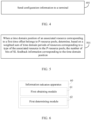
- FIG. 5 is a flowchart of an information determining method according to an embodiment of this application.
- the method is applied to a communication device.
- the communication device is a terminal or a network device.
- the method includes the following steps.
- Step 501 When a time domain position of an associated resource corresponding to a first time offset belongs to P resource pools, determine, based on a weighted sum of time domain periods of a first resource, the number of bits of SL feedback information corresponding to the time domain position.
- a time domain period may also be interpreted as a time domain density.
- the time domain period is N slots, that is, there is an associated resource for every N slots.
- P is a positive integer greater than 1
- the first time offset is a time offset used for determining a time domain resource in which the SL feedback information is carried.
- the associated resource is a resource associated with a resource for transmitting the SL feedback information.
- the first resource is a resource corresponding to a type of the associated resource in the P resource pools.
- the number of bits of the SL feedback information is determined in the foregoing manner, which can help a user and a base station achieve consistent understanding on the SL feedback information when there are a plurality of resource pools, thereby avoiding missing some SL feedback information and enhancing reliability.
- time offset information used for determining the time domain resource in which the SL feedback information is carried may be defined in a protocol, configured by a control node, preconfigured, or indicated by another terminal.
- An associated resource associated with the SL feedback information (in other words, an associated resource associated with a resource in which the SL feedback information is carried) may be determined based on the time offset information.
- the associated resource includes a time domain resource and/or a frequency domain resource.
- a type of the associated resource may be a PSFCH.
- an associated PSFCH reception occasion (reception occasion) is determined.
- the P resource pools are resource pools on a same SL BWP or different SL BWPs.
- the P resource pools are resource pools on an active SL BWP or a configured SL BWP, or resource pools on a preconfigured SL BWP.
- the P resource pools are SL resource pools on a same carrier or different carriers.
- a reference point plus the time domain resource corresponding to the time offset is equal to the time domain resource for transmitting the SL feedback information. Therefore, it can be learned through backward deduction that the resource in which the SL feedback information is carried minus the time domain resource corresponding to the time offset is related to the SL feedback information.
- a time domain position of an associated resource corresponding to a time offset belongs to P resource pools and is denoted as ⁇ pool_0, pool_1, pool_2, ..., pool_p, ..., pool_(P - 1) ⁇
- T is a sum of time domain periods or time domain densities of PSFCH resources in all of the P resource pools.
- the P resource pools may be resource pools that include resources corresponding to the type of the associated resource.
- the P resource pools are resource pools that include a slot in which the PSFCH is carried and that include PSFCHs but may or may not include PSFCHs in the slot.
- the P resource pools are resource pools that include the slot 1 and that include PSFCHs.
- some resource pools may have a PSFCH in the slot 1, and some may have a PSFCH in a slot other than the slot 1.
- the P resource pools may be resource pools that include resources corresponding to the type of the associated resource and that include resources corresponding to the type of the associated resource at the time domain position of the associated resource.
- the type of the associated resource is a PSFCH
- the P resource pools are resource pools that include a slot in which the PSFCH is carried and that include PSFCHs in the slot.
- the P resource pools are resource pools that include the slot 1 and that include PSFCHs in the slot 1.
- N p corresponding to the one or more resource pools may be any of the following:
- Embodiment 1 An SL parameter field is introduced into UL DCI to indicate a SAI.
- the UL DCI includes the SAI:
- the UL DCI includes the SAI:
- the UL DCI includes a DAI and the SAI:
- the LTL DCI may be in a DCI format 0-1.
- Embodiment 2 An existing field (for example, a DAI field) in UL DCI is used to indicate a SAI, and some fields are reused.
- a DAI field for example, a DAI field
- the UL DCI may indicate a grant for SL feedback information by using a first DAI field.
- the UL DCI includes:
- the UL DCI indicates a SAI by using a DAI field.
- the UL DCI includes:
- the LTL DCI may be in a DCI format 0-1.
- Embodiment 3 A type1 codebook (a semi-static codebook) is determined based on a SAI in DCI.
- a user wants to transmit SL feedback information in a PUSCH not scheduled by DCI (for example, a PUSCH on a LTL configured grant) or in a PUSCH scheduled by a DCI format 0_0, for example, reusing SL HARQ-ACK information in the PUSCH for transmission:
- SL DCI later than the foregoing LTL DCI (a DCI format 0_0 or a DCI format 0_1)
- a bit corresponding to the SL DCI in the SL feedback information is set to a NACK.
- the user does not want to receive, in the first N2' symbols of the PUSCH, DCI for downlink BWP switching or uplink BWP switching, where N2' is a processing delay.
- N2' is a processing delay.
- N2' is related to at least one of the number of PSFCHs received by the user, a capability of a PSFCH received by the user, the number of bits included in the SL feedback information, an SL SCS (subcarrier spacing, subcarrier spacing), and a PUSCH SCS.
- the SL feedback information can be reused in the PUSCH.
- an implementation is replacing V T ⁇ SAI UL with V C ⁇ SAI SL .
- Embodiment 4 A type2 codebook (a dynamic codebook) is determined based on a SAI in DCI.
- a user wants to transmit SL feedback information in a PUSCH not scheduled by DCI (for example, a PUSCH on a LTL configured grant) or in a PUSCH scheduled by a DCI format 0_0, for example, reusing SL HARQ-ACK information in the PUSCH for transmission:
- the user wants to transmit SL feedback information in a PUSCH scheduled by a DCI format 0_1, for example, reusing SL HARQ-ACK information in the PUSCH for transmission, the user generates SL feedback information.
- the generation process :
- the user does not have SL feedback information corresponding to SL DCI (for example, the user does not receive SL DCI associated with a PSFCH) or SL feedback information corresponding to an SL CG (for example, the user does not have SL feedback information corresponding to a PSFCH associated with an SL CG), the user does not reuse SL HARQ-ACK information in the PUSCH.
- V T ⁇ S AI UL in the foregoing example is replaced with V C ⁇ S AI SL .
- Embodiment 5 A semi-static time offset K1 belongs to a dynamic time offset K1.
- At least one SL configured grant type1 is configured for user equipment and at least one of the following is met:
- Embodiment 6 The number of bits of SL feedback information is determined.
- a slot determined based on a time offset K1 belongs to P sidelink resource pools and includes a PSFCH resource
- a PSFCH period periodPSFCHresource of a resource pool pool_p in the P resource pools is denoted as N PSFCH_p
- a slot determined based on a time offset K1 belongs to P sidelink resource pools and includes a PSFCH resource
- the P resource pools are denoted as ⁇ pool_0, pool_1, pool_2, ..., pool_p, ..., pool_(P - 1) ⁇
- a PSFCH period periodPSFCHresource of a resource pool pool_p in the P resource pools is denoted as N PSFCH_p
- corresponding SL feedback information may be determined by using the following method:
- An interpretation of M A is a PSSCH transmission occasion associated with a resource in which SL feedback information is carried, and j is used to indicate the number of bits of the SL feedback information.
- the information indication method provided in the embodiments of this application may be performed by an information indication apparatus, or by a control module in such information indication apparatus for performing or loading the information indication method.
- an information indication apparatus performing or loading the information indication method is used as an example for describing the information indication method provided in the embodiments of this application.
- FIG. 6 is a schematic structural diagram of an information indication apparatus according to an embodiment of this application.
- the apparatus is applied to a terminal.
- the information indication apparatus 60 includes:
- the related information of SL feedback information includes at least one of the following:
- the case of the DAI field indicating related information of SL feedback information includes at least one of the following:
- control signaling further includes type indication information, where the type indication information is used to indicate that the control signaling indicates related information of SL feedback information, or the type indication information is used to indicate that the control signaling indicates related information of Uu feedback information.
- control signaling indicates the grant for the SL feedback information and/or the count information, of the SL DCI, that has a first preset number of bits:
- control signaling indicates a SAI, of the SL DCI, that has a second preset number of bits:
- the information indication apparatus 60 may further include: a transmitting module, configured to: in a case that an uplink resource scheduled by the UL DCI collides with a resource of the SL feedback information, use the uplink resource for transmission of SL feedback information.
- a transmitting module configured to: in a case that an uplink resource scheduled by the UL DCI collides with a resource of the SL feedback information, use the uplink resource for transmission of SL feedback information.
- the information indication apparatus 60 provided in this embodiment of this application is capable of implementing the processes implemented in the method embodiment shown in FIG. 1 , with the same technical effects achieved. To avoid repetition, details are not described herein again.
- FIG. 7 is a schematic structural diagram of an information indication apparatus according to an embodiment of this application.
- the apparatus is applied to a network device.
- the information indication apparatus 70 includes:
- the related information of SL feedback information includes at least one of the following:
- the case of the DAI field indicating related information of SL feedback information includes at least one of the following:
- control signaling further includes type indication information, where the type indication information is used to indicate that the control signaling indicates related information of SL feedback information, or the type indication information is used to indicate that the control signaling indicates related information of Uu feedback information.
- control signaling indicates the grant for the SL feedback information and/or the count information, of the SL DCI, that has a first preset number of bits:
- control signaling indicates a SAI, of the SL DCI, that has a second preset number of bits:
- the information indication apparatus 70 provided in this embodiment of this application is capable of implementing the processes implemented in the method embodiment shown in FIG. 2 , with the same technical effects achieved. To avoid repetition, details are not described herein again.
- the information determining method provided in the embodiments of this application may be performed by an information determining apparatus, or by a control module in such information determining apparatus for performing or loading the information determining method.
- an information determining apparatus performing or loading the information determining method is used as an example for describing the information determining method provided in the embodiments of this application.
- FIG. 8 is a schematic structural diagram of an information determining apparatus according to an embodiment of this application.
- the apparatus is applied to a terminal.
- the information determining apparatus 80 includes:
- the information determining apparatus 80 provided in this embodiment of this application is capable of implementing the processes implemented in the method embodiment shown in FIG. 3 , with the same technical effects achieved. To avoid repetition, details are not described herein again.
- FIG. 9 is a schematic structural diagram of an information determining apparatus according to an embodiment of this application.
- the apparatus is applied to a network device.
- the information determining apparatus 90 includes:
- the dynamic time offset includes the semi-static time offset, or the dynamic time offset includes the dynamic time offset.
- FIG. 10 is a schematic structural diagram of an information determining apparatus according to an embodiment of this application.
- the apparatus is applied to a communication device.
- the communication device is a terminal or a network device.
- the information determining apparatus 10 includes:
- the information determining apparatus 10 provided in this embodiment of this application is capable of implementing the processes implemented in the method embodiment shown in FIG. 5 , with the same technical effects achieved. To avoid repetition, details are not described herein again.
- the information indication apparatus or the information determining apparatus in the embodiments of this application may be an apparatus, or may be a component, an integrated circuit, or a chip in a terminal.
- the apparatus may be a mobile electronic device or a non-mobile electronic device.
- the mobile electronic device may be a mobile phone, a tablet computer, a notebook computer, a palmtop computer, a vehicle-mounted electronic device, a wearable device, an ultra-mobile personal computer (ultra-mobile personal computer, UMPC), a netbook, or a personal digital assistant (personal digital assistant, PDA), and the non-mobile electronic device may be a server, a network attached storage (Network Attached Storage, NAS), a personal computer (personal computer, PC), a television (television, TV), a teller machine, or a self-service machine. This is not specifically limited in the embodiments of this application.
- the information indication apparatus or the information determining apparatus in the embodiments of this application may be an apparatus with an operating system.
- the operating system may be an Android (Android) operating system, may be an iOS operating system, or may be another possible operating system. This is not specifically limited in the embodiments of this application.
- An embodiment of this application further provides a communication device, including a processor, a memory, and a program or instructions stored in the memory and capable of running on the processor.
- a communication device including a processor, a memory, and a program or instructions stored in the memory and capable of running on the processor.
- the program or instructions are executed by the processor, the processes of the method embodiment shown in any one of FIG. 1 to FIG. 5 may be implemented, with the same technical effects achieved. To avoid repetition, details are not described herein again.
- the communication device may be a terminal or a network device.
- FIG. 11 is a schematic diagram of a hardware structure of a terminal for implementing the embodiments of the present invention.
- the terminal 1100 includes but is not limited to components such as a radio frequency unit 1101, a network module 1102, an audio output unit 1103, an input unit 1104, a sensor 1105, a display unit 1106, a user input unit 1107, an interface unit 1108, a memory 1109, and a processor 1110.
- the terminal 1100 may further include a power supply (for example, a battery) that supplies power to the components.
- the power supply may be logically connected to the processor 1110 through a power management system. In this way, functions such as charge management, discharge management, and power consumption management are implemented by using the power management system.
- the structure of the terminal shown in FIG. 11 does not constitute any limitation on the terminal.
- the terminal may include more or fewer components than shown in the figure, or a combination of some components, or the components disposed differently. Details are not described herein again.
- the processor 1110 may be configured to: obtain control signaling, where the control signaling is UL DCI or higher layer signaling; and determine related information of SL feedback information based on the control signaling, where the control signaling includes at least one of a first parameter field and a DAI field, the first parameter field is used to indicate related information of SL feedback information, and the DAI field is used to indicate related information of SL feedback information or related information of Uu feedback information.
- the processor 1110 may be configured to: obtain a dynamic time offset and a semi-static time offset that are used for determining a time domain resource in which SL feedback information is carried; and in a case that the dynamic time offset includes one or more time offsets, determine any one of the following: the semi-static time offset includes the dynamic time offset, or the dynamic time offset includes the semi-static time offset.
- the processor 1110 may be configured to: when a time domain position of an associated resource corresponding to a first time offset belongs to P resource pools, determine, based on a weighted sum of time domain periods of a first resource, the number of bits of SL feedback information corresponding to the time domain position, where P is a positive integer greater than 1, the first time offset is a time offset used for determining a time domain resource in which the SL feedback information is carried, the associated resource is a resource associated with a resource for transmitting the SL feedback information, and the first resource is a resource corresponding to a type of the associated resource in the P resource pools.
- terminal 1100 in this embodiment of this application is capable of implementing the processes implemented in the method embodiment shown in FIG. 1, FIG. 3 , or FIG. 5 , with the same beneficial effects achieved. To avoid repetition, details are not described herein again.
- FIG. 12 is a schematic diagram of a hardware structure of a network device for implementing the embodiments of the present invention.
- the network device 120 includes but is not limited to a bus 121, a transceiver 122, an antenna 123, a bus interface 124, a processor 125, and a memory 126.
- the network device 120 further includes a program or instructions stored in the memory 126 and capable of running on the processor 125.
- control signaling when the program or instructions are executed by the processor 125, the following step is implemented: sending control signaling to a terminal, where the control signaling includes at least one of a first parameter field and a DAI field, the control signaling is used to indicate related information of SL feedback information, the first parameter field is used to indicate related information of SL feedback information, the DAI field is used to indicate related information of SL feedback information or related information of Uu feedback information, and the control signaling is UL DCI or higher layer signaling.
- the following step is implemented: sending configuration information to a terminal, where the configuration information indicates a dynamic time offset and a semi-static time offset that are used for determining a time domain resource in which SL feedback information is carried; and the semi-static time offset includes the dynamic time offset, or the dynamic time offset includes the semi-static time offset.
- the following step is implemented: when a time domain position of an associated resource corresponding to a first time offset belongs to P resource pools, determining, based on a weighted sum of time domain periods of a first resource, the number of bits of SL feedback information corresponding to the time domain position, where P is a positive integer greater than 1, the first time offset is a time offset used for determining a time domain resource in which the SL feedback information is carried, the associated resource is a resource associated with a resource for transmitting the SL feedback information, and the first resource is a resource corresponding to a type of the associated resource in the P resource pools.
- the network device 120 in this embodiment of this application is capable of implementing the processes implemented in the method embodiment shown in FIG. 2 , FIG. 4, or FIG. 5 , with the same beneficial effects achieved. To avoid repetition, details are not described herein again.
- the transceiver 122 is configured to receive and send data under control of the processor 125.
- a bus architecture (represented by the bus 121), that is, the bus 121, may include any quantity of interconnected buses and bridges, and the bus 121 connects various circuits of one or more processors represented by the processor 125 and a memory represented by the memory 126.
- the bus 121 may further connect various other circuits such as a peripheral device, a voltage regulator, and a power management circuit. These are all well-known in the art, and therefore are not further described in this specification.
- the bus interface 124 provides an interface between the bus 121 and the transceiver 122.
- the transceiver 122 may be one element, or may be a plurality of elements, for example, a plurality of receivers and transmitters, and provides a unit for communicating with various other apparatuses on a transmission medium.
- Data processed by the processor 125 is transmitted on a wireless medium through the antenna 123. Further, the antenna 123 also receives data and transmits the data to the processor 125.
- the processor 125 is responsible for managing the bus 121 and general processing, and may further provide various functions, including timing, a peripheral interface, voltage regulation, power management, and other control functions.
- the memory 126 may be configured to store data that is used by the processor 125 when the processor 125 performs an operation.
- the processor 125 may be a CPU, an ASIC, an FPGA, or a CPLD.
- An embodiment of this application further provides a readable storage medium, where the readable storage medium stores a program or instructions, and when the program or instructions are executed by a processor, the processes of the method embodiment shown in any one of FIG. 1 to FIG. 5 may be implemented, with the same technical effects achieved. To avoid repetition, details are not described herein again.
- the processor is a processor in the network device in the foregoing embodiments.
- the readable storage medium includes a computer-readable storage medium, for example, a computer read-only memory (Read-Only Memory, ROM), a random access memory (Random Access Memory, RAM), a magnetic disk, or an optical disc.
- An embodiment of this application further provides a chip, where the chip includes a processor and a communication interface, the communication interface is coupled to the processor, and the processor is configured to run a program or instructions, so as to implement the processes of the method embodiment shown in any one of FIG. 1 to FIG. 5 , with the same technical effects achieved. To avoid repetition, details are not described herein again.
- the chip mentioned in this embodiment of this application may also be referred to as a system-level chip, a system chip, a chip system, a system-on-a-chip, or the like.
- the computer software product is stored in a storage medium (for example, a ROM/RAM, a magnetic disk, or a compact disc), and includes several instructions for instructing a terminal (which may be a mobile phone, a computer, a server, an air conditioner, a network device, or the like) to perform the methods described in the embodiments of this application.
- a storage medium for example, a ROM/RAM, a magnetic disk, or a compact disc
- a terminal which may be a mobile phone, a computer, a server, an air conditioner, a network device, or the like
Landscapes
- Engineering & Computer Science (AREA)
- Signal Processing (AREA)
- Computer Networks & Wireless Communication (AREA)
- Quality & Reliability (AREA)
- Mobile Radio Communication Systems (AREA)
Applications Claiming Priority (2)
| Application Number | Priority Date | Filing Date | Title |
|---|---|---|---|
| CN202010414536.3A CN113676302B (zh) | 2020-05-15 | 2020-05-15 | 信息指示、信息确定方法、装置和通信设备 |
| PCT/CN2021/093019 WO2021228079A1 (zh) | 2020-05-15 | 2021-05-11 | 信息指示、信息确定方法、装置和通信设备 |
Publications (2)
| Publication Number | Publication Date |
|---|---|
| EP4138328A1 true EP4138328A1 (de) | 2023-02-22 |
| EP4138328A4 EP4138328A4 (de) | 2023-10-11 |
Family
ID=78525988
Family Applications (1)
| Application Number | Title | Priority Date | Filing Date |
|---|---|---|---|
| EP21803073.2A Pending EP4138328A4 (de) | 2020-05-15 | 2021-05-11 | Informationsanzeigeverfahren und -vorrichtung, informationsbestimmungsverfahren und -vorrichtung und kommunikationsvorrichtung |
Country Status (6)
| Country | Link |
|---|---|
| US (2) | US20230077372A1 (de) |
| EP (1) | EP4138328A4 (de) |
| JP (2) | JP7434607B2 (de) |
| KR (2) | KR20230010042A (de) |
| CN (1) | CN113676302B (de) |
| WO (1) | WO2021228079A1 (de) |
Families Citing this family (4)
| Publication number | Priority date | Publication date | Assignee | Title |
|---|---|---|---|---|
| EP4057708B1 (de) * | 2021-01-14 | 2024-08-28 | Lg Electronics Inc. | Verfahren und vorrichtung zur durchführung eines priorisierungsverfahrens in nr v2x |
| WO2023108386A1 (en) * | 2021-12-14 | 2023-06-22 | Qualcomm Incorporated | Joint type-2 hybrid automatic repeat request codebook for downlink and sidelink communications |
| CN117375783A (zh) * | 2022-07-01 | 2024-01-09 | 上海朗帛通信技术有限公司 | 一种用于无线通信的方法和装置 |
| CN115766473B (zh) * | 2022-10-28 | 2024-04-12 | 南方电网数字平台科技(广东)有限公司 | 一种适用于云平台运营的资源容量规划的方法 |
Family Cites Families (25)
| Publication number | Priority date | Publication date | Assignee | Title |
|---|---|---|---|---|
| EP2835022B1 (de) * | 2012-04-05 | 2017-05-24 | Nokia Solutions and Networks Oy | Kommunikation zwischen vorrichtungen |
| EP3309986B1 (de) * | 2015-08-10 | 2020-07-29 | Huawei Technologies Co., Ltd. | Sende- und empfangsverfahren für rückmeldeinformationen sowie benutzergerät und zugangsnetzvorrichtung |
| CN108075864B (zh) * | 2016-11-15 | 2021-02-05 | 中国电信股份有限公司 | Ack/nack的反馈方法、系统以及终端 |
| CN108923894B (zh) * | 2017-03-23 | 2023-04-18 | 中兴通讯股份有限公司 | 一种信息传输的方法、用户设备、基站、存储介质和系统 |
| CN108810906A (zh) * | 2017-05-04 | 2018-11-13 | 株式会社Ntt都科摩 | 资源配置和调度方法、基站以及用户设备 |
| WO2019004881A1 (en) * | 2017-06-27 | 2019-01-03 | Telefonaktiebolaget Lm Ericsson (Publ) | FEEDBACK SIGNALING FORMAT SELECTION |
| CN109391422B (zh) * | 2017-08-11 | 2020-11-17 | 华为技术有限公司 | 一种反馈码本确定的方法及终端设备、网络设备 |
| WO2019031998A1 (en) * | 2017-08-11 | 2019-02-14 | Telefonaktiebolaget Lm Ericsson (Publ) | ORDER INFORMATION CODE RATE |
| WO2019036578A1 (en) * | 2017-08-17 | 2019-02-21 | Intel Corporation | Selecting resources for sidelink communication based on geo-location information |
| US10716127B2 (en) * | 2017-09-19 | 2020-07-14 | Mediatek Inc. | Uplink channel information feedback timing signaling in wireless communications |
| CN109639398B (zh) * | 2017-10-09 | 2021-12-31 | 华为技术有限公司 | Harq-ack反馈码本的发送方法、装置及设备 |
| CN110086583B (zh) * | 2018-01-26 | 2021-05-07 | 电信科学技术研究院有限公司 | 一种dai的指示方法、用户终端和网络侧设备 |
| CN110351016B (zh) * | 2018-04-04 | 2021-11-19 | 展讯通信(上海)有限公司 | 下行控制信息的传输方法及装置 |
| US11382083B2 (en) * | 2018-07-23 | 2022-07-05 | Samsung Electronics Co., Ltd. | Method and apparatus for high reliability transmission in vehicle to everything (V2X) communication |
| US20200037343A1 (en) * | 2018-07-24 | 2020-01-30 | Samsung Electronics Co., Ltd. | Method and apparatus for network controlled resource allocation in nr v2x |
| CN110830151B (zh) * | 2018-08-07 | 2021-06-15 | 华为技术有限公司 | 反馈信息的传输方法和装置 |
| WO2020067782A1 (en) * | 2018-09-28 | 2020-04-02 | Samsung Electronics Co., Ltd. | Method and device for transmitting or receiving groupcast feedback in wireless cellular communication system |
| US11109378B2 (en) * | 2018-11-01 | 2021-08-31 | Huawei Technologies Co., Ltd. | Methods and apparatus for sidelink communications configuration |
| CN111148077B (zh) * | 2018-11-02 | 2021-06-29 | 华为技术有限公司 | 传输方法和装置 |
| EP3890246B1 (de) * | 2018-11-29 | 2025-06-11 | Beijing Xiaomi Mobile Software Co., Ltd. | Verfahren und vorrichtung zur rückkopplung von csi-messungen und speichermedium |
| WO2020222575A1 (en) * | 2019-05-02 | 2020-11-05 | Samsung Electronics Co., Ltd. | Method and apparatus for transmission and reception of sidelink feedback in wireless communication system |
| CN118449661A (zh) * | 2019-08-16 | 2024-08-06 | 创新技术实验室株式会社 | 用于在无线通信中使用harq的方法和装置 |
| CN110519025B (zh) * | 2019-08-16 | 2021-12-10 | 中国信息通信研究院 | 一种半静态调度混合自动重传请求反馈方法和设备 |
| CN110740016B (zh) * | 2019-10-06 | 2022-09-09 | 中国信息通信研究院 | 一种车联网通信反馈定时方法和设备 |
| KR102931538B1 (ko) * | 2020-02-12 | 2026-02-27 | 엘지전자 주식회사 | Nr v2x에서 사이드링크 cg 자원을 기반으로 사이드링크 통신을 수행하는 방법 및 장치 |
-
2020
- 2020-05-15 CN CN202010414536.3A patent/CN113676302B/zh active Active
-
2021
- 2021-05-11 KR KR1020227043553A patent/KR20230010042A/ko active Pending
- 2021-05-11 KR KR1020267007778A patent/KR20260042606A/ko active Pending
- 2021-05-11 WO PCT/CN2021/093019 patent/WO2021228079A1/zh not_active Ceased
- 2021-05-11 JP JP2022568836A patent/JP7434607B2/ja active Active
- 2021-05-11 EP EP21803073.2A patent/EP4138328A4/de active Pending
-
2022
- 2022-11-13 US US17/985,874 patent/US20230077372A1/en active Pending
-
2024
- 2024-02-07 JP JP2024017123A patent/JP7618860B2/ja active Active
-
2025
- 2025-09-18 US US19/332,238 patent/US20260020034A1/en active Pending
Also Published As
| Publication number | Publication date |
|---|---|
| KR20230010042A (ko) | 2023-01-17 |
| US20230077372A1 (en) | 2023-03-16 |
| EP4138328A4 (de) | 2023-10-11 |
| KR20260042606A (ko) | 2026-03-31 |
| JP7434607B2 (ja) | 2024-02-20 |
| JP7618860B2 (ja) | 2025-01-21 |
| WO2021228079A1 (zh) | 2021-11-18 |
| CN113676302A (zh) | 2021-11-19 |
| US20260020034A1 (en) | 2026-01-15 |
| CN113676302B (zh) | 2023-02-21 |
| JP2023525551A (ja) | 2023-06-16 |
| JP2024050840A (ja) | 2024-04-10 |
Similar Documents
| Publication | Publication Date | Title |
|---|---|---|
| US20230077372A1 (en) | Information indication method and apparatus, information determining method and apparatus, and communication device | |
| US20250317936A1 (en) | Method and apparatus for transmitting information on an uplink channel | |
| US11229042B2 (en) | Method and apparatus for determining and communicating multi-stage sidelink control information | |
| US11595991B2 (en) | Method for indicating the allocated resources for a HARQ message in a random access procedure for a low-complexity, narrowband terminal | |
| US12003328B2 (en) | Method and apparatus for HARQ-ACK codebook reduction | |
| EP2862400B1 (de) | Vorrichtungen zum senden und empfangen von feedback-informationen | |
| EP3800817B1 (de) | Verfahren und vorrichtung zur erzeugung von informationen über hybride automatische wiederholungsanfragen (harq) | |
| US9451610B2 (en) | Wireless terminal and base station | |
| US20230163899A1 (en) | Harq processing method, user equipment, and base station | |
| EP4325762A1 (de) | Verfahren zur bestimmung von sidelink-feedbackressourcen, endgerät und netzwerkseitige vorrichtung | |
| EP3497842B1 (de) | Kommunikationssystem | |
| EP2840863B1 (de) | Interferenzreduzierung zwischen benachbarten drahtlosen Technologien | |
| CN111884770B (zh) | Harq-ack码本产生方法 | |
| EP3697044A1 (de) | Funknetzwerkknoten, drahtlose vorrichtung und darin ausgeführte verfahren | |
| CN116455529B (zh) | 混合自动重传请求应答harq-ack的反馈方法和终端设备 | |
| US12425169B2 (en) | Method and apparatus for transmitting and receiving sidelink feedback information | |
| US20250055648A1 (en) | Information feedback method and apparatuses thereof | |
| US20180242117A1 (en) | Enhancing Group Communication Services | |
| US20260067887A1 (en) | Transmission information determining method, configuration information sending method, terminal, and device | |
| EP3032901B1 (de) | Informationsübertragungsverfahren und -vorrichtung | |
| EP4645729A2 (de) | Vorrichtung und verfahren zur herstellung einer sidelink-kommunikation über einen unlizenzierten träger | |
| CN118524548A (zh) | 副链路sl传输方法、装置及第一终端 |
Legal Events
| Date | Code | Title | Description |
|---|---|---|---|
| STAA | Information on the status of an ep patent application or granted ep patent |
Free format text: STATUS: THE INTERNATIONAL PUBLICATION HAS BEEN MADE |
|
| PUAI | Public reference made under article 153(3) epc to a published international application that has entered the european phase |
Free format text: ORIGINAL CODE: 0009012 |
|
| STAA | Information on the status of an ep patent application or granted ep patent |
Free format text: STATUS: REQUEST FOR EXAMINATION WAS MADE |
|
| 17P | Request for examination filed |
Effective date: 20221116 |
|
| AK | Designated contracting states |
Kind code of ref document: A1 Designated state(s): AL AT BE BG CH CY CZ DE DK EE ES FI FR GB GR HR HU IE IS IT LI LT LU LV MC MK MT NL NO PL PT RO RS SE SI SK SM TR |
|
| DAV | Request for validation of the european patent (deleted) | ||
| DAX | Request for extension of the european patent (deleted) | ||
| A4 | Supplementary search report drawn up and despatched |
Effective date: 20230908 |
|
| RIC1 | Information provided on ipc code assigned before grant |
Ipc: H04W 72/12 20230101ALI20230904BHEP Ipc: H04L 5/00 20060101AFI20230904BHEP |
|
| STAA | Information on the status of an ep patent application or granted ep patent |
Free format text: STATUS: EXAMINATION IS IN PROGRESS |
|
| 17Q | First examination report despatched |
Effective date: 20241212 |