EP4138527B1 - Endgerätevorrichtung - Google Patents
Endgerätevorrichtung Download PDFInfo
- Publication number
- EP4138527B1 EP4138527B1 EP22789821.0A EP22789821A EP4138527B1 EP 4138527 B1 EP4138527 B1 EP 4138527B1 EP 22789821 A EP22789821 A EP 22789821A EP 4138527 B1 EP4138527 B1 EP 4138527B1
- Authority
- EP
- European Patent Office
- Prior art keywords
- main body
- opening
- terminal device
- disposed
- isolation groove
- Prior art date
- Legal status (The legal status is an assumption and is not a legal conclusion. Google has not performed a legal analysis and makes no representation as to the accuracy of the status listed.)
- Active
Links
Images




Classifications
-
- G—PHYSICS
- G06—COMPUTING OR CALCULATING; COUNTING
- G06F—ELECTRIC DIGITAL DATA PROCESSING
- G06F1/00—Details not covered by groups G06F3/00 - G06F13/00 and G06F21/00
- G06F1/16—Constructional details or arrangements
- G06F1/1613—Constructional details or arrangements for portable computers
- G06F1/1626—Constructional details or arrangements for portable computers with a single-body enclosure integrating a flat display, e.g. Personal Digital Assistants [PDAs]
-
- H—ELECTRICITY
- H04—ELECTRIC COMMUNICATION TECHNIQUE
- H04M—TELEPHONIC COMMUNICATION
- H04M1/00—Substation equipment, e.g. for use by subscribers
- H04M1/02—Constructional features of telephone sets
- H04M1/0202—Portable telephone sets, e.g. cordless phones, mobile phones or bar type handsets
- H04M1/026—Details of the structure or mounting of specific components
- H04M1/0277—Details of the structure or mounting of specific components for a printed circuit board assembly
-
- G—PHYSICS
- G06—COMPUTING OR CALCULATING; COUNTING
- G06F—ELECTRIC DIGITAL DATA PROCESSING
- G06F1/00—Details not covered by groups G06F3/00 - G06F13/00 and G06F21/00
- G06F1/16—Constructional details or arrangements
- G06F1/1613—Constructional details or arrangements for portable computers
- G06F1/1633—Constructional details or arrangements of portable computers not specific to the type of enclosures covered by groups G06F1/1615 - G06F1/1626
- G06F1/1656—Details related to functional adaptations of the enclosure, e.g. to provide protection against EMI, shock, water, or to host detachable peripherals like a mouse or removable expansions units like PCMCIA cards, or to provide access to internal components for maintenance or to removable storage supports like CDs or DVDs, or to mechanically mount accessories
-
- G—PHYSICS
- G06—COMPUTING OR CALCULATING; COUNTING
- G06F—ELECTRIC DIGITAL DATA PROCESSING
- G06F1/00—Details not covered by groups G06F3/00 - G06F13/00 and G06F21/00
- G06F1/16—Constructional details or arrangements
- G06F1/1613—Constructional details or arrangements for portable computers
- G06F1/1633—Constructional details or arrangements of portable computers not specific to the type of enclosures covered by groups G06F1/1615 - G06F1/1626
- G06F1/1684—Constructional details or arrangements related to integrated I/O peripherals not covered by groups G06F1/1635 - G06F1/1675
-
- H—ELECTRICITY
- H04—ELECTRIC COMMUNICATION TECHNIQUE
- H04M—TELEPHONIC COMMUNICATION
- H04M1/00—Substation equipment, e.g. for use by subscribers
- H04M1/02—Constructional features of telephone sets
- H04M1/0202—Portable telephone sets, e.g. cordless phones, mobile phones or bar type handsets
- H04M1/026—Details of the structure or mounting of specific components
- H04M1/0274—Details of the structure or mounting of specific components for an electrical connector module
-
- H—ELECTRICITY
- H04—ELECTRIC COMMUNICATION TECHNIQUE
- H04M—TELEPHONIC COMMUNICATION
- H04M1/00—Substation equipment, e.g. for use by subscribers
- H04M1/02—Constructional features of telephone sets
- H04M1/18—Telephone sets specially adapted for use in ships, mines, or other places exposed to adverse environment
-
- H—ELECTRICITY
- H05—ELECTRIC TECHNIQUES NOT OTHERWISE PROVIDED FOR
- H05K—PRINTED CIRCUITS; CASINGS OR CONSTRUCTIONAL DETAILS OF ELECTRIC APPARATUS; MANUFACTURE OF ASSEMBLAGES OF ELECTRICAL COMPONENTS
- H05K5/00—Casings, cabinets or drawers for electric apparatus
- H05K5/02—Details
- H05K5/0247—Electrical details of casings, e.g. terminals, passages for cables or wiring
-
- H—ELECTRICITY
- H05—ELECTRIC TECHNIQUES NOT OTHERWISE PROVIDED FOR
- H05K—PRINTED CIRCUITS; CASINGS OR CONSTRUCTIONAL DETAILS OF ELECTRIC APPARATUS; MANUFACTURE OF ASSEMBLAGES OF ELECTRICAL COMPONENTS
- H05K5/00—Casings, cabinets or drawers for electric apparatus
- H05K5/06—Hermetically-sealed casings
- H05K5/069—Other details of the casing, e.g. wall structure, passage for a connector, a cable, a shaft
Definitions
- This application relates to the field of communication device technologies, and in particular, to a terminal device.
- a waterproof and sealing level of a terminal that is positioned as a high-end product even needs to reach at least an IPX7 level.
- a waterproof and sealing design that can reach at least the IPX7 level is usually implemented by improving waterproof and sealing performance of components such as an interface component exposed to a housing of a terminal. This also leads to high waterproof and sealing costs of the terminal, and is not conducive to controlling manufacturing costs of the terminal.
- the waterproof metal shell includes a body portion, a fence portion, a partition portion and a cable assembly; the fence portion integrally extends upward from the outer periphery of the body portion; the partition portion divides the body portion into a first region and a second region; the cable assembly is electrically connected with the first region and the second region; by means of the fence portion and the partition portion, the first region forms an enclosed space at a plane where the length and width of the body portion are located; a connector assembly is installed in the second region; the second region is communicated with the outside; and the cable assembly passes through the partition portion so as to electrically connect the connector assembly in the second region to the first region.
- the waterproof metal shell is used for a mobile phone, a tablet computer, and the like, and has waterproof performance.
- US 2011/051383 A1 discloses a waterproof structure for a portable electronic device, which includes a housing, an interface member, a waterproof circuit board, a chamber, and a main circuit board.
- the housing has a bottom wall and a peripheral wall around the bottom wall, the bottom wall has an enclosure formed thereon, the peripheral wall defines a connecting hole through to the enclosure.
- the interface member has an interconnect inlet, the interface member is placed into a chamber, the interconnect inlet aligns with the connecting hole, the waterproof circuit board engages in the enclosure to prevent vapors or dust enter into the main circuit board, the waterproof circuit board also electronically connect the main circuit board.
- An objective of embodiments of this application is to provide a terminal device, to implement a high waterproof and sealing level at low costs.
- a terminal device includes a housing, a circuit board, and an interface component.
- the circuit board is disposed in the housing.
- An isolation groove is formed in an inner wall of the housing.
- the isolation groove has a first opening, and the first opening is exposed to the housing.
- the interface component is sealed in the isolation groove through a sealing kit.
- the interface component is electrically connected to the circuit board, and an interface end of the interface component is exposed to the first opening.
- the sealing kit further includes a sealing glue, and the sealing glue is filled in the isolation groove. The interface component is sealed in the sealing glue.
- the isolation groove is formed in the inner wall of the housing of the terminal device provided in this embodiment of this application, and the interface component is sealed in the isolation groove, a separate assembly space independent of the circuit board is formed in the isolation groove in the housing. Moreover, since the interface component is sealed in the isolation groove, a good waterproof effect is implemented between the interface component and the circuit board. In this case, even if liquid infiltrates the interface component from an interface end exposed to the housing, due to isolation of the sealing kit in the isolation groove, it is difficult for the liquid to overflow from the isolation groove to the circuit board, so that a good waterproof effect of the terminal device is implemented, and a waterproof and sealing level of the terminal device can reach at least an IPX7 level.
- a waterproof solution of the terminal device is implemented by forming the isolation groove in the inner wall of the housing, and sealing the interface component in the isolation groove. Because waterproof performance of the interface component is not required, the interface component may be a non-waterproof component, so that waterproof and sealing costs of the terminal device are well reduced, and the terminal device implements a good waterproof and sealing effect at low costs.
- a frame may be disposed in the housing, and the circuit board is fixed in the frame.
- the isolation groove is enclosed with an outer wall of the frame and the inner wall of the housing.
- the isolation groove has a second opening, and the second opening is located inside the housing.
- the sealing kit includes a sealing plate, and the sealing plate covers the second opening and is configured to seal the second opening.
- the sealing plate includes a main body and engaging lugs.
- the main body is disposed at the second opening.
- a gap is formed between a peripheral edge of the main body and a groove wall of the isolation groove, and the gap is filled with a waterproof glue.
- the engaging lugs are connected to an edge of the main body and are connected to the circuit board through screws.
- a support stand is disposed at a position that is on the groove wall of the isolation groove and that is close to the second opening, and the peripheral edge of the main body is disposed on the support stand.
- the engaging lugs may be flake-like objects and are connected to the edge of the main body, and the engaging lugs may be integrally formed with the main body.
- the waterproof glue may be filled in the gap between the main body and the groove wall of the isolation groove.
- the support stand may be suspended on the groove wall of the isolation groove, so that the support stand may not occupy assembly space inside the isolation groove, thereby leaving enough space for mounting the interface component in the isolation groove.
- the support stand may alternatively be formed by forming a step at a position that is on the groove wall of the isolation groove and that is close to the second opening. In this case, when the support stand presses against the main body, stability of supporting the main body can be well improved.
- the sealing plate includes a main body and engaging lugs.
- the main body is disposed at the second opening.
- a support stand is disposed at a position that is on the groove wall of the isolation groove and that is close to the second opening, and a peripheral edge of the main body is disposed on the support stand.
- a first caulking groove is disposed on a surface of the support stand, and a first sealing strip is disposed in the first caulking groove.
- the first sealing strip presses against a surface that is of the main body and that faces the isolation groove.
- the engaging lugs are connected to the edge of the main body and are connected to the circuit board through screws.
- the engaging lugs are connected to the circuit board through the screws. In this way, when the first sealing strip applies an elastic force to press against the main body, the engaging lugs can provide a reactive force for the main body, so that the main body steadily presses against the first sealing strip.
- a projection is formed on the inner wall of the housing, and the isolation groove is disposed in the projection.
- the projection is formed on the inner wall of the housing, and the isolation groove is disposed in the projection. In this way, the projection only occupies local space of the housing, and assembly space of an electrical component inside the housing is not affected. In addition, there is no need to increase thickness of a side wall of the housing, to well reduce manufacturing costs of the housing.
- the sealing plate includes the main body and the engaging lugs.
- the main body covers the second opening.
- the peripheral edge of the main body and a position that is on the projection and that is located at a peripheral edge of the second opening are hermetically connected.
- the engaging lugs are connected to the edge of the main body and are connected to the circuit board through the screws.
- the main body and the position that is of the projection and that is located at the peripheral edge of the second opening are hermetically connected through the waterproof glue.
- a second caulking groove is disposed at a position that is on the projection and that is at the peripheral edge of the second opening.
- a second sealing strip is disposed in the second caulking groove, and the second sealing strip presses against the surface that is of the main body and that faces the isolation groove.
- the interface component has a flexible printed circuit, where the flexible printed circuit extends out of the isolation groove through a gap between the main body and the circuit board and is connected to a board to board connector of the circuit board.
- a quantity of the engaging lugs is two, and two engaging lugs are respectively connected to edges of two opposite sides of the main body.
- the two engaging lugs are respectively located at two opposite ends of a diagonal line of the main body.
- the interface component is a universal serial bus interface.
- orientation or a positional relationship indicated by terms such as “length”, “width”, “above”, “under”, “front”, “back”, “left”, “right”, “vertical”, “horizontal”, “top”, “bottom”, “inside”, and “outside” is an orientation or a positional relationship shown based on the accompanying drawings.
- the orientation or the positional relationship is only intended to facilitate and simplify the description of this application, but is not intended to indicate or imply that an apparatus or a component needs to have a specific orientation and be constructed and operated in a specific orientation. Therefore, the terms cannot be construed as a limitation on this application.
- first and second are only used for description and should not be understood as an indication or implication of relative importance or as an implicit indication of a quantity of indicated technical features. Therefore, a feature defined with “first” or “second” may explicitly or implicitly include one or more features. In the description of this application, "a plurality of” means two or more, unless otherwise specified.
- a dustproof and waterproof standard indicates a capability of an interface of preventing liquid and fixed particulate matters.
- X indicates a number.
- a first number following the letters "IP” indicates the capability of preventing fixed particulate matters, and a second number following the letters "IP” indicates a capability of preventing liquid.
- a small board refers to a circuit board that is configured to mount functional components such as a speaker, a microphone, a light module, an antenna, an interface, and an adapter in a terminal device, for example, a mobile phone, and is usually located at the bottom of the terminal device, for example, a mobile phone.
- a flexible printed circuit refers to a printed circuit board with high reliability and flexibility, and has features of high wiring density, light weight, thin thickness, and good bendability.
- a universal serial bus (USB, Universal Serial Bus) interface is a bus standard-based interface used for connection and communication between a terminal device and an external device.
- a Type-C interface is a type of USB interface, has a small volume, and is usually used in a terminal device, for example, a mobile phone.
- a terminal for example, a mobile phone can achieve a good waterproof effect, so that the terminal is not easily damaged when washed by or immersed in liquid. Therefore, terminals that appear in recent years usually have high waterproof and sealing levels (for example, an IPX7 level).
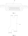
- a waterproof and sealing design that can reach at least the IPX7 level is usually implemented by improving waterproof and sealing performance of a component exposed to a housing of a housing. For example, waterproof and sealing processing is performed on an existing interface 20 (as shown in FIG. 1 ), so that a terminal has good waterproof performance. Although this can improve the waterproof performance of the terminal, this also leads to high waterproof and sealing costs of the terminal, and is not conducive to controlling manufacturing costs of the terminal.
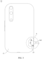
- an embodiment of this application provides a terminal device 10, to implement a high waterproof and sealing level at low costs.
- the high waterproof and sealing level specifically refers to at least an IPX7 level.
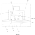
- the terminal device 10 provided in this embodiment of this application includes a housing 11, a circuit board 112, and an interface component 14.
- the terminal device 10 may be a mobile terminal device 10, for example, a mobile phone, a tablet, or a notebook computer, or may be a fixed terminal device 10, for example, a microcomputer, a workstation, a communication room data center, or a communication base station.
- the housing 11 refers to an outer shell of the terminal device 10, or may refer to an internal housing of the terminal device 10.
- the circuit board 112 is disposed in the housing 11. In this embodiment, the circuit board 112 may be a small board in the terminal device 10.
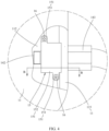
- an isolation groove 13 is formed in an inner wall of the housing 11, the isolation groove 13 has a first opening 131, and the first opening 131 is exposed to the housing 11.
- the inner wall of the housing 11 may refer to a surface that is of a bezel 115 of the housing 11 and that faces inner space of the housing 11, or may refer to a surface that is of a bottom surface or the like of the housing 11 and that faces the inner space of the housing 11 when the housing 11 is placed horizontally.
- the first opening 131 of the isolation groove 13 may be disposed to face the bezel 115 of the housing 11.
- the interface component 14 is sealed in the isolation groove 13 through a sealing kit 15.
- the interface component 14 is electrically connected to the circuit board 112, and an interface end 141 of the interface component 14 is exposed to the first opening 131.
- the interface component 14 may be a USB interface, a Micro-USB interface, a Type-C interface, or the like.
- the isolation groove 13 has a second opening 132, and the second opening 132 is located in the housing 11.
- the sealing kit 15 includes a sealing plate 151, and the sealing plate 151 is disposed at the second opening 132 and is configured to seal the second opening 132.
- the sealing plate 151 may be sealed in the second opening 132, or may cover a peripheral edge of the second opening 132.
- the sealing plate 151 is sealed in the second opening 132, so that sealing of the interface component 14 in the isolation groove 13 is simply and reliably implemented, and reliable isolation between the interface component 14 and the circuit board 112 in the housing 11 of the terminal is also implemented.
- the second opening 132 also facilitates an electrical connection between a flexible printed circuit 142 of the interface component 14 and the circuit board 112 in the housing 11 of the terminal. Electrically connected components such as the flexible printed circuit P60035/EP 142 of the interface component 14 may pass through the second opening 132 and the sealing plate 151, to be electrically connected to the circuit board 112 in the housing 11 of the terminal.
- the sealing plate 151 includes a main body 152 and engaging lugs 153.
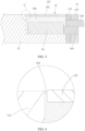
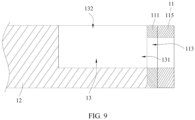
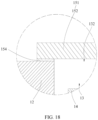
- the main body 152 is disposed at the second opening 132, and a gap 121 (as shown in FIG. 7 ) is formed between a peripheral edge of the main body 152 and a groove wall of the isolation groove 13.
- the gap 121 is filled with a waterproof glue 154 (as shown in FIG. 6 ), and the engaging lugs 153 are connected to an edge of the main body 152 and are connected to the circuit board 112 through screws 16.
- the sealing plate 151 specifically includes the main body 152 and the engaging lugs 153.
- the main body 152 may be completely disposed in the isolation groove 13, or may be semi-submerged in the isolation groove 13.
- an end surface on which the second opening 132 is disposed on a small board has good flatness, so that the sealing plate 151 does not occupy assembly space inside the housing 11, and this is conducive to a lightweight design of the terminal device 10.
- the gap 121 between the main body 152 and the groove wall of the isolation groove 13 is filled with the waterproof glue 154, so that reliable sealing of the isolation groove 13 is implemented.
- the engaging lugs 153 are connected to the circuit board 112 through the screws 16, so that a reliable connection between the sealing plate 151 and the circuit board 112 is implemented, and the sealing plate 151 has better assembly stability in the housing 11 of the terminal.
- the waterproof glue 154 may be filled in the gap 121 between the main body 152 and the groove wall of the isolation groove 13.
- the engaging lugs 153 may be flake-like objects connected to the edge of the main body 152, and the engaging lugs 153 may be integrally formed with the main body 152, so that connection strength between the engaging lugs 153 and the main body 152 may be improved, and overall manufacturing costs of the sealing plate 151 can be reduced.
- a support stand 122 is disposed at a position that is on a groove wall of the isolation groove 13 and that is close to the second opening 132, and the peripheral edge of the main body 152 is disposed on the support stand 122.
- the support stand 122 is disposed on the groove wall of the isolation groove 13.
- the main body 152 when the main body 152 is disposed in the isolation groove 13, the main body 152 can be stably limited in the isolation groove 13 through pressing of the support stand 122.
- the main body 152 can be limited in the isolation groove 13 without pressing the main body 152 against the interface component 14, thereby improving assembly stability of the main body 152 in the isolation groove 13.
- the waterproof glue 154 may also be filled between the main body 152 and the support stand 122, so that the main body 152 and the support stand 122 have better connection strength, and sealing performance of the sealing plate 15 to the isolation groove 13 is also improved.
- the support stand 122 may be suspended on the groove wall of the isolation groove 13, so that the support stand 122 may not occupy assembly space inside the isolation groove 13, thereby leaving enough space for mounting the interface component 14 in the isolation groove 13.
- the support stand 122 may alternatively be formed by forming a step at a position that is on the groove wall of the isolation groove 13 and that is close to the second opening 132. In this case, when the support stand 122 presses against the main body 152, stability of supporting the main body 152 can be well improved.
- the sealing plate 151 includes the main body 152 and the engaging lugs 153.
- the main body 152 is disposed at the second opening 132.
- the support stand 122 is disposed at the position that is on the groove wall of the isolation groove 13 and that is close to the second opening 132, and the peripheral edge of the main body 152 is disposed on the support stand 122.
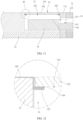
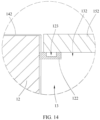
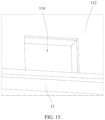
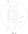
- a first caulking groove 123 (as shown in FIG. 13 ) is disposed on a surface of the support stand 122, and a first sealing strip 124 (as shown in FIG. 14 ) is disposed in the first caulking groove 123.
- the first sealing strip 124 presses against a surface that is of the main body 152 and that faces the isolation groove 13.
- the engaging lugs 153 are connected to the edge of the main body 152 and are connected to the circuit board 112 through the screws 16.
- the main body 152 and the isolation groove 13 may be sealed without the waterproof glue 154, but the first sealing strip 124 may be disposed in the first caulking groove 123 disposed on the surface of the support stand 122, so that the first sealing strip 124 presses against the main body 152.
- the engaging lugs 153 are connected to the circuit board 112 through the screws 16, when the first sealing strip 124 applies an elastic force to press against the main body 152, the engaging lugs 153 can provide a reactive force for the main body 152, so that the main body 152 steadily presses against the first sealing strip 124, thereby implementing sealing of the isolation groove 13 by the main body 152. Therefore, the sealing plate 151 can be detachably connected to the circuit board 112, to facilitate removal and replacement of the sealing plate 151, and avoid use of the waterproof glue 154. Therefore, the terminal device 10 has lower waterproof implementation costs.
- a projection 12 is formed on the inner wall of the housing 11, and the isolation groove 13 is disposed on the projection 12.
- the isolation groove 13 may be directly disposed on the inner wall of the housing 11.
- the housing 11 needs to be sufficiently thick. However, if the thickness of the housing 11 is too thick, it is not conducive to control manufacturing costs of the housing, and the housing 11 occupies assembly space of an electronic component in the housing 11.
- the projection 12 is formed on the inner wall of the housing 11, and then the isolation groove 13 is disposed in the projection 12. In this way, the projection 12 only occupies local space of the housing 11, and assembly space of the electrical component inside the housing 11 is not affected. In addition, there is no need to increase thickness of a side wall of the housing 11, to well reduce manufacturing costs of the housing 11.
- the projection 12 and the housing 11 may be die-cast integrally, forged integrally, or injection molded integrally, so that strength of a junction between the projection 12 and the housing 11 can be improved, and manufacturing costs of the projection 12 and the housing 11 are reduced.
- a clearance configured to pass through the projection 12 is disposed on a circuit board 112.
- the sealing plate 151 includes the main body 152 and the engaging lugs 153.
- the main body 152 covers the second opening 132.
- the peripheral edge of the main body 152 and a position that is on the projection 12 and that is located at the peripheral edge of the second opening 132 are hermetically connected.
- the engaging lugs 153 are connected to the edge of the main body 152 and are connected to the circuit board 112 through the screws 16.
- the main body 152 covers the second opening 132.
- the main body 152 completely covers the second opening 132, instead of being disposed in the second opening 132.
- the peripheral edge of the main body 152 and the position that is on the projection 12 and that is located at the peripheral edge of the second opening 132 are hermetically connected, thereby implementing sealing of the isolation groove 13 by the main body 152.
- the main body 152 does not need to be disposed in the isolation groove 13, so that a strict requirement for dimensional tolerance of the main body 152 may be avoided, processing difficulty of the main body 152 is reduced, and processing and manufacturing costs of the main body 152 are reduced.
- the main body 152 and the position that is of the projection 12 and that is located at the peripheral edge of the second opening 132 are hermetically connected through the waterproof glue 154.
- a peripheral edge of the main body 152 and a circuit board 112 and the peripheral edge of the second opening 132 are sealed through a glue dispensing operation of the waterproof glue 154.
- the waterproof glue 154 may be simply distributed in a position that is of the projection 12 and that is located at the peripheral edge of the second opening 132.
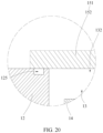
- a second caulking groove 125 is disposed at a position that is on the projection 12 and that is at the peripheral edge of the second opening 132.
- a second sealing strip 126 is disposed in the second caulking groove 125, and the second sealing strip 126 presses against the surface that is of the main body 152 and that faces the isolation groove 13.
- the main body 152 of the sealing plate 151 may be hermetically connected to the projection 12through pressing of the second sealing strip 126. Therefore, the sealing plate 151 can be detachably connected to the projection 12, to facilitate removal and replacement of the sealing plate 151, and avoid use of the waterproof glue 154, so that the terminal device 10 has lower waterproof implementation costs.
- a quantity of engaging lugs 153 is two, and two engaging lugs 153 are respectively connected to edges of two opposite sides of the main body 152.
- the quantity of the engaging lugs 153 is limited to two, and the two engaging lugs 153 are respectively connected to the edges of the two opposite sides of the main body 152, so that the two engaging lugs 153 can exert forces on the two opposite sides of the main body 152, and the main body 152 can be stably disposed in the housing 11 of the terminal.
- the two engaging lugs 153 are respectively located at two opposite ends of a diagonal line of the main body 152. Specifically, on the basis of the foregoing embodiment, the two engaging lugs 153 are respectively located at the two opposite ends of the diagonal line of the main body 152.
- the two engaging lugs 153 are respectively located on two opposite sides in a width direction of the main body 152, and the two engaging lugs 153 are also respectively located on two opposite sides in a length direction of the main body 152, so that the two engaging lugs 153 can exert forces on the two opposite sides in the length direction and the two opposite sides in the width direction of the main body 152, and the main body 152 can be more stably disposed in the housing 11 of the terminal.
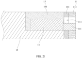
- the sealing kit 15 includes a sealing glue 155, and the sealing glue 155 is filled in the isolation groove 13.
- the interface component 14 is sealed in the sealing glue 155.
- the sealing kit 15 is the sealing glue 155, and the sealing glue 155 is directly filled in the isolation groove 13, so that the interface component 14 is sealed in the isolation groove 13. In this way, sealing costs of the interface component 14 are better reduced, and overall waterproof implementation costs of the terminal device 10 are better reduced.
- the flexible printed circuit 142 of the interface component 14 in this embodiment of this application is directly connected to a BTB interface on the circuit board 112, so the flexible printed circuit 142 is separately configured for the interface component 14, thus facilitating rapid assembly of the interface component 14 in the housing 11.
- the flexible printed circuit 142 of the interface component 14 may be connected to the BTB interface on the circuit board 112 in advance, and then the sealing glue 155 is filled into the isolation groove 13.
- the sealing glue 155 may also protect and fasten the flexible printed circuit 142.
- the sealing glue 155 and the waterproof glue 154 each may be an instantaneous adhesive, a UV (Ultraviolet Ray) glue, a hot melt adhesive, or the like.
Landscapes
- Engineering & Computer Science (AREA)
- Computer Hardware Design (AREA)
- Theoretical Computer Science (AREA)
- Signal Processing (AREA)
- General Engineering & Computer Science (AREA)
- Microelectronics & Electronic Packaging (AREA)
- Human Computer Interaction (AREA)
- Physics & Mathematics (AREA)
- General Physics & Mathematics (AREA)
- Casings For Electric Apparatus (AREA)
Claims (12)
- Ein Endgerät, umfassend:ein Gehäuse (11), wobei eine Isolationsnut (13) in einer Innenwand des Gehäuses (11) ausgebildet ist, die Isolationsnut (13) eine erste Öffnung (131) aufweist und die erste Öffnung (131) dem Gehäuse (11) ausgesetzt ist;eine Leiterplatte (112), wobei die Leiterplatte (112) im Gehäuse (11) angeordnet ist; undeine Schnittstellenkomponente (14), wobei die Schnittstellenkomponente (14) durch ein Dichtungskit (15) in der Isolationsnut (13) abgedichtet ist, die Schnittstellenkomponente (14) elektrisch mit der Leiterplatte (112) verbunden ist und ein Schnittstellenende (141) der Schnittstellenkomponente (14) der ersten Öffnung (131) ausgesetzt ist;wobei die Isolationsnut (13) eine zweite Öffnung (132) aufweist, die zweite Öffnung (132) sich im Inneren des Gehäuses (11) befindet, das Dichtungskit (15) eine Dichtplatte (151) umfasst, und die Dichtplatte (151) an der zweiten Öffnung (132) angeordnet ist und dazu konfiguriert ist, die zweite Öffnung (132) abzudichten, undwobei das Dichtungsset (15) weiterhin einen Dichtkleber (155) umfasst, der Dichtkleber (155) in die Isolationsnut (13) gefüllt ist und die Schnittstellenkomponente (14) im Dichtkleber (155) abgedichtet ist.
- Das Endgerät nach Anspruch 1, wobei die Dichtplatte (151) einen Hauptkörper (152) und Eingriffslaschen (153) umfasst, der Hauptkörper (152) an der zweiten Öffnung (132) angeordnet ist, ein Spalt (121) zwischen einem Rand des Hauptkörpers (152) und einer Rillenwand der Isolationsrille (13) gebildet wird, der Spalt (121) mit einem wasserdichten Kleber (154) gefüllt ist, die Eingriffslaschen (153) mit einem Rand des Hauptkörpers (152) verbunden sind und durch Schrauben (16) mit der Leiterplatte (112) verbunden sind.
- Das Endgerät nach Anspruch 2, wobei ein Stützständer (122) an einer Position angeordnet ist, die sich an der Nutwand der Isolationsnut (13) und in der Nähe der zweiten Öffnung (132) befindet, und der Rand des Hauptkörpers (152) auf dem Stützständer (122) angeordnet ist.
- Das Endgerät nach Anspruch 1, wobei die Dichtplatte (151) einen Hauptkörper (152) und Eingriffslaschen (153) umfasst, der Hauptkörper (152) an der zweiten Öffnung (132) angeordnet ist, ein Stützständer (122) an einer Position angeordnet ist, die sich an einer Nutwand der Isolationsnut (13) und in der Nähe der zweiten Öffnung (132) befindet, ein Rand des Hauptkörpers (152) auf dem Stützständer (122) angeordnet ist, eine erste Dichtungsnut (123) auf einer Oberfläche des Stützständers (122) angeordnet ist, ein erster Dichtungsstreifen (124) in der ersten Dichtungsnut (123) angeordnet ist, der erste Dichtungsstreifen (124) gegen eine Oberfläche des Hauptkörpers (152) drückt, die der Isolationsnut (13) zugewandt ist, und die Eingriffslaschen (153) mit einem Rand des Hauptkörpers (152) verbunden sind und durch Schrauben (16) mit der Leiterplatte (112) verbunden sind.
- Das Endgerät nach einem der Ansprüche 2 bis 4, wobei eine Projektion (12) an der Innenwand des Gehäuses (11) ausgebildet ist und die Isolationsnut (13) in der Projektion (12) angeordnet ist.
- Das Endgerät nach Anspruch 5, wobei die Dichtplatte (151) den Hauptkörper (152) und die Eingriffslaschen (153) umfasst, der Hauptkörper (152) die zweite Öffnung (132) abdeckt, der Rand des Hauptkörpers (152) und eine Position, die sich auf dem Vorsprung (12) befindet und die sich am Rand der zweiten Öffnung (132) befindet, hermetisch verbunden sind, und die Eingriffslaschen (153) mit dem Rand des Hauptkörpers (152) verbunden sind und durch die Schrauben (16) mit der Leiterplatte (112) verbunden sind.
- Das Endgerät nach Anspruch 6, wobei der Hauptkörper (152) und die Position, die sich am Vorsprung (12) und am Rand der zweiten Öffnung (132) befindet, durch den wasserdichten Kleber (154) hermetisch verbunden sind.
- Das Endgerät nach Anspruch 6, wobei eine zweite Verstemmnut (125) an einer Position angeordnet ist, die sich auf dem Vorsprung (12) und am Rand der zweiten Öffnung (132) befindet, ein zweiter Dichtstreifen (126) in der zweiten Verstemmnut (125) angeordnet ist und der zweite Dichtstreifen (126) gegen die Oberfläche des Hauptkörpers (152) drückt, die der Isolationsnut (13) zugewandt ist.
- Das Endgerät nach einem der Ansprüche 2 bis 8, wobei die Schnittstellenkomponente (14) eine flexible Leiterplatte (142) aufweist, und die flexible Leiterplatte (142) aus der Isolationsnut (13) herausragt und mit einem Board-to-Board-Steckverbinder der Leiterplatte (112) verbunden ist.
- Das Endgerät nach einem der Ansprüche 2 bis 8, wobei die Anzahl der Eingriffslaschen (153) zwei beträgt und die beiden Eingriffslaschen (153) jeweils mit den Kanten zweier gegenüberliegender Seiten des Hauptkörpers (152) verbunden sind.
- Das Endgerät nach einem der Ansprüche 2 bis 8, wobei die beiden Eingriffslaschen (153) jeweils an zwei gegenüberliegenden Enden einer Diagonale des Hauptkörpers (152) angeordnet sind.
- Das Endgerät nach einem der Ansprüche 1 bis 11, wobei die Schnittstellenkomponente (14) eine universelle serielle Bus-Schnittstelle ist.
Applications Claiming Priority (2)
| Application Number | Priority Date | Filing Date | Title |
|---|---|---|---|
| CN202110749171.4A CN113613446B (zh) | 2021-07-01 | 2021-07-01 | 终端设备 |
| PCT/CN2022/090338 WO2023273588A1 (zh) | 2021-07-01 | 2022-04-29 | 终端设备 |
Publications (3)
| Publication Number | Publication Date |
|---|---|
| EP4138527A1 EP4138527A1 (de) | 2023-02-22 |
| EP4138527A4 EP4138527A4 (de) | 2023-12-13 |
| EP4138527B1 true EP4138527B1 (de) | 2025-02-26 |
Family
ID=78337182
Family Applications (1)
| Application Number | Title | Priority Date | Filing Date |
|---|---|---|---|
| EP22789821.0A Active EP4138527B1 (de) | 2021-07-01 | 2022-04-29 | Endgerätevorrichtung |
Country Status (4)
| Country | Link |
|---|---|
| US (1) | US12477052B2 (de) |
| EP (1) | EP4138527B1 (de) |
| CN (1) | CN113613446B (de) |
| WO (1) | WO2023273588A1 (de) |
Families Citing this family (1)
| Publication number | Priority date | Publication date | Assignee | Title |
|---|---|---|---|---|
| CN113613446B (zh) | 2021-07-01 | 2022-09-23 | 荣耀终端有限公司 | 终端设备 |
Citations (1)
| Publication number | Priority date | Publication date | Assignee | Title |
|---|---|---|---|---|
| DE10221303A1 (de) * | 2002-05-14 | 2003-11-27 | Valeo Schalter & Sensoren Gmbh | Sensor, insbesondere Ultraschallsensor, und Verfahren zur Herstellung |
Family Cites Families (23)
| Publication number | Priority date | Publication date | Assignee | Title |
|---|---|---|---|---|
| JP4625037B2 (ja) * | 2007-03-05 | 2011-02-02 | アール・ビー・コントロールズ株式会社 | 浴室用電子機器 |
| CN102005666B (zh) | 2009-08-31 | 2014-04-16 | 深圳富泰宏精密工业有限公司 | 接口组件及应用该接口组件的便携式电子装置 |
| JP5099566B2 (ja) * | 2010-09-06 | 2012-12-19 | Smk株式会社 | 防水機能付きコネクタ |
| CN102843889B (zh) * | 2012-09-10 | 2016-06-08 | 惠州Tcl移动通信有限公司 | 一种usb防水组件以及便携式电子设备 |
| CN203055747U (zh) * | 2013-01-08 | 2013-07-10 | 乐清市新驰电气科技有限公司 | 双接口封闭式隔离开关 |
| GB2518869B (en) * | 2013-10-03 | 2016-12-28 | Valeo Powertrain Energy Conv As | Electronic enclosure device |
| US9723737B2 (en) * | 2014-01-07 | 2017-08-01 | Samsung Electronics Co., Ltd. | Electronic device having waterproof structure |
| JP2015225712A (ja) * | 2014-05-26 | 2015-12-14 | 株式会社エクセル電子 | 電子機器の防水接続器具及び電子機器 |
| TWM510512U (zh) * | 2015-03-27 | 2015-10-11 | Uniform Ind Corp | 防側錄讀卡裝置 |
| CN205945857U (zh) * | 2016-08-29 | 2017-02-08 | 京东方科技集团股份有限公司 | 移动终端 |
| CN206181117U (zh) * | 2016-11-04 | 2017-05-17 | 广东欧珀移动通信有限公司 | 终端的外壳组件及终端 |
| CN206181146U (zh) * | 2016-11-04 | 2017-05-17 | 广东欧珀移动通信有限公司 | 终端的外壳组件及终端 |
| CN106375523B (zh) * | 2016-11-04 | 2017-11-10 | 广东欧珀移动通信有限公司 | 终端的外壳组件及终端 |
| CN108206366B (zh) * | 2016-12-16 | 2021-07-20 | 深圳市长盈精密技术股份有限公司 | 一种防水金属壳体 |
| CN108206874B (zh) * | 2016-12-16 | 2021-07-20 | 深圳市长盈精密技术股份有限公司 | 一种手机壳体 |
| CN106848732A (zh) * | 2017-03-24 | 2017-06-13 | 东莞立德精密工业有限公司 | 电路板连接器 |
| CN108173058A (zh) * | 2017-12-21 | 2018-06-15 | 广东欧珀移动通信有限公司 | 连接器防水组件及移动终端 |
| CN108281843B (zh) * | 2018-01-26 | 2021-05-21 | 努比亚技术有限公司 | Usb防水接口结构及具有该usb防水接口的移动终端 |
| KR102372641B1 (ko) * | 2018-11-30 | 2022-03-10 | 삼성전자주식회사 | 실링 구조 및 이를 포함하는 전자 장치 |
| CN111446585A (zh) * | 2019-01-16 | 2020-07-24 | 北京小米移动软件有限公司 | Usb防水结构和具有该usb防水结构的终端设备 |
| CN110716618A (zh) * | 2019-11-28 | 2020-01-21 | 中煤北京煤矿机械有限责任公司 | 一种矿用隔爆兼本质安全型监控主机 |
| CN212967921U (zh) * | 2020-09-30 | 2021-04-13 | 东莞新能安科技有限公司 | 具有密封结构的电池 |
| CN113613446B (zh) * | 2021-07-01 | 2022-09-23 | 荣耀终端有限公司 | 终端设备 |
-
2021
- 2021-07-01 CN CN202110749171.4A patent/CN113613446B/zh active Active
-
2022
- 2022-04-29 EP EP22789821.0A patent/EP4138527B1/de active Active
- 2022-04-29 US US17/924,238 patent/US12477052B2/en active Active
- 2022-04-29 WO PCT/CN2022/090338 patent/WO2023273588A1/zh not_active Ceased
Patent Citations (1)
| Publication number | Priority date | Publication date | Assignee | Title |
|---|---|---|---|---|
| DE10221303A1 (de) * | 2002-05-14 | 2003-11-27 | Valeo Schalter & Sensoren Gmbh | Sensor, insbesondere Ultraschallsensor, und Verfahren zur Herstellung |
Also Published As
| Publication number | Publication date |
|---|---|
| EP4138527A1 (de) | 2023-02-22 |
| CN113613446B (zh) | 2022-09-23 |
| WO2023273588A1 (zh) | 2023-01-05 |
| EP4138527A4 (de) | 2023-12-13 |
| US20240171666A1 (en) | 2024-05-23 |
| US12477052B2 (en) | 2025-11-18 |
| CN113613446A (zh) | 2021-11-05 |
Similar Documents
| Publication | Publication Date | Title |
|---|---|---|
| US6537085B2 (en) | Portable electronic apparatus having external connector fixed at internal circuit board | |
| EP3255963B1 (de) | Elektronische vorrichtung | |
| EP4576444A1 (de) | Verbinder und elektronische vorrichtung | |
| EP4138527B1 (de) | Endgerätevorrichtung | |
| CN205071069U (zh) | 移动终端 | |
| CN107643635B (zh) | 显示装置及其接地装置 | |
| HK40079001B (en) | Terminal device | |
| CN108206874B (zh) | 一种手机壳体 | |
| HK40079001A (en) | Terminal device | |
| CN222546721U (zh) | 一种连接器组件 | |
| CN210865410U (zh) | 显示装置 | |
| WO2021184900A1 (zh) | 显示装置的后壳及显示装置 | |
| CN215269344U (zh) | 屏蔽机箱及屏蔽系统 | |
| CN217881254U (zh) | 电子设备 | |
| CN113543617B (zh) | 电磁兼容性屏蔽装置及电子设备 | |
| CN116320256A (zh) | 电子设备 | |
| CN223566257U (zh) | 显示设备及显示系统 | |
| CN209897468U (zh) | 密封结构及电子设备 | |
| CN221551431U (zh) | 一种显示屏安装结构 | |
| CN219961098U (zh) | 一种移动终端 | |
| CN223006417U (zh) | 电子设备 | |
| CN219961071U (zh) | 一种显示屏 | |
| CN224124431U (zh) | 终端设备 | |
| CN221262628U (zh) | 电池模组及电子设备 | |
| CN223428508U (zh) | 外挂式电子摄像头模组及电子设备 |
Legal Events
| Date | Code | Title | Description |
|---|---|---|---|
| STAA | Information on the status of an ep patent application or granted ep patent |
Free format text: STATUS: UNKNOWN |
|
| STAA | Information on the status of an ep patent application or granted ep patent |
Free format text: STATUS: THE INTERNATIONAL PUBLICATION HAS BEEN MADE |
|
| PUAI | Public reference made under article 153(3) epc to a published international application that has entered the european phase |
Free format text: ORIGINAL CODE: 0009012 |
|
| STAA | Information on the status of an ep patent application or granted ep patent |
Free format text: STATUS: REQUEST FOR EXAMINATION WAS MADE |
|
| 17P | Request for examination filed |
Effective date: 20221026 |
|
| AK | Designated contracting states |
Kind code of ref document: A1 Designated state(s): AL AT BE BG CH CY CZ DE DK EE ES FI FR GB GR HR HU IE IS IT LI LT LU LV MC MK MT NL NO PL PT RO RS SE SI SK SM TR |
|
| REG | Reference to a national code |
Ref country code: HK Ref legal event code: DE Ref document number: 40079001 Country of ref document: HK |
|
| REG | Reference to a national code |
Ref country code: DE Ref legal event code: R079 Free format text: PREVIOUS MAIN CLASS: H05K0005060000 Ipc: G06F0001160000 Ref document number: 602022011224 Country of ref document: DE |
|
| A4 | Supplementary search report drawn up and despatched |
Effective date: 20231114 |
|
| RIC1 | Information provided on ipc code assigned before grant |
Ipc: H04M 1/18 20060101ALI20231108BHEP Ipc: H04M 1/02 20060101ALI20231108BHEP Ipc: G06F 1/16 20060101AFI20231108BHEP |
|
| STAA | Information on the status of an ep patent application or granted ep patent |
Free format text: STATUS: EXAMINATION IS IN PROGRESS |
|
| 17Q | First examination report despatched |
Effective date: 20240523 |
|
| GRAP | Despatch of communication of intention to grant a patent |
Free format text: ORIGINAL CODE: EPIDOSNIGR1 |
|
| STAA | Information on the status of an ep patent application or granted ep patent |
Free format text: STATUS: GRANT OF PATENT IS INTENDED |
|
| DAV | Request for validation of the european patent (deleted) | ||
| DAX | Request for extension of the european patent (deleted) | ||
| INTG | Intention to grant announced |
Effective date: 20241008 |
|
| GRAS | Grant fee paid |
Free format text: ORIGINAL CODE: EPIDOSNIGR3 |
|
| GRAA | (expected) grant |
Free format text: ORIGINAL CODE: 0009210 |
|
| STAA | Information on the status of an ep patent application or granted ep patent |
Free format text: STATUS: THE PATENT HAS BEEN GRANTED |
|
| AK | Designated contracting states |
Kind code of ref document: B1 Designated state(s): AL AT BE BG CH CY CZ DE DK EE ES FI FR GB GR HR HU IE IS IT LI LT LU LV MC MK MT NL NO PL PT RO RS SE SI SK SM TR |
|
| REG | Reference to a national code |
Ref country code: GB Ref legal event code: FG4D |
|
| REG | Reference to a national code |
Ref country code: CH Ref legal event code: EP |
|
| REG | Reference to a national code |
Ref country code: DE Ref legal event code: R096 Ref document number: 602022011224 Country of ref document: DE |
|
| REG | Reference to a national code |
Ref country code: IE Ref legal event code: FG4D |
|
| REG | Reference to a national code |
Ref country code: NL Ref legal event code: FP |
|
| PG25 | Lapsed in a contracting state [announced via postgrant information from national office to epo] |
Ref country code: RS Free format text: LAPSE BECAUSE OF FAILURE TO SUBMIT A TRANSLATION OF THE DESCRIPTION OR TO PAY THE FEE WITHIN THE PRESCRIBED TIME-LIMIT Effective date: 20250526 |
|
| PG25 | Lapsed in a contracting state [announced via postgrant information from national office to epo] |
Ref country code: FI Free format text: LAPSE BECAUSE OF FAILURE TO SUBMIT A TRANSLATION OF THE DESCRIPTION OR TO PAY THE FEE WITHIN THE PRESCRIBED TIME-LIMIT Effective date: 20250226 |
|
| PG25 | Lapsed in a contracting state [announced via postgrant information from national office to epo] |
Ref country code: PL Free format text: LAPSE BECAUSE OF FAILURE TO SUBMIT A TRANSLATION OF THE DESCRIPTION OR TO PAY THE FEE WITHIN THE PRESCRIBED TIME-LIMIT Effective date: 20250226 |
|
| PGFP | Annual fee paid to national office [announced via postgrant information from national office to epo] |
Ref country code: DE Payment date: 20250319 Year of fee payment: 4 |
|
| PG25 | Lapsed in a contracting state [announced via postgrant information from national office to epo] |
Ref country code: ES Free format text: LAPSE BECAUSE OF FAILURE TO SUBMIT A TRANSLATION OF THE DESCRIPTION OR TO PAY THE FEE WITHIN THE PRESCRIBED TIME-LIMIT Effective date: 20250226 |
|
| REG | Reference to a national code |
Ref country code: LT Ref legal event code: MG9D |
|
| PG25 | Lapsed in a contracting state [announced via postgrant information from national office to epo] |
Ref country code: NO Free format text: LAPSE BECAUSE OF FAILURE TO SUBMIT A TRANSLATION OF THE DESCRIPTION OR TO PAY THE FEE WITHIN THE PRESCRIBED TIME-LIMIT Effective date: 20250526 Ref country code: IS Free format text: LAPSE BECAUSE OF FAILURE TO SUBMIT A TRANSLATION OF THE DESCRIPTION OR TO PAY THE FEE WITHIN THE PRESCRIBED TIME-LIMIT Effective date: 20250626 |
|
| PG25 | Lapsed in a contracting state [announced via postgrant information from national office to epo] |
Ref country code: HR Free format text: LAPSE BECAUSE OF FAILURE TO SUBMIT A TRANSLATION OF THE DESCRIPTION OR TO PAY THE FEE WITHIN THE PRESCRIBED TIME-LIMIT Effective date: 20250226 |
|
| PG25 | Lapsed in a contracting state [announced via postgrant information from national office to epo] |
Ref country code: PT Free format text: LAPSE BECAUSE OF FAILURE TO SUBMIT A TRANSLATION OF THE DESCRIPTION OR TO PAY THE FEE WITHIN THE PRESCRIBED TIME-LIMIT Effective date: 20250626 Ref country code: LV Free format text: LAPSE BECAUSE OF FAILURE TO SUBMIT A TRANSLATION OF THE DESCRIPTION OR TO PAY THE FEE WITHIN THE PRESCRIBED TIME-LIMIT Effective date: 20250226 |
|
| PG25 | Lapsed in a contracting state [announced via postgrant information from national office to epo] |
Ref country code: BG Free format text: LAPSE BECAUSE OF FAILURE TO SUBMIT A TRANSLATION OF THE DESCRIPTION OR TO PAY THE FEE WITHIN THE PRESCRIBED TIME-LIMIT Effective date: 20250226 Ref country code: GR Free format text: LAPSE BECAUSE OF FAILURE TO SUBMIT A TRANSLATION OF THE DESCRIPTION OR TO PAY THE FEE WITHIN THE PRESCRIBED TIME-LIMIT Effective date: 20250527 |
|
| REG | Reference to a national code |
Ref country code: AT Ref legal event code: MK05 Ref document number: 1771252 Country of ref document: AT Kind code of ref document: T Effective date: 20250226 |
|
| PG25 | Lapsed in a contracting state [announced via postgrant information from national office to epo] |
Ref country code: SE Free format text: LAPSE BECAUSE OF FAILURE TO SUBMIT A TRANSLATION OF THE DESCRIPTION OR TO PAY THE FEE WITHIN THE PRESCRIBED TIME-LIMIT Effective date: 20250226 |
|
| PG25 | Lapsed in a contracting state [announced via postgrant information from national office to epo] |
Ref country code: SM Free format text: LAPSE BECAUSE OF FAILURE TO SUBMIT A TRANSLATION OF THE DESCRIPTION OR TO PAY THE FEE WITHIN THE PRESCRIBED TIME-LIMIT Effective date: 20250226 |
|
| PG25 | Lapsed in a contracting state [announced via postgrant information from national office to epo] |
Ref country code: DK Free format text: LAPSE BECAUSE OF FAILURE TO SUBMIT A TRANSLATION OF THE DESCRIPTION OR TO PAY THE FEE WITHIN THE PRESCRIBED TIME-LIMIT Effective date: 20250226 |
|
| PG25 | Lapsed in a contracting state [announced via postgrant information from national office to epo] |
Ref country code: IT Free format text: LAPSE BECAUSE OF FAILURE TO SUBMIT A TRANSLATION OF THE DESCRIPTION OR TO PAY THE FEE WITHIN THE PRESCRIBED TIME-LIMIT Effective date: 20250226 |
|
| PG25 | Lapsed in a contracting state [announced via postgrant information from national office to epo] |
Ref country code: AT Free format text: LAPSE BECAUSE OF FAILURE TO SUBMIT A TRANSLATION OF THE DESCRIPTION OR TO PAY THE FEE WITHIN THE PRESCRIBED TIME-LIMIT Effective date: 20250226 |
|
| PG25 | Lapsed in a contracting state [announced via postgrant information from national office to epo] |
Ref country code: EE Free format text: LAPSE BECAUSE OF FAILURE TO SUBMIT A TRANSLATION OF THE DESCRIPTION OR TO PAY THE FEE WITHIN THE PRESCRIBED TIME-LIMIT Effective date: 20250226 Ref country code: CZ Free format text: LAPSE BECAUSE OF FAILURE TO SUBMIT A TRANSLATION OF THE DESCRIPTION OR TO PAY THE FEE WITHIN THE PRESCRIBED TIME-LIMIT Effective date: 20250226 |
|
| PG25 | Lapsed in a contracting state [announced via postgrant information from national office to epo] |
Ref country code: RO Free format text: LAPSE BECAUSE OF FAILURE TO SUBMIT A TRANSLATION OF THE DESCRIPTION OR TO PAY THE FEE WITHIN THE PRESCRIBED TIME-LIMIT Effective date: 20250226 |
|
| PG25 | Lapsed in a contracting state [announced via postgrant information from national office to epo] |
Ref country code: SK Free format text: LAPSE BECAUSE OF FAILURE TO SUBMIT A TRANSLATION OF THE DESCRIPTION OR TO PAY THE FEE WITHIN THE PRESCRIBED TIME-LIMIT Effective date: 20250226 |
|
| REG | Reference to a national code |
Ref country code: CH Ref legal event code: H13 Free format text: ST27 STATUS EVENT CODE: U-0-0-H10-H13 (AS PROVIDED BY THE NATIONAL OFFICE) Effective date: 20251125 |
|
| REG | Reference to a national code |
Ref country code: DE Ref legal event code: R097 Ref document number: 602022011224 Country of ref document: DE |
|
| PG25 | Lapsed in a contracting state [announced via postgrant information from national office to epo] |
Ref country code: LU Free format text: LAPSE BECAUSE OF NON-PAYMENT OF DUE FEES Effective date: 20250429 |
|
| PG25 | Lapsed in a contracting state [announced via postgrant information from national office to epo] |
Ref country code: MC Free format text: LAPSE BECAUSE OF FAILURE TO SUBMIT A TRANSLATION OF THE DESCRIPTION OR TO PAY THE FEE WITHIN THE PRESCRIBED TIME-LIMIT Effective date: 20250226 |
|
| REG | Reference to a national code |
Ref country code: BE Ref legal event code: MM Effective date: 20250430 |
|
| PLBE | No opposition filed within time limit |
Free format text: ORIGINAL CODE: 0009261 |
|
| STAA | Information on the status of an ep patent application or granted ep patent |
Free format text: STATUS: NO OPPOSITION FILED WITHIN TIME LIMIT |
|
| PG25 | Lapsed in a contracting state [announced via postgrant information from national office to epo] |
Ref country code: FR Free format text: LAPSE BECAUSE OF NON-PAYMENT OF DUE FEES Effective date: 20250430 |
|
| PG25 | Lapsed in a contracting state [announced via postgrant information from national office to epo] |
Ref country code: BE Free format text: LAPSE BECAUSE OF NON-PAYMENT OF DUE FEES Effective date: 20250430 |
|
| PG25 | Lapsed in a contracting state [announced via postgrant information from national office to epo] |
Ref country code: CH Free format text: LAPSE BECAUSE OF NON-PAYMENT OF DUE FEES Effective date: 20250430 |
|
| 26N | No opposition filed |
Effective date: 20251127 |
|
| PGFP | Annual fee paid to national office [announced via postgrant information from national office to epo] |
Ref country code: GB Payment date: 20260312 Year of fee payment: 5 |
|
| PG25 | Lapsed in a contracting state [announced via postgrant information from national office to epo] |
Ref country code: IE Free format text: LAPSE BECAUSE OF NON-PAYMENT OF DUE FEES Effective date: 20250429 |
|
| PGFP | Annual fee paid to national office [announced via postgrant information from national office to epo] |
Ref country code: NL Payment date: 20260317 Year of fee payment: 5 |