EP4576444A1 - Verbinder und elektronische vorrichtung - Google Patents
Verbinder und elektronische vorrichtung Download PDFInfo
- Publication number
- EP4576444A1 EP4576444A1 EP23870734.3A EP23870734A EP4576444A1 EP 4576444 A1 EP4576444 A1 EP 4576444A1 EP 23870734 A EP23870734 A EP 23870734A EP 4576444 A1 EP4576444 A1 EP 4576444A1
- Authority
- EP
- European Patent Office
- Prior art keywords
- electrical connection
- socket
- groove
- base
- board
- Prior art date
- Legal status (The legal status is an assumption and is not a legal conclusion. Google has not performed a legal analysis and makes no representation as to the accuracy of the status listed.)
- Pending
Links
Images





Classifications
-
- H—ELECTRICITY
- H01—ELECTRIC ELEMENTS
- H01R—ELECTRICALLY-CONDUCTIVE CONNECTIONS; STRUCTURAL ASSOCIATIONS OF A PLURALITY OF MUTUALLY-INSULATED ELECTRICAL CONNECTING ELEMENTS; COUPLING DEVICES; CURRENT COLLECTORS
- H01R13/00—Details of coupling devices of the kinds covered by groups H01R12/70 or H01R24/00 - H01R33/00
- H01R13/46—Bases; Cases
-
- H—ELECTRICITY
- H04—ELECTRIC COMMUNICATION TECHNIQUE
- H04M—TELEPHONIC COMMUNICATION
- H04M1/00—Substation equipment, e.g. for use by subscribers
- H04M1/02—Constructional features of telephone sets
- H04M1/0202—Portable telephone sets, e.g. cordless phones, mobile phones or bar type handsets
- H04M1/026—Details of the structure or mounting of specific components
- H04M1/0274—Details of the structure or mounting of specific components for an electrical connector module
-
- H—ELECTRICITY
- H01—ELECTRIC ELEMENTS
- H01R—ELECTRICALLY-CONDUCTIVE CONNECTIONS; STRUCTURAL ASSOCIATIONS OF A PLURALITY OF MUTUALLY-INSULATED ELECTRICAL CONNECTING ELEMENTS; COUPLING DEVICES; CURRENT COLLECTORS
- H01R13/00—Details of coupling devices of the kinds covered by groups H01R12/70 or H01R24/00 - H01R33/00
- H01R13/73—Means for mounting coupling parts to apparatus or structures, e.g. to a wall
- H01R13/74—Means for mounting coupling parts in openings of a panel
- H01R13/748—Means for mounting coupling parts in openings of a panel using one or more screws
-
- H—ELECTRICITY
- H01—ELECTRIC ELEMENTS
- H01R—ELECTRICALLY-CONDUCTIVE CONNECTIONS; STRUCTURAL ASSOCIATIONS OF A PLURALITY OF MUTUALLY-INSULATED ELECTRICAL CONNECTING ELEMENTS; COUPLING DEVICES; CURRENT COLLECTORS
- H01R12/00—Structural associations of a plurality of mutually-insulated electrical connecting elements, specially adapted for printed circuits, e.g. printed circuit boards [PCB], flat or ribbon cables, or like generally planar structures, e.g. terminal strips, terminal blocks; Coupling devices specially adapted for printed circuits, flat or ribbon cables, or like generally planar structures; Terminals specially adapted for contact with, or insertion into, printed circuits, flat or ribbon cables, or like generally planar structures
- H01R12/70—Coupling devices
- H01R12/71—Coupling devices for rigid printing circuits or like structures
- H01R12/72—Coupling devices for rigid printing circuits or like structures coupling with the edge of the rigid printed circuits or like structures
- H01R12/722—Coupling devices for rigid printing circuits or like structures coupling with the edge of the rigid printed circuits or like structures coupling devices mounted on the edge of the printed circuits
-
- H—ELECTRICITY
- H01—ELECTRIC ELEMENTS
- H01R—ELECTRICALLY-CONDUCTIVE CONNECTIONS; STRUCTURAL ASSOCIATIONS OF A PLURALITY OF MUTUALLY-INSULATED ELECTRICAL CONNECTING ELEMENTS; COUPLING DEVICES; CURRENT COLLECTORS
- H01R13/00—Details of coupling devices of the kinds covered by groups H01R12/70 or H01R24/00 - H01R33/00
- H01R13/02—Contact members
-
- H—ELECTRICITY
- H01—ELECTRIC ELEMENTS
- H01R—ELECTRICALLY-CONDUCTIVE CONNECTIONS; STRUCTURAL ASSOCIATIONS OF A PLURALITY OF MUTUALLY-INSULATED ELECTRICAL CONNECTING ELEMENTS; COUPLING DEVICES; CURRENT COLLECTORS
- H01R13/00—Details of coupling devices of the kinds covered by groups H01R12/70 or H01R24/00 - H01R33/00
- H01R13/46—Bases; Cases
- H01R13/52—Dustproof, splashproof, drip-proof, waterproof, or flameproof cases
-
- H—ELECTRICITY
- H01—ELECTRIC ELEMENTS
- H01R—ELECTRICALLY-CONDUCTIVE CONNECTIONS; STRUCTURAL ASSOCIATIONS OF A PLURALITY OF MUTUALLY-INSULATED ELECTRICAL CONNECTING ELEMENTS; COUPLING DEVICES; CURRENT COLLECTORS
- H01R13/00—Details of coupling devices of the kinds covered by groups H01R12/70 or H01R24/00 - H01R33/00
- H01R13/73—Means for mounting coupling parts to apparatus or structures, e.g. to a wall
- H01R13/74—Means for mounting coupling parts in openings of a panel
-
- H—ELECTRICITY
- H01—ELECTRIC ELEMENTS
- H01R—ELECTRICALLY-CONDUCTIVE CONNECTIONS; STRUCTURAL ASSOCIATIONS OF A PLURALITY OF MUTUALLY-INSULATED ELECTRICAL CONNECTING ELEMENTS; COUPLING DEVICES; CURRENT COLLECTORS
- H01R24/00—Two-part coupling devices, or either of their cooperating parts, characterised by their overall structure
- H01R24/60—Contacts spaced along planar side wall transverse to longitudinal axis of engagement
-
- H—ELECTRICITY
- H04—ELECTRIC COMMUNICATION TECHNIQUE
- H04M—TELEPHONIC COMMUNICATION
- H04M1/00—Substation equipment, e.g. for use by subscribers
- H04M1/02—Constructional features of telephone sets
- H04M1/18—Telephone sets specially adapted for use in ships, mines, or other places exposed to adverse environment
Definitions
- This application relates to the field of electronic device technologies, and in particular, to a connector and an electronic device.
- a socket of an electronic device mainly includes a socket tongue and a circuit board.
- the socket tongue is electrically connected to the circuit board.
- the socket tongue and the circuit board need to have a specified relative area for the electrical connection.
- the length of the socket tongue extending toward the circuit board is increased, the area occupied by the socket tongue is also increased, leading to the problem that the socket occupies a large space in the electronic device.
- This application discloses a connector, aiming to solve the problem in the related art that the length of a socket tongue extending toward a circuit board is increased to ensure the electrical connection stability between the socket tongue and the circuit board, which otherwise causes a large space occupied by a socket.
- this application discloses a connector including a housing, a socket tongue, a socket base, and a circuit board, where the housing is provided with an accommodating space and an insertion hole in communication with the accommodating space; the insertion hole runs through a first end surface and a second end surface of the housing; the first end surface is opposite the second end surface; and the accommodating space is arranged close to the second end surface.
- a first end portion of the socket tongue extends into the insertion hole in a suspending manner.
- the socket base is connected to a second end portion of the socket tongue, the socket base is at least partially located in the accommodating space, the socket base seals an opening, located on the second end surface, of the insertion hole, and the socket base has a first electrical connection portion arranged facing away from the socket tongue.
- the circuit board is disposed in the accommodating space, and the circuit board includes an electrical connection sub-board.
- the electrical connection sub-board is provided with a second electrical connection portion.
- a surface of the electrical connection sub-board provided with the second electrical connection portion is opposite the second end surface.
- the socket base is located between the housing and the electrical connection sub-board.
- the first electrical connection portion is electrically connected to the second electrical connection portion.
- the electrical connection sub-board is provided with the surface opposite the second end surface, so that the second electrical connection portion may be disposed on the surface of the electrical connection sub-board opposite the second end surface.
- the length of the socket base extending toward the circuit board can be reduced, so that the space occupied by the connector can be reduced, thereby solving the problem in the related art that the length of the socket tongue extending toward the circuit board is increased to ensure the electrical connection stability between the socket tongue and the circuit board, which otherwise causes a large space occupied by a socket.
- an embodiment of this application discloses a connector, where the disclosed connector may be a Micro USB connector, a USB Type C connector, a Lightning connector, or the like.
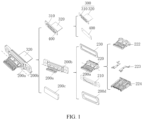
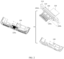
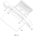
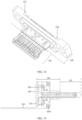
- the disclosed connector includes a housing 100, a socket tongue 200a, a socket base 200b, and a circuit board 300.
- the housing 100 is a foundation for mounting various components of the connector.
- the housing 100 is provided with an accommodating space 110 and an insertion hole 120 in communication with the accommodating space 110; the insertion hole 120 runs through a first end surface and a second end surface of the housing 100; the first end surface is opposite the second end surface; and the accommodating space 110 is arranged close to the second end surface.
- the first end surface may be an end into which an external plug extends when the external plug is in insertion fit with the connector.
- a first end portion of the socket tongue 200a extends into the insertion hole 120 in a suspending manner.
- the external plug can enter through an opening of the insertion hole 120 located on the first end surface to be electrically connected to the socket tongue 200a.
- the socket base 200b is connected to a second end portion of the socket tongue 200a, and the socket base 200b is at least partially located in the accommodating space 110.
- the socket base 200b seals an opening, located on the second end surface, of the insertion hole 120, and the socket base 200b has a first electrical connection portion arranged facing away from the socket tongue 200a.
- the circuit board 300 is disposed in the accommodating space 110, and the circuit board 300 includes an electrical connection sub-board 310.
- the electrical connection sub-board 310 is provided with a second electrical connection portion.
- a surface of the electrical connection sub-board 310 provided with the second electrical connection portion is opposite the second end surface.
- the surface of the electrical connection sub-board 310 provided with the second electrical connection portion may be parallel to the second end surface.
- an included angle may be formed between the surface of the electrical connection sub-board 310 provided with the second electrical connection portion and the second end surface, where the included angle is a small angle, for example, being less than 10 degrees or less than 5 degrees.
- the socket base 200b is located between the housing 100 and the electrical connection sub-board 310.
- the first electrical connection portion is electrically connected to the second electrical connection portion.
- the socket tongue 200a and the socket base 200b may be electrically connected to the circuit board 300 through the first electrical connection portion and the second electrical connection portion.
- the connector disclosed in this embodiment of this application is configured to be a structure including the housing 100, the socket tongue 200a, the socket base 200b, and the circuit board, so that the housing 100 may be provided with the accommodating space 110 and the insertion hole 120 in communication with the accommodating space 110.
- the insertion hole 120 can run through the first end surface and second end surface of the housing 100, so that the socket base 200b can seal the opening of the insertion hole 120 located on the second end surface, thereby preventing external dirt such as dust from entering the accommodating space 110 and protecting components in the accommodating space 110.
- the socket base 200b is provided with the first electrical connection portion arranged facing away from the socket tongue 200a.
- the electrical connection sub-board 310 is provided with the surface opposite the second end surface, so that the second electrical connection portion may be disposed on the surface of the electrical connection sub-board 310 opposite the second end surface.
- this ensures the area of the surface required for provision of the second electrical connection portion in a case of ensuring the electrical connection stability between the first electrical connection portion and the second electrical connection portion, thereby ensuring the electrical connection stability between the first electrical connection portion and the second electrical connection portion without increasing the length of the socket base 200b extending toward the circuit board 300.
- the first electrical connection portion and the second electrical connection portion are electrically connected to each other, so the first electrical connection portion and the second electrical connection portion need to be sealed for waterproofness.
- the electrical connection sub-board 310 and the socket base 200b can enclose the accommodating space 110.
- the accommodating space 110 can be used for filling of a sealing adhesive 200c.
- the first electrical connection portion and the second electrical connection portion may be located in the accommodating space 110.
- An electrical connection position between the first electrical connection portion and the second electrical connection portion is located in the accommodating space 110.
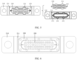
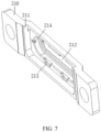
- the socket base 200b is configured to be a structure including the base fixing portion 210 and the base main body 220, so that the base fixing portion 210 may be provided with the first groove 211, thereby allowing the surface of the base fixing portion 210 where the first groove 211 is formed and the electrical connection sub-board 310 to enclose the accommodating space 110.
- the base fixing portion 210 is provided for forming the first groove 211 so as to enclose the accommodating space 110 with the electrical connection sub-board 310, thereby avoiding reduction in the strength of a component such as the housing 100 or the circuit board 300 due to the provision of a groove on the component such as the housing 100 or the circuit board 300 for enclosing the accommodating space 110.
- an edge of the base fixing portion 210 enclosing the first avoidance hole 212 may be provided with a second groove 213.
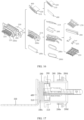
- the base main body 220 may include a first protrusion 221.
- the first protrusion 221 may be in location fit with the second groove 213 in a circumferential direction of the first avoidance hole 212.
- the edge of the base fixing portion 210 enclosing the first avoidance hole 212 may be provided with a third groove 214.
- the base main body 220 may include a base body 222 and a terminal partition plate 223 partially disposed in the base body 222.
- the terminal partition plate 223 can provide effects such as shielding magnetic fields and electric fields for the base body 222 and a terminal strip 224 on the base body 222.
- a portion of the terminal partition plate 223 protruding from the base body 222 may be located in the third groove 214.
- the portion of the terminal partition plate 223 protruding from the base body 222 may be in location fit with the third groove 214 in the circumferential direction of the first avoidance hole 212.
- the base body 222 may be a plastic component and may be formed by injection molding.
- the socket base 200b may further include a metal connection plate 230.
- the base fixing portion 210 may be a metal component.
- the metal connection plate 230 may be connected to the base fixing portion 210 through welding, and the metal connection plate 230 may be connected to the terminal partition plate 223 through welding.
- the base main body 220 may be in limiting fit with the metal connection plate 230 in the direction of the opening of the first groove 211. Specifically, at least a portion of the terminal partition plate 223 and at least a portion of the first protrusion 221 can be clamped between the base fixing portion 210 and the metal connection plate 230.
- the metal connection plate 230 is welded to the base fixing portion 210 and the terminal partition plate 223, so that the base main body 220 is in limiting fit with the base fixing portion 210 in the direction of the opening of the first groove 211, thereby improving the connection stability between the base main body 220 and the base fixing portion 210.
- a side wall of the first groove 211 is provided with an adhesive injection port 290 in communication with the first groove 211, and the adhesive injection port 290 may be in communication with the accommodating space 110.
- the first groove 211 of the base fixing portion 210 is provided with the adhesive injection port 290, helping to fill the sealing adhesive 200c into the accommodating space 110, and avoiding the provision of the adhesive injection port 290 in the housing 100 or the circuit board 300, thereby allowing for high strength of the housing 100 or the circuit board 300.
- an embodiment of this application discloses a connector, where the disclosed connector may be a Micro USB connector, a USB Type C connector, a Lightning connector, or the like.
- the disclosed connector includes a housing 100, a socket tongue 200a, a socket base 200b, and a circuit board 300.
- the housing 100 is a foundation for mounting various components of the connector.
- the housing 100 is provided with an accommodating space 110 and an insertion hole 120 in communication with the accommodating space 110; the insertion hole 120 runs through a first end surface and a second end surface of the housing 100; the first end surface is opposite the second end surface; and the accommodating space 110 is arranged close to the second end surface.
- the first end surface may be an end into which an external plug extends when the external plug is in insertion fit with the connector.
- a first end portion of the socket tongue 200a extends into the insertion hole 120 in a suspending manner.
- the external plug can enter through an opening of the insertion hole 120 located on the first end surface to be electrically connected to the socket tongue 200a.
- the socket base 200b is connected to a second end portion of the socket tongue 200a, and the socket base 200b is at least partially located in the accommodating space 110.
- the socket base 200b seals an opening, located on the second end surface, of the insertion hole 120, and the socket base 200b has a first electrical connection portion arranged facing away from the socket tongue 200a.
- the circuit board 300 is disposed in the accommodating space 110, and the circuit board 300 includes an electrical connection sub-board 310.
- the electrical connection sub-board 310 is provided with a second electrical connection portion.
- a surface of the electrical connection sub-board 310 provided with the second electrical connection portion is opposite the second end surface.
- the surface of the electrical connection sub-board 310 provided with the second electrical connection portion may be parallel to the second end surface.
- an included angle may be formed between the surface of the electrical connection sub-board 310 provided with the second electrical connection portion and the second end surface, where the included angle is a small angle, for example, being less than 10 degrees or less than 5 degrees.
- the socket base 200b is located between the housing 100 and the electrical connection sub-board 310.
- the first electrical connection portion is electrically connected to the second electrical connection portion.
- the socket tongue 200a and the socket base 200b may be electrically connected to the circuit board 300 through the first electrical connection portion and the second electrical connection portion.
- the connector disclosed in this embodiment of this application is configured to be a structure including the housing 100, the socket tongue 200a, the socket base 200b, and the circuit board, so that the housing 100 may be provided with the accommodating space 110 and the insertion hole 120 in communication with the accommodating space 110.
- the insertion hole 120 can run through the first end surface and second end surface of the housing 100, so that the socket base 200b can seal the opening of the insertion hole 120 located on the second end surface, thereby preventing external dirt such as dust from entering the accommodating space 110 and protecting components in the accommodating space 110.
- the socket base 200b is provided with the first electrical connection portion arranged facing away from the socket tongue 200a.
- the electrical connection sub-board 310 is provided with the surface opposite the second end surface, so that the second electrical connection portion may be disposed on the surface of the electrical connection sub-board 310 opposite the second end surface.
- this ensures the area of the surface required for provision of the second electrical connection portion in a case of ensuring the electrical connection stability between the first electrical connection portion and the second electrical connection portion, thereby ensuring the electrical connection stability between the first electrical connection portion and the second electrical connection portion without increasing the length of the socket base 200b extending toward the circuit board 300.
- the length of the socket base 200b extending toward the circuit board can be reduced, so that the space occupied by the connector can be reduced, thereby solving the problem in the related art that the length of the socket tongue extending toward the circuit board is increased to ensure the electrical connection stability between the socket tongue and the circuit board, which otherwise causes a large space occupied by a socket.
- the first electrical connection portion and the second electrical connection portion are electrically connected to each other, so the first electrical connection portion and the second electrical connection portion need to be sealed for waterproofness.
- the electrical connection sub-board 310 and the socket base 200b can enclose the accommodating space 110.
- the accommodating space 110 can be used for filling of a sealing adhesive 200c.
- the first electrical connection portion and the second electrical connection portion may be located in the accommodating space 110.
- An electrical connection position between the first electrical connection portion and the second electrical connection portion is located in the accommodating space 110.
- An adhesive injection port in communication with the accommodating space 110 may be formed between the electrical connection sub-board 310 and the socket base 200b, or the electrical connection sub-board 310 is provided with an adhesive injection port in communication with the accommodating space 110, or the socket base 200b is provided with an adhesive injection port in communication with the accommodating space 110.
- the positional relationship where the surface of the electrical connection sub-board 310 provided with the second electrical connection portion is opposite the second end surface allows the electrical connection sub-board 310 and the socket base 200b to enclose the accommodating space 110, so that the first electrical connection portion and the second electrical connection portion can be disposed in the accommodating space 110.
- this allows the accommodating space 110 to protect the first electrical connection portion and the second electrical connection portion and can provide a place for filling of the sealing adhesive 200c, thereby allowing the first electrical connection portion and the second electrical connection portion to be sealed by the sealing adhesive 200c after filling the sealing adhesive 200c into the accommodating space 110 through the adhesive injection port.
- the socket base 200b may include a first injection molding portion 240.
- the socket tongue 200a may include a second injection molding portion 201.
- the first injection molding portion 240 and the second injection molding portion 201 may form an integrated injection molding structure.
- the first injection molding portion 240 may be connected to the housing 100, and the first injection molding portion 240 may be provided with a fourth groove 241.
- An opening of the fourth groove 241 and the socket tongue 200a are respectively located on two sides of the socket base 200b facing away from each other.
- the first electrical connection portion is disposed on the first injection molding portion 240 and located in the fourth groove 241.
- the surface of the electrical connection sub-board 310 provided with the second electrical connection portion can cover the opening of the fourth groove 241.
- the second electrical connection portion may be located in the fourth groove 241.
- a surface of the first injection molding portion 240 where the fourth groove 241 is formed may be a second surface.
- the electrical connection sub-board 310 and the second surface can enclose the accommodating space 110.
- the first injection molding portion 240 or the electrical connection sub-board 310 may be provided with the adhesive injection port 290 in communication with the accommodating space 110.
- the circuit board 300 is disposed in the accommodating space 110, and the circuit board 300 includes an electrical connection sub-board 310.
- the electrical connection sub-board 310 is provided with a second electrical connection portion.
- a surface of the electrical connection sub-board 310 provided with the second electrical connection portion is opposite the second end surface.
- the surface of the electrical connection sub-board 310 provided with the second electrical connection portion may be parallel to the second end surface.
- an included angle may be formed between the surface of the electrical connection sub-board 310 provided with the second electrical connection portion and the second end surface, where the included angle is a small angle, for example, being less than 10 degrees or less than 5 degrees.
- the socket base 200b is located between the housing 100 and the electrical connection sub-board 310.
- the first electrical connection portion is electrically connected to the second electrical connection portion.
- the socket tongue 200a and the socket base 200b may be electrically connected to the circuit board 300 through the first electrical connection portion and the second electrical connection portion.
- the connector disclosed in this embodiment of this application is configured to be a structure including the housing 100, the socket tongue 200a, the socket base 200b, and the circuit board, so that the housing 100 may be provided with the accommodating space 110 and the insertion hole 120 in communication with the accommodating space 110.
- the insertion hole 120 can run through the first end surface and second end surface of the housing 100, so that the socket base 200b can seal the opening of the insertion hole 120 located on the second end surface, thereby preventing external dirt such as dust from entering the accommodating space 110 and protecting components in the accommodating space 110.
- the socket base 200b is provided with the first electrical connection portion arranged facing away from the socket tongue 200a.
- the electrical connection sub-board 310 is provided with the surface opposite the second end surface, so that the second electrical connection portion may be disposed on the surface of the electrical connection sub-board 310 opposite the second end surface.
- this ensures the area of the surface required for provision of the second electrical connection portion in a case of ensuring the electrical connection stability between the first electrical connection portion and the second electrical connection portion, thereby ensuring the electrical connection stability between the first electrical connection portion and the second electrical connection portion without increasing the length of the socket base 200b extending toward the circuit board 300.
- the length of the socket base 200b extending toward the circuit board can be reduced, so that the space occupied by the connector can be reduced, thereby solving the problem in the related art that the length of the socket tongue extending toward the circuit board is increased to ensure the electrical connection stability between the socket tongue and the circuit board, which otherwise causes a large space occupied by a socket.
- the first electrical connection portion and the second electrical connection portion are electrically connected to each other, so the first electrical connection portion and the second electrical connection portion need to be sealed for waterproofness.
- the electrical connection sub-board 310 and the socket base 200b can enclose the accommodating space 110.
- the accommodating space 110 can be used for filling of a sealing adhesive 200c.
- the first electrical connection portion and the second electrical connection portion may be located in the accommodating space 110.
- An electrical connection position between the first electrical connection portion and the second electrical connection portion is located in the accommodating space 110.
- An adhesive injection port in communication with the accommodating space 110 may be formed between the electrical connection sub-board 310 and the socket base 200b, or the electrical connection sub-board 310 is provided with an adhesive injection port in communication with the accommodating space 110, or the socket base 200b is provided with an adhesive injection port in communication with the accommodating space 110.
- the positional relationship where the surface of the electrical connection sub-board 310 provided with the second electrical connection portion is opposite the second end surface allows the electrical connection sub-board 310 and the socket base 200b to enclose the accommodating space 110, so that the first electrical connection portion and the second electrical connection portion can be disposed in the accommodating space 110.
- this allows the accommodating space 110 to protect the first electrical connection portion and the second electrical connection portion and can provide a place for filling of the sealing adhesive 200c, thereby allowing the first electrical connection portion and the second electrical connection portion to be sealed by the sealing adhesive 200c after filling the sealing adhesive 200c into the accommodating space 110 through the adhesive injection port.
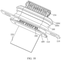
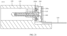
- the socket base 200b may include a cylindrical reinforcing member 260 and a third injection molding portion 270.
- the third injection molding portion 270 may be at least partially disposed in the cylindrical reinforcing member 260.
- the cylindrical reinforcing member 260 may be provided with an avoidance notch.
- the third injection molding portion 270 may be provided with a fifth groove. An opening of the fifth groove and the socket tongue 200a may be located on two sides of the socket base 200b facing away from each other.
- the first electrical connection portion may be disposed on the third injection molding portion 270 and located in the fifth groove.
- the surface of the electrical connection sub-board 310 provided with the second electrical connection portion can cover the opening of the fifth groove.
- the second electrical connection portion may be located in the fifth groove.
- a surface of the third injection molding portion 270 where the fifth groove is formed may be a third surface.
- the electrical connection sub-board 310 and the third surface can enclose the accommodating space 110.
- the electrical connection sub-board 310 and the avoidance notch can enclose the adhesive injection port 290.
- the adhesive injection port 290 may be in communication with the accommodating space.
- the socket base 200b is configured to include the cylindrical reinforcing member 260 and the third injection molding portion 270, so that the third injection molding portion 270 may be at least partially disposed in the cylindrical reinforcing member 260.
- the cylindrical reinforcing member 260 can protect the third injection molding portion 270 and can reinforce the overall socket base 200b.
- the third injection molding portion 270 is provided with the fifth groove, so that the first electrical connection portion and the second electrical connection portion may be disposed in the fifth groove.
- the electrical connection sub-board 310 and the third surface being the surface of the third injection molding portion 270 where the fifth groove is formed can enclose the accommodating space 110, so that the first electrical connection portion and the second electrical connection portion may be disposed in the accommodating space 110, thereby sealing the first electrical connection portion and the second electrical connection portion after filling the sealing adhesive 200 through the adhesive injection port 290 enclosed by the electrical connection sub-board 310 and the avoidance notch.
- the cylindrical reinforcing member 260 may be a metal structural member.
- the socket base 200b may further include a metal connection member 280, where the metal connection member 280 may be connected to the third injection molding portion 270 through injection molding, and the metal connection member 280 may be connected to the cylindrical reinforcing member 260 through welding.
Landscapes
- Engineering & Computer Science (AREA)
- Signal Processing (AREA)
- Connector Housings Or Holding Contact Members (AREA)
Applications Claiming Priority (2)
| Application Number | Priority Date | Filing Date | Title |
|---|---|---|---|
| CN202211178600.8A CN115473072B (zh) | 2022-09-26 | 2022-09-26 | 连接器及电子设备 |
| PCT/CN2023/121165 WO2024067504A1 (zh) | 2022-09-26 | 2023-09-25 | 连接器及电子设备 |
Publications (2)
| Publication Number | Publication Date |
|---|---|
| EP4576444A1 true EP4576444A1 (de) | 2025-06-25 |
| EP4576444A4 EP4576444A4 (de) | 2025-11-05 |
Family
ID=84335266
Family Applications (1)
| Application Number | Title | Priority Date | Filing Date |
|---|---|---|---|
| EP23870734.3A Pending EP4576444A4 (de) | 2022-09-26 | 2023-09-25 | Verbinder und elektronische vorrichtung |
Country Status (4)
| Country | Link |
|---|---|
| US (1) | US20250219335A1 (de) |
| EP (1) | EP4576444A4 (de) |
| CN (1) | CN115473072B (de) |
| WO (1) | WO2024067504A1 (de) |
Families Citing this family (3)
| Publication number | Priority date | Publication date | Assignee | Title |
|---|---|---|---|---|
| CN115473072B (zh) * | 2022-09-26 | 2026-03-17 | 维沃移动通信有限公司 | 连接器及电子设备 |
| CN116247463A (zh) * | 2023-03-23 | 2023-06-09 | 维沃移动通信有限公司 | 连接器和电子设备 |
| CN116667040B (zh) * | 2023-06-21 | 2025-12-30 | 维沃移动通信有限公司 | 连接器及电子设备 |
Family Cites Families (16)
| Publication number | Priority date | Publication date | Assignee | Title |
|---|---|---|---|---|
| TW540880U (en) * | 2001-12-26 | 2003-07-01 | Hon Hai Prec Ind Co Ltd | Electrical connector |
| TWI466401B (zh) * | 2011-06-17 | 2014-12-21 | Molex Inc | A plug device, a socket device, and combinations thereof |
| TWM501018U (zh) * | 2014-12-04 | 2015-05-11 | Lotes Co Ltd | 電連接器 |
| CN104733950B (zh) * | 2015-03-09 | 2024-03-29 | 连展科技(深圳)有限公司 | 防水型插座电连接器 |
| CN106571556B (zh) * | 2015-10-12 | 2019-04-26 | 富士康(昆山)电脑接插件有限公司 | 电连接器及其制造方法 |
| US11114790B2 (en) * | 2016-08-12 | 2021-09-07 | Chou Hsien Tsai | Reversible dual-position electric connector |
| CN206742538U (zh) * | 2017-05-22 | 2017-12-12 | 上海莫仕连接器有限公司 | 电连接器 |
| US9997866B1 (en) * | 2017-11-24 | 2018-06-12 | Cheng Uei Precision Industry Co., Ltd. | Waterproof connector |
| CN109038000B (zh) * | 2018-08-13 | 2020-09-25 | 昆山杰顺通精密组件有限公司 | 正反插usb插座 |
| CN209056690U (zh) * | 2018-09-30 | 2019-07-02 | 苏州华旃航天电器有限公司 | 一种密封型转接器 |
| CN209233042U (zh) * | 2018-12-18 | 2019-08-09 | 江西联创宏声电子股份有限公司 | Usb插座及电子产品 |
| CN211556202U (zh) * | 2020-03-27 | 2020-09-22 | 维沃移动通信有限公司 | 连接器插座以及电子设备 |
| TWM618327U (zh) * | 2020-12-15 | 2021-10-11 | 大陸商東莞立德精密工業有限公司 | 一種充電轉接裝置 |
| CN113518524B (zh) * | 2021-04-19 | 2022-12-13 | 维沃移动通信有限公司 | 电子设备 |
| CN215645216U (zh) * | 2021-08-30 | 2022-01-25 | 安费诺电子装配(厦门)有限公司 | 一种线缆连接器及连接器组件 |
| CN115473072B (zh) * | 2022-09-26 | 2026-03-17 | 维沃移动通信有限公司 | 连接器及电子设备 |
-
2022
- 2022-09-26 CN CN202211178600.8A patent/CN115473072B/zh active Active
-
2023
- 2023-09-25 WO PCT/CN2023/121165 patent/WO2024067504A1/zh not_active Ceased
- 2023-09-25 EP EP23870734.3A patent/EP4576444A4/de active Pending
-
2025
- 2025-03-17 US US19/082,138 patent/US20250219335A1/en active Pending
Also Published As
| Publication number | Publication date |
|---|---|
| EP4576444A4 (de) | 2025-11-05 |
| CN115473072A (zh) | 2022-12-13 |
| US20250219335A1 (en) | 2025-07-03 |
| CN115473072B (zh) | 2026-03-17 |
| WO2024067504A1 (zh) | 2024-04-04 |
Similar Documents
| Publication | Publication Date | Title |
|---|---|---|
| EP4576444A1 (de) | Verbinder und elektronische vorrichtung | |
| US6227872B1 (en) | Moisture resistant electrical connector for a cellular telephone | |
| US9401568B1 (en) | Connecting device and electronic device | |
| KR20150027096A (ko) | 전기 커넥터 | |
| JP3817489B2 (ja) | リセプタクル電気コネクタ | |
| WO2022268017A1 (zh) | 电子设备 | |
| JP4916388B2 (ja) | 携帯用電子機器 | |
| CN111916483B (zh) | 一种显示屏体组件 | |
| EP4138527B1 (de) | Endgerätevorrichtung | |
| CN218849684U (zh) | 终端设备 | |
| JP2013106196A (ja) | 携帯端末 | |
| CN111082248B (zh) | 一种移动终端 | |
| CN215497298U (zh) | Usb插座和电子设备 | |
| CN215989386U (zh) | 电连接器 | |
| CN220585654U (zh) | Usb连接头 | |
| CN221410431U (zh) | 一种气溶胶生成装置及其电池仓结构 | |
| CN222507879U (zh) | 电池与电池盖一体化组件及手机 | |
| CN216624683U (zh) | Usb座安装结构 | |
| CN223942159U (zh) | 一种电源适配器 | |
| CN212934995U (zh) | 防尘型usb连接器 | |
| CN116470334A (zh) | 电连接器和电子设备 | |
| CN220605132U (zh) | 连接器 | |
| CN214490645U (zh) | 机器人关节结构及机器人 | |
| CN216598043U (zh) | 接口部件、连接器组件、印刷电路板组件和电池组件 | |
| CN214313691U (zh) | 电连接器 |
Legal Events
| Date | Code | Title | Description |
|---|---|---|---|
| STAA | Information on the status of an ep patent application or granted ep patent |
Free format text: STATUS: THE INTERNATIONAL PUBLICATION HAS BEEN MADE |
|
| PUAI | Public reference made under article 153(3) epc to a published international application that has entered the european phase |
Free format text: ORIGINAL CODE: 0009012 |
|
| STAA | Information on the status of an ep patent application or granted ep patent |
Free format text: STATUS: REQUEST FOR EXAMINATION WAS MADE |
|
| 17P | Request for examination filed |
Effective date: 20250319 |
|
| AK | Designated contracting states |
Kind code of ref document: A1 Designated state(s): AL AT BE BG CH CY CZ DE DK EE ES FI FR GB GR HR HU IE IS IT LI LT LU LV MC ME MK MT NL NO PL PT RO RS SE SI SK SM TR |
|
| A4 | Supplementary search report drawn up and despatched |
Effective date: 20251009 |
|
| RIC1 | Information provided on ipc code assigned before grant |
Ipc: H01R 13/46 20060101AFI20251002BHEP Ipc: H01R 13/52 20060101ALI20251002BHEP Ipc: H04M 1/02 20060101ALI20251002BHEP Ipc: H01R 13/74 20060101ALI20251002BHEP Ipc: H01R 24/60 20110101ALI20251002BHEP Ipc: H04M 1/18 20060101ALI20251002BHEP |
|
| DAV | Request for validation of the european patent (deleted) | ||
| DAX | Request for extension of the european patent (deleted) | ||
| STAA | Information on the status of an ep patent application or granted ep patent |
Free format text: STATUS: EXAMINATION IS IN PROGRESS |