EP4138531A1 - Wechselrichtervorrichtung von mobilität - Google Patents
Wechselrichtervorrichtung von mobilität Download PDFInfo
- Publication number
- EP4138531A1 EP4138531A1 EP22172501.3A EP22172501A EP4138531A1 EP 4138531 A1 EP4138531 A1 EP 4138531A1 EP 22172501 A EP22172501 A EP 22172501A EP 4138531 A1 EP4138531 A1 EP 4138531A1
- Authority
- EP
- European Patent Office
- Prior art keywords
- cooler
- power module
- inverter apparatus
- housing
- space
- Prior art date
- Legal status (The legal status is an assumption and is not a legal conclusion. Google has not performed a legal analysis and makes no representation as to the accuracy of the status listed.)
- Pending
Links
Images


Classifications
-
- H—ELECTRICITY
- H05—ELECTRIC TECHNIQUES NOT OTHERWISE PROVIDED FOR
- H05K—PRINTED CIRCUITS; CASINGS OR CONSTRUCTIONAL DETAILS OF ELECTRIC APPARATUS; MANUFACTURE OF ASSEMBLAGES OF ELECTRICAL COMPONENTS
- H05K7/00—Constructional details common to different types of electric apparatus
- H05K7/20—Modifications to facilitate cooling, ventilating, or heating
- H05K7/2089—Modifications to facilitate cooling, ventilating, or heating for power electronics, e.g. for inverters for controlling motor
- H05K7/209—Heat transfer by conduction from internal heat source to heat radiating structure
-
- H—ELECTRICITY
- H05—ELECTRIC TECHNIQUES NOT OTHERWISE PROVIDED FOR
- H05K—PRINTED CIRCUITS; CASINGS OR CONSTRUCTIONAL DETAILS OF ELECTRIC APPARATUS; MANUFACTURE OF ASSEMBLAGES OF ELECTRICAL COMPONENTS
- H05K7/00—Constructional details common to different types of electric apparatus
- H05K7/20—Modifications to facilitate cooling, ventilating, or heating
- H05K7/2089—Modifications to facilitate cooling, ventilating, or heating for power electronics, e.g. for inverters for controlling motor
- H05K7/20927—Liquid coolant without phase change
-
- H—ELECTRICITY
- H05—ELECTRIC TECHNIQUES NOT OTHERWISE PROVIDED FOR
- H05K—PRINTED CIRCUITS; CASINGS OR CONSTRUCTIONAL DETAILS OF ELECTRIC APPARATUS; MANUFACTURE OF ASSEMBLAGES OF ELECTRICAL COMPONENTS
- H05K7/00—Constructional details common to different types of electric apparatus
- H05K7/20—Modifications to facilitate cooling, ventilating, or heating
- H05K7/2029—Modifications to facilitate cooling, ventilating, or heating using a liquid coolant with phase change in electronic enclosures
- H05K7/20318—Condensers
-
- H—ELECTRICITY
- H02—GENERATION; CONVERSION OR DISTRIBUTION OF ELECTRIC POWER
- H02M—APPARATUS FOR CONVERSION BETWEEN AC AND AC, BETWEEN AC AND DC, OR BETWEEN DC AND DC, AND FOR USE WITH MAINS OR SIMILAR POWER SUPPLY SYSTEMS; CONVERSION OF DC OR AC INPUT POWER INTO SURGE OUTPUT POWER; CONTROL OR REGULATION THEREOF
- H02M7/00—Conversion of AC power input into DC power output; Conversion of DC power input into AC power output
- H02M7/003—Constructional details, e.g. physical layout, assembly, wiring or busbar connections
-
- H—ELECTRICITY
- H05—ELECTRIC TECHNIQUES NOT OTHERWISE PROVIDED FOR
- H05K—PRINTED CIRCUITS; CASINGS OR CONSTRUCTIONAL DETAILS OF ELECTRIC APPARATUS; MANUFACTURE OF ASSEMBLAGES OF ELECTRICAL COMPONENTS
- H05K7/00—Constructional details common to different types of electric apparatus
- H05K7/20—Modifications to facilitate cooling, ventilating, or heating
- H05K7/2039—Modifications to facilitate cooling, ventilating, or heating characterised by the heat transfer by conduction from the heat generating element to a dissipating body
- H05K7/20436—Inner thermal coupling elements in heat dissipating housings, e.g. protrusions or depressions integrally formed in the housing
Definitions
- the present disclosure relates to an inverter apparatus of a mobility, the inverter apparatus having a structure in which a power module and a cooler are stacked so that an overall size of the inverter apparatus is reduced, and the cooler is pressed by a cover so that the cooler and the power module are in contact with each other, increasing the cooling performance of the cooler.
- An environmentally friendly vehicle such as a hybrid vehicle or an electric vehicle, which utilizes an electric motor as a drive source, generally utilizes a high-voltage battery as an energy source for driving the electric motor. Furthermore, as a power conversion component, the environmentally friendly vehicle utilizes an inverter that provides power supply to the electric motor and utilizes a low DC-DC converter (LDC) that generates 12V power for a vehicle.
- LDC low DC-DC converter
- the inverter converts a DC power supply of the high-voltage battery into a three phase AC power supply, and provides the three phase AC power supply to the electric motor.
- a main objective of a conventional electric vehicle is to drive in a short-distance and to drive in a city, so that an electric vehicle having a relatively predetermined output model of about 100 kW has been used to be a mainstream conventional electric vehicle. That is, because the electric vehicle does not need a predetermined output, a single motor which is a power source of the electric vehicle was generally used at front wheels, and thus the inverter that supplies current to the motor was also provided to correspond to an output within a relatively small range.
- the inverter provided in a plane, a power module, a capacitor, and an LDC are disposed on a bottom surface of a housing, and a control board is provided to be positioned at a top end portion of the housing.
- the inverter had a structure in which the power module, the capacitor, and the LDC are simply stacked inside the housing, so that there has been a problem that an overall size of the inverter is increased.
- a cooling flow path through which a cooling water flows has been formed below the power module in which an excessive heat occurs and the LDC, so that performance deterioration and damage of an element caused by excessive heat is prevented.
- a performance of transferring heat between the cooling flow path and the power module was not secured, so that there is a problem that cooling of the power module is not smoothly performed.
- Various aspects of the present disclosure are directed to providing an inverter apparatus of a mobility, the inverter apparatus including a structure in which a power module and a cooler are stacked so that an overall size of the inverter apparatus is reduced, and the cooler is pressed by a cover so that the cooler and the power module are in contact with each other, increasing the cooling performance of the cooler.
- an inverter apparatus of a mobility including: a housing provided with an internal space therein; a power module provided in the internal space of the housing; a cooler provided to be in contact with the power module and configured to cool the power module by a heat transfer with the power module; and a cover mounted on the housing and configured to shield the internal space, the cover being configured to press the cooler by being in contact with the cooler when the cover is mounted on the housing, bringing the cooler into close contact with the power module.
- the cooler may include a plurality of coolers which is an upper end cooler and a lower end cooler, and the power module may be located between the upper end cooler and the lower end cooler.
- the inverter apparatus may further include: a control board electrically connected to the power module in the internal space of the housing, wherein the control board may be disposed lateral to the power module or the cooler in the internal space.
- a plurality of coolers may be provided to correspond to the power modules, respectively, and the power modules and the coolers may be disposed to be spaced out along a border of the control board.
- the housing may be divided into an upper space and a lower space separated by a partition wall that crosses the internal space, and the power module and the cooler may be provided in the upper space and a bus bar module and a capacitor that are electrically connected to the power module may be provided in the lower space.
- the bus bar modules may be disposed to be spaced out along a border of the capacitor.
- the housing may be configured so that an upper portion and a lower portion thereof are opened, so that the upper space may be opened upward and the lower space may be opened downward.
- a portion of the cover matching the cooler may protrude downward, forming a recessed portion which is in contact with the cooler.
- the recessed portion may be formed by the cover being recessed downward, and the recessed portion may be formed to be divided into a plurality of recessed portions in a longitudinal direction of the cooler.
- the inverter apparatus of the mobility configured as described above has the structure in which the power module and the cooler are stacked so that an overall size of the inverter apparatus is reduced, and the cooler is pressed by the cover so that the cooler and the power module are in contact with each other, so that the cooling performance of the cooler is increased.
- FIG. 1 is a view exemplarily illustrating an inverter apparatus of a mobility according to an exemplary embodiment of the present disclosure.
- FIG. 2 is a view exemplarily illustrating an internal portion of a housing of the inverter apparatus of the mobility according to an exemplary embodiment of the present disclosure.
- FIG. 3 is an assembly view exemplarily illustrating the inverter apparatus of the mobility according to an exemplary embodiment of the present disclosure.
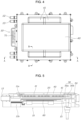
- FIG. 4 is a plan view exemplarily illustrating the inverter apparatus of the mobility according to an exemplary embodiment of the present disclosure.
- FIG. 5 is a cross-sectional view taken along line A-A in FIG. 4 .
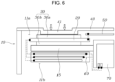
- FIG. 6 is a cross-sectional view taken along line B-B in FIG. 4 .
- the inverter apparatus of the mobility includes: a housing 10 provided with an internal space 11; a power module 20 provided in the internal space 11 of the housing 10; a cooler 30 provided to be in contact with the power module 20 and configured to cool the power module 20 by a heat transfer with the power module 20; and a cover 40 mounted on the housing 10 and configured to shield the internal space 11, the cover 40 being configured to press the cooler 30 by being in contact with the cooler 30 when the cover 40 is mounted on the housing 10, bringing the cooler 30 into close contact with the power module 20.
- the internal space 11 in which various electrical components that form the inverter including the power module 20 and the cooler 30 are provided is formed in the housing 10.
- the housing 10 is formed so that either an upper portion or a lower portion thereof is opened or both the upper portion and the lower portion thereof are opened, so that the various electrical components including the power module 20 and the cooler 30 may be mounted in the internal space 11.
- the cover 40 is mounted on the housing 10 and the cover 40 shields the internal space 11, a foreign substance is blocked from being introduced into the internal space 11 of the housing 10, and internal components are protected from external shock.
- an inlet port 12 and an outlet port 13 into which a cooling medium is introduced and discharged are formed, and a terminal insertion portion 14 where a terminal 71 of a capacitor that will be described later is exposed may be formed.
- the power module 20 and the cooler 30 are provided in the internal space 11 of the housing 10.
- the power module 20 is configured to convert direct current (DC) into three-phase alternating current (AC), and high-temperature heat is generated due to operating characteristics of the power module 20.
- the cooler 30 for cooling the power module 20 is provided in the housing 10 and is disposed to be in contact with the power module 20, and the cooling medium undergoes heat transfer with the power module 20 so that the power module 20 is cooled.
- the cover 40 is mounted on the housing 10 and shields the internal space 11, and is configured to press the cooler 30 by being in contact with the cooler 30 when the cover 40 is mounted on the housing 10, so that the cooler 30 is in close contact with the power module 20.
- the cooler 30 and the power module 20 are in contact with each other, a heat transferring performance is secured, so that a performance of cooling the power module 20 is increased. Furthermore, as a vibration transferred from outside to the housing 10 is transferred to the cooler 30 through the cover 40, the cooling medium circulating through the cooler 30 absorbs the vibration, so that a problem of a resonance frequency of the cover 40 is solved. Furthermore, when the vibration transferred through the cover 40 is transferred to the cooler 30, a vortex is generated in the cooling medium inside the cooler 30, so that a greater cooling performance may be further secured.
- the cooler 30 includes a plurality of components which is an upper end cooler 30a and a lower end cooler 30b, and the power module 20 is located between the upper end cooler 30a and the lower end cooler 30b.
- the cooler 30 includes the upper end cooler 30a which is disposed at an upper side of the power module 20 and the lower end cooler 30b which is disposed at a lower side of the power module 20. Furthermore, because the power module 20 is located between the upper end cooler 30a and the lower end cooler 30b, the power module 20 undergoes heat transfer with each of the upper end cooler 30a and the lower end cooler 30b, so that the cooling may be efficiently performed.
- These upper end cooler 30a and the lower end cooler 30b extend in a longitudinal direction of the power module 20, allowing the overall portion of the power module 20 to be cooled. That is, the power module 20 and each of the upper end cooler 30a and the lower end cooler 30b are formed so that contact areas between each other are secured as much as possible, so that the performance of cooling the power module 20 may be increased.
- a control board 50 which is electrically connected to the power module 20 is further provided. Furthermore, in the internal space 11, the control board 50 is disposed lateral to the power module 20 or the cooler 30.
- the control board 50 for controlling the power module 20 is provided.
- the control board 50 is disposed lateral to the power module 20 or the cooler 30, a vertical height of the housing 10 in accordance with the provision of the control board 50 is reduced.
- control board 50 may be disposed lateral to the cooler 30 to avoid damage caused by heat when heat is generated on the power module 20.
- the control board 50 is disposed lateral to the cooler 30 and is spaced apart in a vertical direction from the cooler 30, so that influences of both the power module 20 and the cooler 30 are minimized.
- a plurality of coolers 30 is provided to correspond to the power modules 20, respectively, and the power modules 20 and the coolers 30 may be disposed to be spaced out along a border of the control board 50.
- the plurality of coolers 30 is provided to correspond to the power modules 20, respectively. Accordingly, because the power modules 20 are cooled by the coolers 30, respectively, the performance of cooling the power module 20 by the cooler 30 may be secured even when the plurality of power modules 20 is provided.
- the vertical height of the housing 10 in accordance with the provision of the control board 50 is reduced. That is, because the height of the housing 10 is increased when the power module 20, the cooler 30, and the control board 50 are configured in a stacked structure, the power module 20 and the cooler 30 are disposed lateral to the control board 50, so that the height of the housing 10 is reduced, and thus the inverter of the present disclosure is configured for being easily applied to the mobility.
- the housing 10 includes an upper space 11a and a lower space 11b by a partition wall 15 that crosses the internal space 11. Furthermore, the power module 20 and the cooler 30 are provided in the upper space 11a, and a bus bar module 60 and a capacitor 70 that are electrically connected to the power module 20 are provided in the lower space 11b.
- each of the P and N terminals is connected to the power module 20 via the bus bar module 60.
- the internal space 11 includes the upper space 11a and the lower space 11b by the partition wall 15.
- the power module 20, the cooler 30, and the control board 50 are provided in the upper space 11a
- the bus bar module 60 and the capacitor 70 that are electrically connected to the power module 20 are provided in the lower space 11b.
- the power module 20, the cooler 30, and the control board 50 are mounted at the upper space 11a via the housing 10 and the partition wall 15, and at the lower space 11b, the bus bar module 60 and the capacitor 70 are mounted at the housing 10 and the partition wall 15, so that packaging of each configuration is facilitated and interference between the configurations is minimized.
- the bus bar module 60 and the capacitor 70 are separated from the internal space 11 of the housing 10 by the partition wall 15, so that influence of electromagnetic waves is reduced.
- the bus bar modules 60 are disposed to be spaced out along a border of the capacitor 70.
- the vertical height of the housing 10 in accordance with the provision of the bus bar module 60 and the capacitor 70 that are provided inside the housing 10 is reduced. That is, because the height of the housing 10 is increased when the bus bar module 60 and the capacitor 70 are configured in a stacked structure, the bus bar module 60 is disposed lateral to the capacitor 70, so that the height of the housing 10 is reduced.
- the housing 10 is formed so that the upper and lower portions thereof are opened, so that the upper space 11a is opened upward and the lower space 11b is opened downward.
- parts of electrical components such as the power module 20, the cooler 30, and the control board 50 may be mounted at the internal space 11 by being inserted into the opened upper portion of the housing 10, and parts of electrical components such as the bus bar module 60 and the capacitor 70 may be mounted at the internal space 11 by being inserted into the opened lower portion of the housing 10.
- the cover 40 is mounted on the upper portion of the housing 10 and shields the upper space 11a, and a separate cover 40 may be mounted on the lower portion of the housing 10 and may shield the lower space 11b.
- the recessed portion 41 that protrudes downward is formed at an internal side surface of the cover 40, the recessed portion 41 is in contact with the cooler 30 and presses the cooler 30 when the cover 40 is mounted on the housing 10, so that the cooler 30 is in close contact with the power module 20.
- the recessed portion 41 is formed by the cover 40 being recessed downward, and the recessed portion 41 may be formed to be divided into a plurality of recessed portions 41 in a longitudinal direction of the cooler 30.
- the recessed portion 41 is matched to the cooler 30 when the cover 40 is mounted on the housing 10, the cooler 30 pressed by the recessed portion 41 and the power module 20 are in close contact with each other, so that the performance of transferring heat between the cooler 30 and the power module 20 is secured.
- the vibration generated from the cover 40 is transferred to the cooler 30, and the vibration is absorbed by the cooling medium of the cooler 30.
- the vibration is transferred to the cooler 30 from the cover 40 through the recessed portion 41, the vortex is generated in the cooling medium which is circulating through the cooler 30, so that the cooling performance may be secured.
- the inverter apparatus has the structure in which the power module 20 and the cooler 30 are stacked so that an overall size of the inverter apparatus is reduced, and the cooler 30 is pressed by the cover 40 so that the cooling performance of the cooler 30 is increased.
Landscapes
- Engineering & Computer Science (AREA)
- Microelectronics & Electronic Packaging (AREA)
- Physics & Mathematics (AREA)
- Thermal Sciences (AREA)
- Power Engineering (AREA)
- Inverter Devices (AREA)
- Electric Propulsion And Braking For Vehicles (AREA)
Applications Claiming Priority (1)
| Application Number | Priority Date | Filing Date | Title |
|---|---|---|---|
| KR1020210109044A KR102952395B1 (ko) | 2021-08-18 | 2021-08-18 | 모빌리티의 인버터 장치 |
Publications (1)
| Publication Number | Publication Date |
|---|---|
| EP4138531A1 true EP4138531A1 (de) | 2023-02-22 |
Family
ID=81597915
Family Applications (1)
| Application Number | Title | Priority Date | Filing Date |
|---|---|---|---|
| EP22172501.3A Pending EP4138531A1 (de) | 2021-08-18 | 2022-05-10 | Wechselrichtervorrichtung von mobilität |
Country Status (4)
| Country | Link |
|---|---|
| US (1) | US12150285B2 (de) |
| EP (1) | EP4138531A1 (de) |
| KR (1) | KR102952395B1 (de) |
| CN (1) | CN115708304A (de) |
Families Citing this family (3)
| Publication number | Priority date | Publication date | Assignee | Title |
|---|---|---|---|---|
| KR102743632B1 (ko) * | 2023-04-03 | 2024-12-17 | 주식회사 효원파워텍 | 수소 전기차용 인버터 |
| KR102864452B1 (ko) * | 2024-01-03 | 2025-09-25 | 주식회사 현대케피코 | 전력 변환 장치 |
| KR102798204B1 (ko) * | 2024-03-29 | 2025-04-22 | 주식회사 현대케피코 | 전력변환장치 |
Citations (3)
| Publication number | Priority date | Publication date | Assignee | Title |
|---|---|---|---|---|
| JP2012227472A (ja) * | 2011-04-22 | 2012-11-15 | Mitsubishi Electric Corp | 電子部品の実装構造体 |
| US20160106011A1 (en) * | 2014-10-14 | 2016-04-14 | Denso Corporation | Electric power converter |
| KR20160109200A (ko) * | 2015-03-10 | 2016-09-21 | 한온시스템 주식회사 | 전기소자 쿨링모듈 |
Family Cites Families (11)
| Publication number | Priority date | Publication date | Assignee | Title |
|---|---|---|---|---|
| KR200157525Y1 (ko) | 1997-07-31 | 1999-09-15 | 이해규 | 보수성을 향상한 인버터구조 |
| US10321585B2 (en) * | 2008-07-29 | 2019-06-11 | Hitachi, Ltd. | Power conversion apparatus and electric vehicle |
| JP5407275B2 (ja) * | 2008-10-27 | 2014-02-05 | 株式会社デンソー | 電力変換装置 |
| US20130003301A1 (en) * | 2010-11-24 | 2013-01-03 | Toyota Jidosha Kabushiki Kaisha | Stacked cooler |
| JP5506749B2 (ja) * | 2011-07-25 | 2014-05-28 | 日立オートモティブシステムズ株式会社 | 電力変換装置 |
| JP5802629B2 (ja) * | 2012-08-31 | 2015-10-28 | 日立オートモティブシステムズ株式会社 | 電力変換装置 |
| JP5725067B2 (ja) * | 2013-03-25 | 2015-05-27 | 株式会社デンソー | 電力変換装置 |
| JP5991345B2 (ja) * | 2013-12-26 | 2016-09-14 | 株式会社デンソー | 電力変換装置 |
| DE112016000129B4 (de) * | 2015-03-10 | 2021-10-14 | Hanon Systems | Wärmetauscher zum Kühlen eines elektrischen Elements, sowie Wärmetauscheranordnung und Kühlmodul |
| US10136564B2 (en) * | 2016-09-30 | 2018-11-20 | Denso Corporation | Power converter |
| KR102458054B1 (ko) * | 2017-12-29 | 2022-10-25 | 한온시스템 주식회사 | 모터의 인버터 방열커버 |
-
2021
- 2021-08-18 KR KR1020210109044A patent/KR102952395B1/ko active Active
-
2022
- 2022-05-06 US US17/738,552 patent/US12150285B2/en active Active
- 2022-05-10 EP EP22172501.3A patent/EP4138531A1/de active Pending
- 2022-06-02 CN CN202210624284.6A patent/CN115708304A/zh active Pending
Patent Citations (3)
| Publication number | Priority date | Publication date | Assignee | Title |
|---|---|---|---|---|
| JP2012227472A (ja) * | 2011-04-22 | 2012-11-15 | Mitsubishi Electric Corp | 電子部品の実装構造体 |
| US20160106011A1 (en) * | 2014-10-14 | 2016-04-14 | Denso Corporation | Electric power converter |
| KR20160109200A (ko) * | 2015-03-10 | 2016-09-21 | 한온시스템 주식회사 | 전기소자 쿨링모듈 |
Also Published As
| Publication number | Publication date |
|---|---|
| KR20230026887A (ko) | 2023-02-27 |
| CN115708304A (zh) | 2023-02-21 |
| US20230055412A1 (en) | 2023-02-23 |
| US12150285B2 (en) | 2024-11-19 |
| KR102952395B1 (ko) | 2026-04-13 |
Similar Documents
| Publication | Publication Date | Title |
|---|---|---|
| EP4138531A1 (de) | Wechselrichtervorrichtung von mobilität | |
| EP2180776B1 (de) | Kraftfahrzeugwechselrichtereinheit | |
| EP2830073B1 (de) | Stromrichter | |
| CN101777849B (zh) | 电力变换装置 | |
| US9078376B2 (en) | Power conversion device | |
| CN104081648A (zh) | 电力变换装置 | |
| JP7704878B2 (ja) | 車両駆動装置 | |
| KR102653325B1 (ko) | 전기자동차 또는 하이브리드 자동차의 전력변환장치 하우징 | |
| JP2005057928A (ja) | 車載ユニット | |
| CN110474535A (zh) | 电力转换系统和组装方法 | |
| US12046980B2 (en) | Inverter-integrated motor apparatus | |
| CN116762268A (zh) | 功率转换装置、电动机装置及车辆 | |
| KR20210108081A (ko) | 전기자동차 또는 하이브리드 자동차의 온보드 충전기 하우징 | |
| KR102773153B1 (ko) | 냉각부를 구비한 전기차용 온보드 충전기 | |
| CN117062405A (zh) | 基于平台化的高度集成电机控制器模组及使用方法 | |
| US20250142791A1 (en) | Cooling structure for electronic component and vehicle driving device | |
| CN116830820A (zh) | 功率转换装置、电动机装置及车辆 | |
| JP2025118169A (ja) | 電力変換装置 | |
| JP2025081962A (ja) | 電力変換装置 | |
| JP2025073951A (ja) | 電子部品の冷却構造及び車両駆動装置 | |
| WO2025088894A1 (ja) | 電力変換装置 | |
| CN113733893A (zh) | 双电控控制器、混合动力系统和电动车辆 | |
| US20260100665A1 (en) | Triangular alternating current choke for a traction motor of a vehicle | |
| EP4597820A1 (de) | Leistungswandler | |
| JP2024079025A (ja) | 電源モジュール |
Legal Events
| Date | Code | Title | Description |
|---|---|---|---|
| PUAI | Public reference made under article 153(3) epc to a published international application that has entered the european phase |
Free format text: ORIGINAL CODE: 0009012 |
|
| STAA | Information on the status of an ep patent application or granted ep patent |
Free format text: STATUS: THE APPLICATION HAS BEEN PUBLISHED |
|
| AK | Designated contracting states |
Kind code of ref document: A1 Designated state(s): AL AT BE BG CH CY CZ DE DK EE ES FI FR GB GR HR HU IE IS IT LI LT LU LV MC MK MT NL NO PL PT RO RS SE SI SK SM TR |
|
| P01 | Opt-out of the competence of the unified patent court (upc) registered |
Effective date: 20230428 |
|
| STAA | Information on the status of an ep patent application or granted ep patent |
Free format text: STATUS: REQUEST FOR EXAMINATION WAS MADE |
|
| 17P | Request for examination filed |
Effective date: 20230818 |
|
| RBV | Designated contracting states (corrected) |
Designated state(s): AL AT BE BG CH CY CZ DE DK EE ES FI FR GB GR HR HU IE IS IT LI LT LU LV MC MK MT NL NO PL PT RO RS SE SI SK SM TR |
|
| STAA | Information on the status of an ep patent application or granted ep patent |
Free format text: STATUS: EXAMINATION IS IN PROGRESS |
|
| 17Q | First examination report despatched |
Effective date: 20250522 |