EP4139068B1 - Rotierende installationswerkzeuge für klammerbefestiger - Google Patents
Rotierende installationswerkzeuge für klammerbefestiger Download PDFInfo
- Publication number
- EP4139068B1 EP4139068B1 EP21793372.0A EP21793372A EP4139068B1 EP 4139068 B1 EP4139068 B1 EP 4139068B1 EP 21793372 A EP21793372 A EP 21793372A EP 4139068 B1 EP4139068 B1 EP 4139068B1
- Authority
- EP
- European Patent Office
- Prior art keywords
- ring
- displacer
- tool
- displacers
- panel
- Prior art date
- Legal status (The legal status is an assumption and is not a legal conclusion. Google has not performed a legal analysis and makes no representation as to the accuracy of the status listed.)
- Active
Links
Images


Classifications
-
- B—PERFORMING OPERATIONS; TRANSPORTING
- B21—MECHANICAL METAL-WORKING WITHOUT ESSENTIALLY REMOVING MATERIAL; PUNCHING METAL
- B21K—MAKING FORGED OR PRESSED METAL PRODUCTS, e.g. HORSE-SHOES, RIVETS, BOLTS OR WHEELS
- B21K25/00—Uniting components to form integral members, e.g. turbine wheels and shafts, caulks with inserts, with or without shaping of the components
-
- B—PERFORMING OPERATIONS; TRANSPORTING
- B23—MACHINE TOOLS; METAL-WORKING NOT OTHERWISE PROVIDED FOR
- B23P—METAL-WORKING NOT OTHERWISE PROVIDED FOR; COMBINED OPERATIONS; UNIVERSAL MACHINE TOOLS
- B23P11/00—Connecting or disconnecting metal parts or objects by metal-working techniques not otherwise provided for
- B23P11/005—Connecting or disconnecting metal parts or objects by metal-working techniques not otherwise provided for by expanding or crimping
-
- B—PERFORMING OPERATIONS; TRANSPORTING
- B23—MACHINE TOOLS; METAL-WORKING NOT OTHERWISE PROVIDED FOR
- B23P—METAL-WORKING NOT OTHERWISE PROVIDED FOR; COMBINED OPERATIONS; UNIVERSAL MACHINE TOOLS
- B23P19/00—Machines for simply fitting together or separating metal parts or objects, or metal and non-metal parts, whether or not involving some deformation; Tools or devices therefor so far as not provided for in other classes
- B23P19/04—Machines for simply fitting together or separating metal parts or objects, or metal and non-metal parts, whether or not involving some deformation; Tools or devices therefor so far as not provided for in other classes for assembling or disassembling parts
- B23P19/06—Screw or nut setting or loosening machines
- B23P19/062—Pierce nut setting machines
- B23P19/064—Deforming the support material only, e.g. the sheet or plate
-
- B—PERFORMING OPERATIONS; TRANSPORTING
- B25—HAND TOOLS; PORTABLE POWER-DRIVEN TOOLS; MANIPULATORS
- B25B—TOOLS OR BENCH DEVICES NOT OTHERWISE PROVIDED FOR, FOR FASTENING, CONNECTING, DISENGAGING, OR HOLDING
- B25B27/00—Hand tools, specially adapted for fitting together or separating parts or objects whether or not involving some deformation, not otherwise provided for
- B25B27/0007—Tools for fixing internally screw-threaded tubular fasteners
-
- F—MECHANICAL ENGINEERING; LIGHTING; HEATING; WEAPONS; BLASTING
- F16—ENGINEERING ELEMENTS AND UNITS; GENERAL MEASURES FOR PRODUCING AND MAINTAINING EFFECTIVE FUNCTIONING OF MACHINES OR INSTALLATIONS; THERMAL INSULATION IN GENERAL
- F16B—DEVICES FOR FASTENING OR SECURING CONSTRUCTIONAL ELEMENTS OR MACHINE PARTS TOGETHER, e.g. NAILS, BOLTS, CIRCLIPS, CLAMPS, CLIPS OR WEDGES; JOINTS OR JOINTING
- F16B37/00—Nuts or like thread-engaging members
- F16B37/04—Devices for fastening nuts to surfaces, e.g. sheets, plates
- F16B37/06—Devices for fastening nuts to surfaces, e.g. sheets, plates by means of welding or riveting
- F16B37/062—Devices for fastening nuts to surfaces, e.g. sheets, plates by means of welding or riveting by means of riveting
- F16B37/068—Devices for fastening nuts to surfaces, e.g. sheets, plates by means of welding or riveting by means of riveting by deforming the material of the support, e.g. the sheet or plate
-
- Y—GENERAL TAGGING OF NEW TECHNOLOGICAL DEVELOPMENTS; GENERAL TAGGING OF CROSS-SECTIONAL TECHNOLOGIES SPANNING OVER SEVERAL SECTIONS OF THE IPC; TECHNICAL SUBJECTS COVERED BY FORMER USPC CROSS-REFERENCE ART COLLECTIONS [XRACs] AND DIGESTS
- Y10—TECHNICAL SUBJECTS COVERED BY FORMER USPC
- Y10T—TECHNICAL SUBJECTS COVERED BY FORMER US CLASSIFICATION
- Y10T29/00—Metal working
- Y10T29/49—Method of mechanical manufacture
- Y10T29/49826—Assembling or joining
- Y10T29/49908—Joining by deforming
- Y10T29/49915—Overedge assembling of seated part
Definitions
- the present invention relates to the installation of clinch fasteners into a sheet or panel workpiece by use of a rotary press which imparts both rotation and pressing force to the workpiece to achieve attachment of the fastener to the workpiece.
- Rotary installation displacers can be radial wedges which push and pull metal from the surface of an installation panel, around the base of a clinch fastener. This method greatly reduces the installation force, and consequently the axial compressive stresses, that can cause an undesirable cosmetic mark on the opposite side of the panel from the installation.
- US 5,655,396A relates to a roll peening device for retaining a part in a workpiece.
- DE 2607334A relates to fixing anchor bolts to metal façade plates.
- DE 3507489A relates to a method for one-sided unreleasable fastening of a bolt to a metal/wood laminate.
- US 2019/344393A relates to a clinch-in fastener.
- the tooling devised is held within the nose of a rotary punch and as the tool is rotated and forced against a workpiece, usually a malleable panel composed of a metal such as aluminum. During the installation process the panel is non-destructively deformed around a fastener held within the tool to affix the fastener to the workpiece.
- the workpiece panel metal is reshaped without any loss of material.
- Rotary installation utilizes a reduced area displacers to reduce the axial installation force by converting much of the installation force to installation torque.
- Five different types of displacers are possible to accomplish the goal of rotary installation of a fastener that are described in the drawings and embodiments described below, namely:
- the installation tool comprises a rotary punch press tip which holds a fastener.
- the tip has displacers which contact a receiving workpiece such as a metal panel to force material of the panel onto a flange of the fastener to attach it. Tips vary in the different types of displacers that they employ. The following four displacer embodiments are illustrated and discussed below. Herein the replaceable tips are also referred to as the "tools".
- profile means the three-dimensional configuration of a displacer.
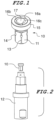
- Figure 1 depicts one embodiment of a displacer tool 10 intended for use in a standard CNC machine which applies both pressing and rotational forces to the punch fixture 12 such as seen in figure 2 .
- This embodiment is not encompassed by the scope of the appended claims but useful to understand the invention, the scope of which is defined by the appended claims.
- a complete description of a punch of this type is disclosed in pending co-owned US patent application 16/307 , 133. Using the tool tips 10 held within the punch 12 as described below, fasteners can be affixed to malleable metal panels. In all of these embodiments the panels are prepared with blind receiving holes.
- the main elements of the tool tip are a body 14 with attachment means 13 for being held within a rotary punch press fixture 12 as seen in Figure 2 .
- the working end of the tool has a flange 15 with an end face that has a plurality of displacers such as those shown at 16a,b,and c which surround a central bore 17 that holds the fastener while it is being installed.
- the tool is pressed to a given point and the tool is then rotated at that depth.
- Three separate displacers are shown, each with a different profile that acts upon the workpiece panel as the tool is rotated.
- Displacer 16a has a ramped profile that parts off the outside diameter of the metal which is pulled in and moves partially toward outside diameter of the fastener being installed. Its profile is vertically tapered along an arcuate ridge centered about the axial bore from a back end of the displacer of greatest height down to a front end of minimum height of the displacer where the ridge meets the end face. Displacer 16b, is like an additional snow plow that follows after the first displacer and has a configuration that moves the parted metal even closer to the outside periphery of the fastener being installed. And finally, displacer 16c, having a profile rectangular in section, then compresses the peak of displaced material to press the metal tightly down around the fastener.
- these displacers illustrate how different displacers while operating independently function together to form the desired sequential composite displacement of workpiece material 21.
- the panel material is reshaped around and above the outside of a flange 23 of fastener 25 which has been inserted into a blind hole of the receiving panel 24.
- the workpiece panel is cut into and deformed without any loss of panel material.
- rolling balls 41 are employed in a tool tip 40 to displace the panel material.
- panel material is moved by a continuous displacement method by a displacer ring 71 that wobbles.
- the displacer ring is loosely fitting to the tool body both radially and axially by attachment means 76 at the top to allow it to tip to one side or the other as the body is rotated.
- the displacer ring also has a raceway on which a single ball bearing 73 can travel which further functions to retain the ball 73 within the tool assembly.
- the displacer ring has a conical profile with a circular cutting edge 74.
- This displacer applies force to one portion of a full circle displacer through the single ball bearing 73 captivated to the tool body.
- the displacer tip is rotated and pushed into the panel, the displacer ring wobbles.
- the displacement force is applied following the ball bearing around the circumference of the installation causing the displacer to wobble, and thus pressing only a portion of the displacer ring cutting edge at point 75 into the panel at any one point in time.
- Figure 8 depicts another embodiment encompassed by the scope of the appended claims which utilizes an incremental displacer similar to that shown in Figure 7 .
- This displacer substitutes the ball and raceway structures of Figure 7 with a cone gear 82 meshed with two circular cone racks 84 and 85, one above and one below.
- the incorporation of a spring 87 is also added to illustrate how stability to the displacer tip can be added when and if necessary.
- the cone gear guarantees no slipping between the gear faces and consequently ensures s full 360 degrees of pressing per rotation of the tool body.
- displacers 94 are machined and polished rounded surfaces or rounded fixed pins forming a unitary part of the tool body 92.
- the displacers shown are spherical at any point where they can contact the panel 98 as seen in Figure 10 .
- Displacer geometry can also be wedge-shaped as in previous embodiments of this design.
- the tool body and displacers seen in figure 10 are unified in one solid machined body.
- the tool is incrementally stroked, and rotated between strokes of a given length which results in a workpiece deformation to a predetermined depth level.
- the tool is rotated a set amount (e.g. 20°) before the next stroke is applied. Installation is achieved in incrementally advancing displacement depth levels. The number of axial strokes per depth level is determined by the amount of rotation in the tool following each stroke.
- the stroke group is complete. The tool is then rotated a complete 360 degrees to smooth out the displaced material, and the process begins again at the next depth which are scalar increments of the initial depth.
- Table 1 below provides a breakdown of how installation is achieved via install groups. Each group corresponds to an install depth or 'level'. In this example the number of displacers is 6 (as in figure 8 ), and hence the distance between them is 60 degrees (360 / N). 1 inch is equivalent to 2.54 cm.
- install groups are customized for each part and correspond to blind hole depth, the number of displacers, and the angular distance between displacers. For instance, if there are 5 displacers the distance between them is 72 degrees. This distance is covered by any number of strokes depending on the amount of rotation per stroke. If the rotation per stroke is 12 degrees, then there are 5 strokes followed by a complete rotation of the tool occurring immediately after the final stroke. Individual displacers, whether ball or wedge are used specifically to minimize the projected area on panel while also moving enough material to achieve installation; this is the purpose of tool rotation following each stroke.
- Figure 10 is a section view of the oscillating tip not encompassed by the scope of the appended claims (fixed ball variant) after a part has been installed.
- the tip moves material over the part flange as in previous embodiments of this technology with the primary difference being kinetic interference friction is eliminated during the stroke process; rotation of the tool between strokes occurs free of contact with the panel 98. Additionally, compressive panel stress at points of deformation 97 is relieved completely after each stroke of the tool which initiates panel contact with the displacer at point 95.
- the oscillating tip achieves installation of the part using a series of composite strokes and rotations applied in groups and at successive install depth levels.
Landscapes
- Engineering & Computer Science (AREA)
- Mechanical Engineering (AREA)
- General Engineering & Computer Science (AREA)
- Shaping Metal By Deep-Drawing, Or The Like (AREA)
- Perforating, Stamping-Out Or Severing By Means Other Than Cutting (AREA)
- Jigs For Machine Tools (AREA)
- Insertion Pins And Rivets (AREA)
- Forging (AREA)
Claims (5)
- Werkzeugspitze (70, 80) für einen Stempel für eine Rundlaufpresse, umfassend:einen Körper (14), der einen Schaft (11) und einen sich radial erstreckenden Flansch (15) an dem Schaft (11) benachbart zu einem unteren Ende des Körpers (14) aufweist;eine axiale Bohrung (17) in dem Körper, die so konstruiert und konfiguriert ist, dass sie einen Befestiger hält, dadurch gekennzeichnet, dass sie ferner einen Verdrängerring (71, 88) umfasst, der an dem Körper (14) festgehalten und axial und radial lose an dem Schaft (11) befestigt ist, wobei der Ring eine 360-Winkelgrad-Schneidkante (74) an der Unterseite davon aufweist; undKraftübertragungsmittel (73, 82), die sich zwischen dem Flansch (15) und dem Verdrängerring (71, 88) befinden und so konstruiert und konfiguriert sind, dass sie eine Druckkraft von dem Schaft (11) auf den Ring (71, 88) an einem einzigen Punkt auf dem Ring (75) so übertragen, dass, wenn das Werkzeug gegen ein Werkstück gedrückt und es rotiert wird, der Ring (71, 88) eine Taumelbewegung durchführt, die nur einen Abschnitt der Schneidkante (75) gegen das Werkstück drückt.
- Werkzeugspitze nach Anspruch 1, wobei das Kraftübertragungsmittel ein einzelnes Kugellager (73) ist.
- Werkzeugspitze nach Anspruch 1, wobei das Kraftübertragungsmittel ein Ritzel (82) ist, das mit einem oberen Hohlrad (84), das an dem Flansch (15) befestigt ist, und einem unteren Hohlrad (85), das an dem Verdrängerring (88) befestigt ist, im Eingriff steht.
- Werkzeugspitze nach Anspruch 1 oder 3, ferner umfassend eine Feder (87), die zwischen einem zweiten Flansch am unteren Ende des Körpers (14) und einer Innenfläche an der Oberseite des Verdrängerrings (88) betriebsfähig ist.
- Verwendung einer Rundlaufpresse, die einem Werkstückmaterial sowohl eine Rotation als auch eine Presskraft verleiht, um einen Klammerbefestiger in das Werkstückmaterial zu installieren, wobei die Rundlaufpresse eine Werkzeugspitze nach einem der Ansprüche 1 bis 4 beinhaltet.
Priority Applications (1)
| Application Number | Priority Date | Filing Date | Title |
|---|---|---|---|
| EP25170594.3A EP4563286A3 (de) | 2020-04-23 | 2021-04-21 | Rotierende installationswerkzeuge für klammerbefestiger |
Applications Claiming Priority (3)
| Application Number | Priority Date | Filing Date | Title |
|---|---|---|---|
| US202063014417P | 2020-04-23 | 2020-04-23 | |
| US202063033098P | 2020-06-01 | 2020-06-01 | |
| PCT/US2021/028287 WO2021216632A1 (en) | 2020-04-23 | 2021-04-21 | Rotary installation tools for clinch fasteners |
Related Child Applications (2)
| Application Number | Title | Priority Date | Filing Date |
|---|---|---|---|
| EP25170594.3A Division-Into EP4563286A3 (de) | 2020-04-23 | 2021-04-21 | Rotierende installationswerkzeuge für klammerbefestiger |
| EP25170594.3A Division EP4563286A3 (de) | 2020-04-23 | 2021-04-21 | Rotierende installationswerkzeuge für klammerbefestiger |
Publications (3)
| Publication Number | Publication Date |
|---|---|
| EP4139068A1 EP4139068A1 (de) | 2023-03-01 |
| EP4139068A4 EP4139068A4 (de) | 2024-03-27 |
| EP4139068B1 true EP4139068B1 (de) | 2025-05-28 |
Family
ID=78221604
Family Applications (2)
| Application Number | Title | Priority Date | Filing Date |
|---|---|---|---|
| EP21793372.0A Active EP4139068B1 (de) | 2020-04-23 | 2021-04-21 | Rotierende installationswerkzeuge für klammerbefestiger |
| EP25170594.3A Withdrawn EP4563286A3 (de) | 2020-04-23 | 2021-04-21 | Rotierende installationswerkzeuge für klammerbefestiger |
Family Applications After (1)
| Application Number | Title | Priority Date | Filing Date |
|---|---|---|---|
| EP25170594.3A Withdrawn EP4563286A3 (de) | 2020-04-23 | 2021-04-21 | Rotierende installationswerkzeuge für klammerbefestiger |
Country Status (8)
| Country | Link |
|---|---|
| US (2) | US12115631B2 (de) |
| EP (2) | EP4139068B1 (de) |
| JP (1) | JP2023522677A (de) |
| CN (1) | CN115803129A (de) |
| CA (1) | CA3180805A1 (de) |
| MX (1) | MX2022013190A (de) |
| TW (1) | TWI879945B (de) |
| WO (1) | WO2021216632A1 (de) |
Families Citing this family (3)
| Publication number | Priority date | Publication date | Assignee | Title |
|---|---|---|---|---|
| US20240376923A1 (en) * | 2023-05-11 | 2024-11-14 | Profil Verbindungstechnik Gmbh & Co. Kg | Self-Punching Functional Element |
| CN117564955B (zh) * | 2023-09-15 | 2025-09-30 | 南京航空航天大学 | 压致转轻量化紧固工具结构及其基于4d打印技术的制备方法 |
| CN117840944A (zh) * | 2023-12-19 | 2024-04-09 | 华能伊敏煤电有限责任公司 | 一种发动机缸盖装配拆卸辅助工具 |
Family Cites Families (24)
| Publication number | Priority date | Publication date | Assignee | Title |
|---|---|---|---|---|
| US133A (en) | 1837-03-03 | benjamin bull | ||
| US16307A (en) | 1856-12-23 | Improvement in automatic rakes for harvesters | ||
| US1842571A (en) * | 1929-12-26 | 1932-01-26 | Arthur H Parker | Method of applying bail ears to containers |
| US4018257A (en) * | 1975-12-15 | 1977-04-19 | Cold Fasteners, Inc. | Self-flanging nut and joint construction |
| DE2607334A1 (de) | 1976-02-23 | 1977-08-25 | Goetz Metallbau Gmbh | Verfahren zur befestigung von verankerungsbolzen an metall-fassadenplatten bzw. befestigungsvorrichtung fuer metall-fassadenplatten |
| US4402124A (en) * | 1982-01-25 | 1983-09-06 | Guenther Krueger | Method of pressure locking an aperatured nut into a die-side hole of a metal plate |
| DE3507489A1 (de) * | 1985-03-02 | 1986-04-30 | Daimler-Benz Ag, 7000 Stuttgart | Verfahren zum einseitigen, unloesbaren befestigen eines bolzens an einem metall-holzlaminat, sowie eine es ausfuehrende taumelnieteinrichtung |
| JPS6415630U (de) * | 1987-07-21 | 1989-01-26 | ||
| US5338139A (en) * | 1993-10-20 | 1994-08-16 | Penn Engineering & Manufacturing Corp. | Shrouded captive screw |
| US5655396A (en) | 1995-09-25 | 1997-08-12 | General Motors Corporation | Roll peening device |
| US6077003A (en) * | 1998-06-16 | 2000-06-20 | Hydra-Lock Corporation | Tool holder |
| US6527489B2 (en) * | 2000-12-07 | 2003-03-04 | International Business Machines Corporation | Concealed low distorting self crimping stud and insertion method |
| US6908690B2 (en) * | 2002-04-29 | 2005-06-21 | The Boeing Company | Method and apparatus for friction stir welding |
| US20040042871A1 (en) * | 2002-09-04 | 2004-03-04 | Wojciechowski Stanley E. | Self-attaching female fastener element, sealed fastener and panel assembly and method of forming same |
| JP4002171B2 (ja) * | 2002-11-26 | 2007-10-31 | カルソニックカンセイ株式会社 | パイプの接続構造、パイプの接続方法及び加締め金型 |
| DE102004020676A1 (de) * | 2004-04-28 | 2005-11-24 | Profil-Verbindungstechnik Gmbh & Co. Kg | Verfahren und Vorrichtung zur Anbringung eines Befestigungselements an ein Bauteil, insbesondere an ein Blechteil |
| US7480971B2 (en) * | 2005-04-28 | 2009-01-27 | Profile Verbindungstechnik Gmbh & Co., Kg | Method and device for mounting a fastener element on a part, particularly a sheet metal part |
| CN103894814A (zh) * | 2012-12-27 | 2014-07-02 | 鸿富锦精密工业(深圳)有限公司 | 铆合装置 |
| DE102014117401A1 (de) * | 2014-11-27 | 2016-06-02 | Tkr Spezialwerkzeuge Gmbh | Nietwerkzeug |
| DE102015109255A1 (de) * | 2015-06-11 | 2016-12-15 | Profil Verbindungstechnik Gmbh & Co. Kg | Verfahren zum Befestigen eines Nietelements und entsprechendes Befestigungssystem |
| DE102015109244A1 (de) * | 2015-06-11 | 2016-12-15 | Profil Verbindungstechnik Gmbh & Co. Kg | Verfahren zum Befestigen eines Nietelements und entsprechendes Befestigungssystem hierfür |
| WO2018044848A1 (en) * | 2016-08-29 | 2018-03-08 | Penn Engineering & Manufacturing Corp. | Fastener for thin-sheet materials |
| TWI809556B (zh) * | 2017-05-09 | 2023-07-21 | 美商賓工程工廠公司 | 緊固件安裝系統 |
| CA3126013C (en) * | 2019-01-08 | 2024-01-02 | Acument Intellectual Properties, Llc | Clinch fastener |
-
2021
- 2021-04-21 WO PCT/US2021/028287 patent/WO2021216632A1/en not_active Ceased
- 2021-04-21 JP JP2022563174A patent/JP2023522677A/ja not_active Ceased
- 2021-04-21 MX MX2022013190A patent/MX2022013190A/es unknown
- 2021-04-21 CN CN202180043893.6A patent/CN115803129A/zh not_active Withdrawn
- 2021-04-21 EP EP21793372.0A patent/EP4139068B1/de active Active
- 2021-04-21 CA CA3180805A patent/CA3180805A1/en active Pending
- 2021-04-21 US US17/236,033 patent/US12115631B2/en active Active
- 2021-04-21 EP EP25170594.3A patent/EP4563286A3/de not_active Withdrawn
- 2021-04-23 TW TW110114621A patent/TWI879945B/zh active
-
2024
- 2024-07-23 US US18/780,723 patent/US12594652B2/en active Active
Also Published As
| Publication number | Publication date |
|---|---|
| EP4563286A2 (de) | 2025-06-04 |
| US12115631B2 (en) | 2024-10-15 |
| US12594652B2 (en) | 2026-04-07 |
| EP4563286A3 (de) | 2025-06-11 |
| CN115803129A (zh) | 2023-03-14 |
| US20210331227A1 (en) | 2021-10-28 |
| TWI879945B (zh) | 2025-04-11 |
| CA3180805A1 (en) | 2021-10-28 |
| JP2023522677A (ja) | 2023-05-31 |
| EP4139068A1 (de) | 2023-03-01 |
| EP4139068A4 (de) | 2024-03-27 |
| MX2022013190A (es) | 2023-01-05 |
| WO2021216632A1 (en) | 2021-10-28 |
| TW202202245A (zh) | 2022-01-16 |
| US20240375254A1 (en) | 2024-11-14 |
Similar Documents
| Publication | Publication Date | Title |
|---|---|---|
| US12594652B2 (en) | Rotary installation tools for clinch fasteners | |
| US11969840B2 (en) | Method of fastening a fastener | |
| MXPA05004009A (es) | Elemento sujetador resistente al par. | |
| EP1915225B1 (de) | Verfahren zur erzeugung von innen- und aussenverzahnungen an dünnwandigen, zylindrischen hohlteilen | |
| DE3215923A1 (de) | Drehmomentabhaengige anpressvorrichtung fuer ein stufenlos einstellbares kugelplanetengetriebe | |
| MXPA05010779A (es) | Elemento sujetador resistente a par. | |
| CN114776681B (zh) | 铆接方法及铆接结构 | |
| WO2018044848A1 (en) | Fastener for thin-sheet materials | |
| RU2323060C2 (ru) | Способ изготовления компонента, имеющего зубья с внутренним зацеплением, и зубонакатный станок для его осуществления | |
| US4100784A (en) | Finned tubing | |
| DE202004021831U1 (de) | Bauteil | |
| DE102004052053A1 (de) | Verfahren zum Befestigen eines Bauteils in einer Baukomponente |
Legal Events
| Date | Code | Title | Description |
|---|---|---|---|
| STAA | Information on the status of an ep patent application or granted ep patent |
Free format text: STATUS: THE INTERNATIONAL PUBLICATION HAS BEEN MADE |
|
| PUAI | Public reference made under article 153(3) epc to a published international application that has entered the european phase |
Free format text: ORIGINAL CODE: 0009012 |
|
| STAA | Information on the status of an ep patent application or granted ep patent |
Free format text: STATUS: REQUEST FOR EXAMINATION WAS MADE |
|
| 17P | Request for examination filed |
Effective date: 20221102 |
|
| AK | Designated contracting states |
Kind code of ref document: A1 Designated state(s): AL AT BE BG CH CY CZ DE DK EE ES FI FR GB GR HR HU IE IS IT LI LT LU LV MC MK MT NL NO PL PT RO RS SE SI SK SM TR |
|
| DAV | Request for validation of the european patent (deleted) | ||
| DAX | Request for extension of the european patent (deleted) | ||
| A4 | Supplementary search report drawn up and despatched |
Effective date: 20240223 |
|
| RIC1 | Information provided on ipc code assigned before grant |
Ipc: B25B 27/00 20060101ALI20240219BHEP Ipc: F16B 37/06 20060101ALI20240219BHEP Ipc: B21K 25/00 20060101ALI20240219BHEP Ipc: B23P 11/00 20060101ALI20240219BHEP Ipc: B23P 19/06 20060101ALI20240219BHEP Ipc: B21J 15/12 20060101AFI20240219BHEP |
|
| GRAP | Despatch of communication of intention to grant a patent |
Free format text: ORIGINAL CODE: EPIDOSNIGR1 |
|
| STAA | Information on the status of an ep patent application or granted ep patent |
Free format text: STATUS: GRANT OF PATENT IS INTENDED |
|
| INTG | Intention to grant announced |
Effective date: 20250211 |
|
| GRAS | Grant fee paid |
Free format text: ORIGINAL CODE: EPIDOSNIGR3 |
|
| GRAA | (expected) grant |
Free format text: ORIGINAL CODE: 0009210 |
|
| STAA | Information on the status of an ep patent application or granted ep patent |
Free format text: STATUS: THE PATENT HAS BEEN GRANTED |
|
| AK | Designated contracting states |
Kind code of ref document: B1 Designated state(s): AL AT BE BG CH CY CZ DE DK EE ES FI FR GB GR HR HU IE IS IT LI LT LU LV MC MK MT NL NO PL PT RO RS SE SI SK SM TR |
|
| REG | Reference to a national code |
Ref country code: GB Ref legal event code: FG4D |
|
| REG | Reference to a national code |
Ref country code: CH Ref legal event code: EP |
|
| REG | Reference to a national code |
Ref country code: IE Ref legal event code: FG4D Ref country code: DE Ref legal event code: R096 Ref document number: 602021031479 Country of ref document: DE |
|
| REG | Reference to a national code |
Ref country code: NL Ref legal event code: MP Effective date: 20250528 |
|
| PG25 | Lapsed in a contracting state [announced via postgrant information from national office to epo] |
Ref country code: ES Free format text: LAPSE BECAUSE OF FAILURE TO SUBMIT A TRANSLATION OF THE DESCRIPTION OR TO PAY THE FEE WITHIN THE PRESCRIBED TIME-LIMIT Effective date: 20250528 Ref country code: FI Free format text: LAPSE BECAUSE OF FAILURE TO SUBMIT A TRANSLATION OF THE DESCRIPTION OR TO PAY THE FEE WITHIN THE PRESCRIBED TIME-LIMIT Effective date: 20250528 |
|
| REG | Reference to a national code |
Ref country code: LT Ref legal event code: MG9D |
|
| PG25 | Lapsed in a contracting state [announced via postgrant information from national office to epo] |
Ref country code: GR Free format text: LAPSE BECAUSE OF FAILURE TO SUBMIT A TRANSLATION OF THE DESCRIPTION OR TO PAY THE FEE WITHIN THE PRESCRIBED TIME-LIMIT Effective date: 20250829 Ref country code: NO Free format text: LAPSE BECAUSE OF FAILURE TO SUBMIT A TRANSLATION OF THE DESCRIPTION OR TO PAY THE FEE WITHIN THE PRESCRIBED TIME-LIMIT Effective date: 20250828 |
|
| PG25 | Lapsed in a contracting state [announced via postgrant information from national office to epo] |
Ref country code: NL Free format text: LAPSE BECAUSE OF FAILURE TO SUBMIT A TRANSLATION OF THE DESCRIPTION OR TO PAY THE FEE WITHIN THE PRESCRIBED TIME-LIMIT Effective date: 20250528 Ref country code: PL Free format text: LAPSE BECAUSE OF FAILURE TO SUBMIT A TRANSLATION OF THE DESCRIPTION OR TO PAY THE FEE WITHIN THE PRESCRIBED TIME-LIMIT Effective date: 20250528 |
|
| PG25 | Lapsed in a contracting state [announced via postgrant information from national office to epo] |
Ref country code: BG Free format text: LAPSE BECAUSE OF FAILURE TO SUBMIT A TRANSLATION OF THE DESCRIPTION OR TO PAY THE FEE WITHIN THE PRESCRIBED TIME-LIMIT Effective date: 20250528 |
|
| PG25 | Lapsed in a contracting state [announced via postgrant information from national office to epo] |
Ref country code: HR Free format text: LAPSE BECAUSE OF FAILURE TO SUBMIT A TRANSLATION OF THE DESCRIPTION OR TO PAY THE FEE WITHIN THE PRESCRIBED TIME-LIMIT Effective date: 20250528 |
|
| PG25 | Lapsed in a contracting state [announced via postgrant information from national office to epo] |
Ref country code: RS Free format text: LAPSE BECAUSE OF FAILURE TO SUBMIT A TRANSLATION OF THE DESCRIPTION OR TO PAY THE FEE WITHIN THE PRESCRIBED TIME-LIMIT Effective date: 20250828 |
|
| PG25 | Lapsed in a contracting state [announced via postgrant information from national office to epo] |
Ref country code: IS Free format text: LAPSE BECAUSE OF FAILURE TO SUBMIT A TRANSLATION OF THE DESCRIPTION OR TO PAY THE FEE WITHIN THE PRESCRIBED TIME-LIMIT Effective date: 20250928 |
|
| PG25 | Lapsed in a contracting state [announced via postgrant information from national office to epo] |
Ref country code: LV Free format text: LAPSE BECAUSE OF FAILURE TO SUBMIT A TRANSLATION OF THE DESCRIPTION OR TO PAY THE FEE WITHIN THE PRESCRIBED TIME-LIMIT Effective date: 20250528 |
|
| REG | Reference to a national code |
Ref country code: AT Ref legal event code: MK05 Ref document number: 1798357 Country of ref document: AT Kind code of ref document: T Effective date: 20250528 |
|
| PG25 | Lapsed in a contracting state [announced via postgrant information from national office to epo] |
Ref country code: AT Free format text: LAPSE BECAUSE OF FAILURE TO SUBMIT A TRANSLATION OF THE DESCRIPTION OR TO PAY THE FEE WITHIN THE PRESCRIBED TIME-LIMIT Effective date: 20250528 Ref country code: DK Free format text: LAPSE BECAUSE OF FAILURE TO SUBMIT A TRANSLATION OF THE DESCRIPTION OR TO PAY THE FEE WITHIN THE PRESCRIBED TIME-LIMIT Effective date: 20250528 Ref country code: SM Free format text: LAPSE BECAUSE OF FAILURE TO SUBMIT A TRANSLATION OF THE DESCRIPTION OR TO PAY THE FEE WITHIN THE PRESCRIBED TIME-LIMIT Effective date: 20250528 |
|
| PG25 | Lapsed in a contracting state [announced via postgrant information from national office to epo] |
Ref country code: CZ Free format text: LAPSE BECAUSE OF FAILURE TO SUBMIT A TRANSLATION OF THE DESCRIPTION OR TO PAY THE FEE WITHIN THE PRESCRIBED TIME-LIMIT Effective date: 20250528 |
|
| PG25 | Lapsed in a contracting state [announced via postgrant information from national office to epo] |
Ref country code: EE Free format text: LAPSE BECAUSE OF FAILURE TO SUBMIT A TRANSLATION OF THE DESCRIPTION OR TO PAY THE FEE WITHIN THE PRESCRIBED TIME-LIMIT Effective date: 20250528 |
|
| PG25 | Lapsed in a contracting state [announced via postgrant information from national office to epo] |
Ref country code: SK Free format text: LAPSE BECAUSE OF FAILURE TO SUBMIT A TRANSLATION OF THE DESCRIPTION OR TO PAY THE FEE WITHIN THE PRESCRIBED TIME-LIMIT Effective date: 20250528 |
|
| PG25 | Lapsed in a contracting state [announced via postgrant information from national office to epo] |
Ref country code: IT Free format text: LAPSE BECAUSE OF FAILURE TO SUBMIT A TRANSLATION OF THE DESCRIPTION OR TO PAY THE FEE WITHIN THE PRESCRIBED TIME-LIMIT Effective date: 20250528 |
|
| REG | Reference to a national code |
Ref country code: DE Ref legal event code: R097 Ref document number: 602021031479 Country of ref document: DE |
|
| PLBE | No opposition filed within time limit |
Free format text: ORIGINAL CODE: 0009261 |
|
| STAA | Information on the status of an ep patent application or granted ep patent |
Free format text: STATUS: NO OPPOSITION FILED WITHIN TIME LIMIT |
|
| REG | Reference to a national code |
Ref country code: CH Ref legal event code: L10 Free format text: ST27 STATUS EVENT CODE: U-0-0-L10-L00 (AS PROVIDED BY THE NATIONAL OFFICE) Effective date: 20260409 |
|
| 26N | No opposition filed |
Effective date: 20260303 |
|
| PG25 | Lapsed in a contracting state [announced via postgrant information from national office to epo] |
Ref country code: LT Free format text: LAPSE BECAUSE OF FAILURE TO SUBMIT A TRANSLATION OF THE DESCRIPTION OR TO PAY THE FEE WITHIN THE PRESCRIBED TIME-LIMIT Effective date: 20250528 |
|
| PG25 | Lapsed in a contracting state [announced via postgrant information from national office to epo] |
Ref country code: SE Free format text: LAPSE BECAUSE OF FAILURE TO SUBMIT A TRANSLATION OF THE DESCRIPTION OR TO PAY THE FEE WITHIN THE PRESCRIBED TIME-LIMIT Effective date: 20250528 |