EP4139859B1 - Procédé et système pour la coupe automatique de pièces dans un matériau souple conditionné sous forme de rouleau - Google Patents
Procédé et système pour la coupe automatique de pièces dans un matériau souple conditionné sous forme de rouleau Download PDFInfo
- Publication number
- EP4139859B1 EP4139859B1 EP21742455.5A EP21742455A EP4139859B1 EP 4139859 B1 EP4139859 B1 EP 4139859B1 EP 21742455 A EP21742455 A EP 21742455A EP 4139859 B1 EP4139859 B1 EP 4139859B1
- Authority
- EP
- European Patent Office
- Prior art keywords
- parts
- placement
- cutting
- new
- initial
- Prior art date
- Legal status (The legal status is an assumption and is not a legal conclusion. Google has not performed a legal analysis and makes no representation as to the accuracy of the status listed.)
- Active
Links
Images


Classifications
-
- B—PERFORMING OPERATIONS; TRANSPORTING
- B26—HAND CUTTING TOOLS; CUTTING; SEVERING
- B26D—CUTTING; DETAILS COMMON TO MACHINES FOR PERFORATING, PUNCHING, CUTTING-OUT, STAMPING-OUT OR SEVERING
- B26D5/00—Arrangements for operating and controlling machines or devices for cutting, cutting-out, stamping-out, punching, perforating, or severing by means other than cutting
-
- G—PHYSICS
- G06—COMPUTING OR CALCULATING; COUNTING
- G06Q—INFORMATION AND COMMUNICATION TECHNOLOGY [ICT] SPECIALLY ADAPTED FOR ADMINISTRATIVE, COMMERCIAL, FINANCIAL, MANAGERIAL OR SUPERVISORY PURPOSES; SYSTEMS OR METHODS SPECIALLY ADAPTED FOR ADMINISTRATIVE, COMMERCIAL, FINANCIAL, MANAGERIAL OR SUPERVISORY PURPOSES, NOT OTHERWISE PROVIDED FOR
- G06Q10/00—Administration; Management
- G06Q10/04—Forecasting or optimisation specially adapted for administrative or management purposes, e.g. linear programming or "cutting stock problem"
- G06Q10/043—Optimisation of two dimensional placement, e.g. cutting of clothes or wood
-
- B—PERFORMING OPERATIONS; TRANSPORTING
- B26—HAND CUTTING TOOLS; CUTTING; SEVERING
- B26F—PERFORATING; PUNCHING; CUTTING-OUT; STAMPING-OUT; SEVERING BY MEANS OTHER THAN CUTTING
- B26F1/00—Perforating; Punching; Cutting-out; Stamping-out; Apparatus therefor
- B26F1/38—Cutting-out; Stamping-out
-
- B—PERFORMING OPERATIONS; TRANSPORTING
- B26—HAND CUTTING TOOLS; CUTTING; SEVERING
- B26F—PERFORATING; PUNCHING; CUTTING-OUT; STAMPING-OUT; SEVERING BY MEANS OTHER THAN CUTTING
- B26F1/00—Perforating; Punching; Cutting-out; Stamping-out; Apparatus therefor
- B26F1/38—Cutting-out; Stamping-out
- B26F1/3806—Cutting-out; Stamping-out wherein relative movements of tool head and work during cutting have a component tangential to the work surface
-
- G—PHYSICS
- G06—COMPUTING OR CALCULATING; COUNTING
- G06Q—INFORMATION AND COMMUNICATION TECHNOLOGY [ICT] SPECIALLY ADAPTED FOR ADMINISTRATIVE, COMMERCIAL, FINANCIAL, MANAGERIAL OR SUPERVISORY PURPOSES; SYSTEMS OR METHODS SPECIALLY ADAPTED FOR ADMINISTRATIVE, COMMERCIAL, FINANCIAL, MANAGERIAL OR SUPERVISORY PURPOSES, NOT OTHERWISE PROVIDED FOR
- G06Q50/00—Information and communication technology [ICT] specially adapted for implementation of business processes of specific business sectors, e.g. utilities or tourism
- G06Q50/04—Manufacturing
-
- B—PERFORMING OPERATIONS; TRANSPORTING
- B26—HAND CUTTING TOOLS; CUTTING; SEVERING
- B26D—CUTTING; DETAILS COMMON TO MACHINES FOR PERFORATING, PUNCHING, CUTTING-OUT, STAMPING-OUT OR SEVERING
- B26D5/00—Arrangements for operating and controlling machines or devices for cutting, cutting-out, stamping-out, punching, perforating, or severing by means other than cutting
- B26D2005/002—Performing a pattern matching operation
-
- B—PERFORMING OPERATIONS; TRANSPORTING
- B26—HAND CUTTING TOOLS; CUTTING; SEVERING
- B26F—PERFORATING; PUNCHING; CUTTING-OUT; STAMPING-OUT; SEVERING BY MEANS OTHER THAN CUTTING
- B26F2210/00—Perforating, punching, cutting-out, stamping-out, severing by means other than cutting of specific products
- B26F2210/12—Perforating, punching, cutting-out, stamping-out, severing by means other than cutting of specific products of fabrics
Definitions
- the invention relates to the general field of automatic cutting of parts in a flexible material packaged in roll form. It concerns more particularly the management of triggering events occurring during cutting on the parts and likely to affect the quality and yield of the cut.
- Areas of application of the invention include the clothing and furniture industries.
- EP 0 759 708 describes a method for automatically cutting pieces from patterned fabric anticipating the preamble of claims 1 and 16.
- Automatic cutting of parts in a flexible material is typically carried out on a conveyor cutting machine controlled from a control station.
- the cutting process takes place as follows.
- the operator receives at the control station a list of cutting jobs to be carried out which has been prepared in advance.
- Each of these jobs contains all the information necessary to make a cut, namely: a placement of the pieces to be cut and a material on which the cut will be made.
- the materials used are generally packaged in the form of rolls which are loaded onto the supply module of the cutting machine.
- the material is then transported gradually using the conveyor to the different modules of the cutting machine, namely: a cutting module at which the cutting of the parts takes place, and an unloading module where the operator recovers the cut parts.
- a material acquisition module is also provided to scan it upstream of the cutting module.
- the placement of the parts is designed to optimize material consumption as much as possible but also to obtain a high quality cutting result.
- constraints can be imposed by the cutting support.
- the usable web width may impose a limitation on the part placement area.
- the type of material used may impose a minimum proximity distance between certain parts.
- constraints imposed by the cutting support can be imposed by designers and modelers during the creation phase. This may involve, for example, respecting the straight grain of the fabric which imposes defined rotation values, or, in the case of patterned fabrics, connection constraints which impose a position dependence between the pieces.
- the system will activate the supply module automatically from the material data contained in the first cutting job in the list.
- the operator will be able to load the roll corresponding to the material given to him.
- the operator will be able to specify the direction and visible side of the material. This action will be done either on the cockpit or on the supply module.
- the material is routed to the cutting module while passing through the possible acquisition module.
- the latter makes it possible to digitize the material spread out on the cutting table and to give the real characteristics of the material to the operator.
- the operator positions the placement in the right place on it using the image provided by the acquisition module or with a pointing tool on board the cutting head. cutting and cutting can begin.
- one of the known solutions consists of asking the operator to show the end of the current roller to split the placement into two parts so as to avoid the "change" zone between the rollers.
- FIG. 1A This solution of the prior art is illustrated by the Figures 1A to 1C .
- FIG. 1A On the Figure 1A , are represented a plurality of parts P1 to P10 of a placement being cut. Parts P1 to P3 have already been cut from the current roll Rc (and which have reached the unloading module), part P4 is being cut, while parts P5 to P10 are not yet cut (or partially cut , or even completely cut). Furthermore, we notice on this Figure 1A that the pieces P5 and P6 are positioned astride the end of the current roll Rc (on which the pieces P1 to P4 are cut) and the pieces P7 to P10 are positioned beyond the end of the current roll.
- the operator delimits a roller change zone Z represented on the Figure 1B .
- the pieces P5 to P7 which are located in this zone Z will not be cut on the current roll Rc and will be placed on the next roll Rs to be cut there. More precisely, the placement of pieces P1 to P10 is split in two with pieces P5 to P10 which will be shifted in the placement to be cut into the next roll Rs.
- the operator may notice a defect on a part making it unusable. In this case, he has the possibility of “rejecting” it. Once the placement has been completely cut and unloaded, all of the rejected parts are then recut by assigning them to a new placement.
- the present invention therefore aims to propose a cutting process which does not present the aforementioned drawbacks when a triggering event occurs during the cutting of the placement.
- the method according to the invention is remarkable in that it provides, in the event of receipt of a triggering event during the cutting of the placement, to automatically develop a list of parts to be kept, then to develop a new placement different from the initial placement, this new placement taking into account the position of the parts to be kept and calculating new positions for all or part of the other parts to be repositioned.
- the method according to the invention proposes to carry out a re-calculation of the placement of all or part of the other parts to be repositioned to generate a new optimized placement allowing significant material savings.
- new placement we mean here a placement of the parts to be repositioned in their entirety which is developed without taking into account the position of the parts as defined in the initial placement. In particular, this new placement is not just a simple optimization of the initial placement.
- the method according to the invention makes it possible to obtain significant productivity gains insofar as it is possible to maintain a minimum cutting time during which the new placement is generated, which avoids any stoppage in production. .
- step e) is followed by a step f) of automatically cutting the parts in the material spread out on the cutting table according to the new placement.
- the new placement developed in step e) may include all or part of the pieces from the initial placement still remaining to be cut.
- the new placement developed in step e) may also include one or more parts for which the placement is no longer adapted to the cutting environment.
- step d) comprises the determination of the number of pieces to be kept still remaining to be cut based on an evaluation of their cutting time and the time allocated to calculating the new placement.
- the time allocated to the calculation of the new placement is advantageously less than the evaluation of the cutting time of the parts to be kept still remaining to be cut.
- the selection of the pieces of the new placement among all the pieces of the initial placement still to be cut is carried out while respecting any constraints on the placement of said pieces.
- the triggering event can be chosen from: detection of the end of the roll on which the material spread on the cutting table is packaged, detection of a defect on the material spread on the cutting table, and detection of a defect on a cut part that requires it to be recut.
- step e) may include the establishment of a first placement of parts on the end of the roll, and a second placement of the remaining pieces on another roll of material.
- step e) may include the exclusion of the area of the spread material on which the defect is present to establish the new placement .
- step e) may include adding the defective part to the new placement.
- step e) is designed to minimize any loss of productivity.
- step e) can be carried out without interrupting the cutting of the parts to be kept remaining to be cut according to the initial placement.
- step e) of developing the new placement is carried out iteratively in order to obtain the highest possible efficiency rate.
- Step c) may include a prior step of modifying the initial placement to generate a real placement of the parts on the spread material which takes into account the real characteristics of the material.
- the invention relates to the automatic cutting of a plurality of parts in a flexible material packaged in the form of a roll by means of a cutting system such as that shown in the figure 2 .
- such a cutting system 2 can be made up of four modules through which the material passes, namely (from upstream to downstream in the direction of advance F of the material): a supply module 4 positioned at one end of the cutting table 6, an acquisition module 8 (optional), a cutting module 10, and an unloading module 12 positioned at another end of the cutting table.
- the supply module 4 is intended to receive the material to be cut packaged in roll form.
- the acquisition module 8 is an optional module which is intended to scan the material spread on the cutting table.
- the cutting module 10 comprises a mobile gantry 10a on which a cutting tool is mounted for cutting the parts.
- the unloading module 12 it is used by the operator to unload the cut parts outside the table.
- the flexible material to be cut is driven onto the cutting table 2 by a conveyor from the supply module 4 to the unloading module 12.
- the cutting system 2 also includes a control station 14 allowing the operator to program control of the different modules depending on the material to be cut and the cutting work to be carried out.
- the operator receives at the control station 14 from a computer workstation 15 the information necessary to carry out a cut, namely (for each cutting job): an initial placement of a list of parts to be cut, and a material on which the cut is to be made.
- the soft material of a cutting job represents the fabric from which the pieces are to be cut.
- Each material is associated with a set of previously recorded technical characteristics (in particular the color, the description of a possible pattern, the width of the width, etc.).
- FIG. 3 is a flowchart of the different stages of the process according to the invention for the automatic cutting of parts in a flexible material packaged in the form of a roll, these different stages being implemented in particular using a cutting system such as that described in connection with the figure 2 .
- the first step S1 of the process consists of developing an initial placement for a list of parts to be cut from the flexible material.
- the placement is carried out manually or automatically, most often by a dedicated operator (different from the one handling the cutting system), in order to optimize material consumption as much as possible but also to obtain a high quality cutting result. .
- the placement takes into account the constraints imposed by the cutting support, such as for example the width of the width (which imposes a limitation on the placement area) and the type of material used (which imposes a minimum proximity distance between the pieces), but also constraints imposed by the designer and/or model maker, such as for example respecting the straight grain of the fabric and, in the case of a patterned fabric, the connection constraints between the pieces and of stitch pattern.
- constraints imposed by the cutting support such as for example the width of the width (which imposes a limitation on the placement area) and the type of material used (which imposes a minimum proximity distance between the pieces), but also constraints imposed by the designer and/or model maker, such as for example respecting the straight grain of the fabric and, in the case of a patterned fabric, the connection constraints between the pieces and of stitch pattern.
- the initial placement is developed taking into account the connection constraints between the pieces.
- the next step S2 of the method according to the invention consists of spreading a layer of material to be cut on the cutting table.
- the cutting system will activate the supply module automatically from the material data contained in the first cutting job in the list. On the supply module, the operator will be able to load the roll corresponding to the material given to him.
- This supply module is generally equipped with sensors and actuators to ensure the unwinding of the roll and a tension-free, wrinkle-free and well-aligned fabric deposit.
- This module is generally equipped with a fabric presence detector. This detector can identify the end of a roll. Measuring the fabric tension also makes it possible to detect the end of the roll in the case where the end of the fabric is stuck to the central roll core.
- the material is then conveyed on the cutting table to the cutting module.
- the tissue can pass through an acquisition module where new information about the material is recorded.
- This acquisition module can be a scanner recording and analyzing an image of the material, a simple detector placed above the edge of the fabric and detecting a mark indicating the presence of a defect on the fabric or any other device providing information on the material before cutting (step S3).
- This step S3 makes it possible to take into account possible differences which may exist between the theoretical information of the material (given beforehand in the cutting work) and the real information observed by the operator or specific to the roll being cut. These differences are due to printing defects, defects in placing fabric on the cutting table, variations in density of threads of the loom and/or deformations of the fabric which can result in irregularities in the pitch. repeating the pattern.
- step S4 it is planned to automatically modify or adjust the initial placement (step S4) so that it can correspond to the reality of the fabric spread on the cutting table.
- An example of changing the initial placement is described in the publication EP 0,759,708 .
- step S5 of the method according to the invention then consists of starting the cutting of the initial placement (possibly modified during step S4). This operation is carried out at the cutting module of the cutting system.
- the material moves on the cutting table and the different pieces are cut according to the initial placement possibly modified.
- a triggering event Evt occurs.
- Different types of trigger events are concerned here: detection of the end of the roll on which the material spread on the cutting table is packaged, detection of a defect on the material spread on the cutting table, and detection of 'a defect on an already cut part which requires it to be recut.
- This triggering event can occur automatically (for example in the case of a defect on the material spread on the cutting table which can be detected by the acquisition module of the cutting system) or manually by the operator.
- a list of parts to be kept is automatically created (step S6 of the process).
- the parts in this list are the parts for which the new placement developed in the next step S7 will not modify the position. For example, parts that have already been cut and do not need to be recut are part of this list of parts to keep.
- the automatic placement module automatically develops a new placement.
- This new placement is developed independently of the initial placement developed in step S1.
- the new placement nevertheless takes into account the position of the parts to be kept (from step S6) and calculates new positions for all or part of the other parts (called parts to be repositioned), these new positions not taking into account the positions pieces to be repositioned in the initial placement. Furthermore, this new placement respects the constraints imposed on the initial placement.
- the new placement is designed to minimize any loss of productivity. In particular, it is advantageously produced without interrupting the cutting of the pieces to be kept remaining to be cut according to the initial placement.
- step S8 of the process consists of continuing the cutting according to the new placement (at the level of the cutting module of the cutting system).
- the cut parts arrive at the unloading module of the cutting system, they are then recovered by the operator.
- a triggering event may occur during the cutting step S8 according to the new placement, in which case steps S6 to S8 are repeated.
- the length of the current roller Rc on which the material spread on the cutting table is conditioned is not sufficient to cut all the pieces from the initial placement ( figure 4A ). The remaining coins must therefore be produced on the next roll Rs.
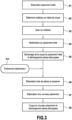
- FIG 5A On the figure 5A is shown a placement of parts P being cut by a cutting system such as that described in connection with the figure 2 .
- the acquisition module 6 (or the operator) detects a defect on the material spread on the cutting table at a defect zone 16.
- This defect zone 16 is located on the location of a Pz part to cut.
- the cutting process according to the invention will directly develop a new placement by specifying that no part must be placed on this defective zone 16.
- the fault zone 16 is described to the automatic placement module in order to be excluded from the new placement.
- the new placement is developed by taking into account the position of the parts to be kept Pc and calculates new positions for all or part of the other parts (parts to be repositioned).
- the part Pz which was previously located on the fault zone 16 is in particular one of these parts to be repositioned.
- the new placement is also developed to optimize the use of material while avoiding producing parts in the defective area.
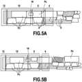
- the defect is not detected when cutting the parts but when they are unloaded by the operator at the unloading module 12 of the cutting system.
- the part Pv having a defect 18 was thus identified by the operator during its unloading.
- the known solution consisted of cutting this defective part by developing an additional placement containing only this part, this additional placement being cut at the end of the current placement (with the consequence of significant losses of material).
- the method according to the invention provides for establishing a list of parts to be kept, then establishing a new placement including in particular the part P'v to be cut.
- the new placement is developed in order to optimize the use of the material by taking into account the position of the parts to be kept and calculates new positions for all or part of the other parts (parts to be repositioned).
- the defective part P'v which must be recut is in particular one of these parts to be repositioned.
- the new placement developed according to the invention includes not only the defective part P'v, but also all the parts belonging to the current placement Qc.
- the pieces to keep are the pieces for which the position in the new placement will not be modified.
- the parts to be repositioned are the parts whose position will be automatically recalculated for the new placement.
- FIG. 8A represents an example of initial placement during cutting with the different modules of the cutting system arranged from upstream to downstream in the direction of advance F of the material: supply module 4, acquisition module 6, cutting module 10 and unloading module 12.
- the trigger event Evt is constituted by the detection of the end of the current roller Rc on which the material spread on the cutting table is conditioned.
- the invention provides for determining the number of parts belonging to the “parts to be kept” group based on an evaluation of their cutting time and the time allocated to calculating the new placement.
- the remaining cutting time that is to say the sum of the cutting times of all the preserved parts. If no parts are present in the “keep” group or they are all already cut, the remaining cutting time is zero. In this case, the cutting will stop while the new placement is received.
- the time for developing the new placement can be limited to a time given by the software.
- This search for parts is advantageously carried out by favoring the parts closest to the unloading module 12. This arbitrary choice makes it possible to maintain the fluidity of the process by offering the operator parts to unload.
- the centerpiece gives indications of its positioning to the daughter piece so that it is positioned correctly. A daughter piece cannot therefore be positioned if its centerpiece has not been positioned. This explains that a daughter piece cannot be assigned to the “to keep” group if, on the other hand, its center piece has been placed in the “to be repositioned” group.
- these parts also form a fixed and indivisible block of parts, so that these parts will either all be assigned to the “keep” group on the current roll, or all assigned to the “reposition” group and placed on the roll following, maintaining their relative positioning.
- this constraint is not always respected. This is particularly the case when a part of the group is already cut and must be kept while another part must necessarily be repositioned.
- the time to develop the new placement is limited by the remaining cutting time.
- the treatment can be interrupted if a certain efficiency value is reached.
- the system can therefore configure the development of the new automatic placement by giving a maximum calculation time and a target efficiency.
- the maximum Max(i) is calculated, and for each part to be repositioned Pr(j), the minimum Min(j) is calculated.
- the limitation Xmin will be equal to the largest of Max(i) less than all of Min(j). The cutting module must guarantee that this placement position will not be evacuated from the cutting zone.
- the feeds of the conveyor must be limited to the same value as the position Xmin of the placement of the authorized parts.
- FIGS 9A to 9C represent the different stages of an example of implementation of the characteristics of the new placement according to the method of the invention.
- the case of placement on patterned material adds the constraints of connections between parts.
- a daughter piece can be separated from its center piece. Additionally, even if the daughter piece and the center piece belong to the “to be repositioned” group, there is no guarantee that the two pieces can be positioned on the same placement.
- the final position of the centerpiece may not be known at the time of this transformation.
- an extrapolation of the real position of the part will be made according to the length of the real step.
- a grid real theoretical will be constructed from the theoretical grid but taking as step length the step which is actually measured at the time of cutting (the average value of the last two lines).
- the pattern point created will be calculated from the intersection (projection on each axis) of the attachment points from the extrapolated position of the key pieces.
- a parameter in the automatic placement module guarantees that a part will only be positioned in a new placement if all its key parts are already there.
- the objective of the new placement is to respond to a problem requiring a modification of the initial placement with as little impact as possible on productivity.
- the calculation time of the new placement will be masked by the cutting of parts which have been kept in their initial position. This therefore implies that the time allocated for completing the new placement is fixed.
- the calculation time will be short because the problem to be solved requires great reactivity. This is the case, for example, of defect detection when the area of material that cannot be used is known shortly before the parts on it are cut. Thus, few pieces can be allocated to the “to keep” group, and therefore the placement time will be short.
- a second optimization phase can be applied. It will work in a similar way to the first (keep parts to be cut to hide the calculation time and replace the others). This time, a larger number of pieces will be kept in order to allow the automatic placement module to develop a second placement but with a greater calculation time. The pieces of this second result (better than the first) can be integrated into the placement during cutting without interruption.
Landscapes
- Engineering & Computer Science (AREA)
- Business, Economics & Management (AREA)
- Life Sciences & Earth Sciences (AREA)
- Mechanical Engineering (AREA)
- Forests & Forestry (AREA)
- Human Resources & Organizations (AREA)
- Economics (AREA)
- Strategic Management (AREA)
- Marketing (AREA)
- General Physics & Mathematics (AREA)
- Theoretical Computer Science (AREA)
- Tourism & Hospitality (AREA)
- Physics & Mathematics (AREA)
- General Business, Economics & Management (AREA)
- Entrepreneurship & Innovation (AREA)
- General Health & Medical Sciences (AREA)
- Operations Research (AREA)
- Game Theory and Decision Science (AREA)
- Development Economics (AREA)
- Manufacturing & Machinery (AREA)
- Health & Medical Sciences (AREA)
- Quality & Reliability (AREA)
- Primary Health Care (AREA)
- Treatment Of Fiber Materials (AREA)
- Auxiliary Devices For And Details Of Packaging Control (AREA)
- Replacement Of Web Rolls (AREA)
- Stacking Of Articles And Auxiliary Devices (AREA)
- Management, Administration, Business Operations System, And Electronic Commerce (AREA)
Priority Applications (3)
| Application Number | Priority Date | Filing Date | Title |
|---|---|---|---|
| SI202130148T SI4139859T1 (sl) | 2020-06-29 | 2021-06-24 | Metoda in sistem za avtomatsko rezanje delov v fleksibilnem materialu, ki je pakiran v obliki zvitka |
| HRP20240671TT HRP20240671T1 (hr) | 2020-06-29 | 2021-06-24 | Postupak i sustav za automatsko krojenje dijelova od fleksibilnog materijala upakiranog u obliku role |
| RS20240559A RS65525B1 (sr) | 2020-06-29 | 2021-06-24 | Postupak i sistem za automatsko krojenje delova od fleksibilnog materijala upakovanog u obliku rolne |
Applications Claiming Priority (2)
| Application Number | Priority Date | Filing Date | Title |
|---|---|---|---|
| FR2006825A FR3111835B1 (fr) | 2020-06-29 | 2020-06-29 | Procédé et système pour la coupe automatique de pièces dans un matériau souple conditionné sous forme de rouleau |
| PCT/FR2021/051159 WO2022003277A1 (fr) | 2020-06-29 | 2021-06-24 | Procédé et système pour la coupe automatique de pièces dans un matériau souple conditionné sous forme de rouleau |
Publications (2)
| Publication Number | Publication Date |
|---|---|
| EP4139859A1 EP4139859A1 (fr) | 2023-03-01 |
| EP4139859B1 true EP4139859B1 (fr) | 2024-02-21 |
Family
ID=72709567
Family Applications (1)
| Application Number | Title | Priority Date | Filing Date |
|---|---|---|---|
| EP21742455.5A Active EP4139859B1 (fr) | 2020-06-29 | 2021-06-24 | Procédé et système pour la coupe automatique de pièces dans un matériau souple conditionné sous forme de rouleau |
Country Status (16)
| Country | Link |
|---|---|
| US (1) | US20230330880A1 (sr) |
| EP (1) | EP4139859B1 (sr) |
| CN (1) | CN115699043A (sr) |
| BR (1) | BR112022025153A2 (sr) |
| ES (1) | ES2987658T3 (sr) |
| FI (1) | FI4139859T3 (sr) |
| FR (1) | FR3111835B1 (sr) |
| HR (1) | HRP20240671T1 (sr) |
| HU (1) | HUE066422T2 (sr) |
| LT (1) | LT4139859T (sr) |
| MX (1) | MX2022015187A (sr) |
| PL (1) | PL4139859T3 (sr) |
| PT (1) | PT4139859T (sr) |
| RS (1) | RS65525B1 (sr) |
| SI (1) | SI4139859T1 (sr) |
| WO (1) | WO2022003277A1 (sr) |
Families Citing this family (3)
| Publication number | Priority date | Publication date | Assignee | Title |
|---|---|---|---|---|
| JP7240059B1 (ja) * | 2022-02-22 | 2023-03-15 | Synflux株式会社 | 情報処理システム、情報処理方法及びプログラム |
| FR3152184A1 (fr) * | 2023-08-16 | 2025-02-21 | Reverse Systems | Procede de classification de chutes previsionnelles de matiere dans un procede de fabrication industrielle, systeme associe |
| CN117576976B (zh) * | 2024-01-03 | 2026-03-17 | 中国民用航空飞行学院 | 一种基于增强现实的通航维修培训系统及方法 |
Family Cites Families (4)
| Publication number | Priority date | Publication date | Assignee | Title |
|---|---|---|---|---|
| FR2731595B1 (fr) | 1995-03-17 | 1997-06-06 | Lectra Systemes Sa | Procede pour la coupe automatique de pieces dans un tissu a motif |
| AT405497B (de) * | 1996-04-02 | 1999-08-25 | Gfm Gmbh | Verfahren zum ausschneiden von zuschnitten aus flachen, unregelmässigen werkstücken, insbesondere lederstücken |
| US10642551B2 (en) * | 2017-07-14 | 2020-05-05 | Georgia-Pacific Corrugated Llc | Engine for generating control plans for digital pre-print paper, sheet, and box manufacturing systems |
| DE102018001175A1 (de) * | 2018-02-15 | 2019-08-22 | Capex Invest GmbH | Verfahren und Vorrichtung zur Unterstützung oder Durchführung eines Schneidprozesses |
-
2020
- 2020-06-29 FR FR2006825A patent/FR3111835B1/fr active Active
-
2021
- 2021-06-24 HR HRP20240671TT patent/HRP20240671T1/hr unknown
- 2021-06-24 RS RS20240559A patent/RS65525B1/sr unknown
- 2021-06-24 ES ES21742455T patent/ES2987658T3/es active Active
- 2021-06-24 MX MX2022015187A patent/MX2022015187A/es unknown
- 2021-06-24 BR BR112022025153A patent/BR112022025153A2/pt unknown
- 2021-06-24 US US18/011,763 patent/US20230330880A1/en active Pending
- 2021-06-24 FI FIEP21742455.5T patent/FI4139859T3/fi active
- 2021-06-24 HU HUE21742455A patent/HUE066422T2/hu unknown
- 2021-06-24 LT LTEPPCT/FR2021/051159T patent/LT4139859T/lt unknown
- 2021-06-24 SI SI202130148T patent/SI4139859T1/sl unknown
- 2021-06-24 EP EP21742455.5A patent/EP4139859B1/fr active Active
- 2021-06-24 PL PL21742455.5T patent/PL4139859T3/pl unknown
- 2021-06-24 WO PCT/FR2021/051159 patent/WO2022003277A1/fr not_active Ceased
- 2021-06-24 CN CN202180041751.6A patent/CN115699043A/zh active Pending
- 2021-06-24 PT PT217424555T patent/PT4139859T/pt unknown
Also Published As
| Publication number | Publication date |
|---|---|
| WO2022003277A1 (fr) | 2022-01-06 |
| HUE066422T2 (hu) | 2024-08-28 |
| PL4139859T3 (pl) | 2024-06-24 |
| SI4139859T1 (sl) | 2024-06-28 |
| ES2987658T3 (es) | 2024-11-15 |
| FR3111835B1 (fr) | 2022-10-14 |
| US20230330880A1 (en) | 2023-10-19 |
| MX2022015187A (es) | 2023-01-16 |
| PT4139859T (pt) | 2024-05-20 |
| FI4139859T3 (fi) | 2024-05-16 |
| HRP20240671T1 (hr) | 2024-08-16 |
| CN115699043A (zh) | 2023-02-03 |
| RS65525B1 (sr) | 2024-06-28 |
| EP4139859A1 (fr) | 2023-03-01 |
| LT4139859T (lt) | 2024-07-25 |
| BR112022025153A2 (pt) | 2023-01-17 |
| FR3111835A1 (fr) | 2021-12-31 |
Similar Documents
| Publication | Publication Date | Title |
|---|---|---|
| EP4139859B1 (fr) | Procédé et système pour la coupe automatique de pièces dans un matériau souple conditionné sous forme de rouleau | |
| EP3555821B1 (fr) | Procédé de partitionnement d'un placement prédéterminé de pièces destinées à être découpées dans un matériau souple en feuille | |
| EP1158267B1 (fr) | Mesurer la qualite d'un corps en forme de bande avec un moyen de prise d'images, reduction de cambrage et ondulation, laminage, ebarbage | |
| EP1153747B1 (fr) | Dispositif de gestion des défauts d impression détectés au sein d une machine d impression | |
| WO2014128424A1 (fr) | Procede de decoupe d'un ou plusieurs vitrages | |
| EP0708700B1 (fr) | Procede pour l'execution de traces ou decoupes suivant des trajectoires predeterminees sur un materiau | |
| EP0759708A1 (fr) | Procede pour la coupe automatique de pieces dans un tissu a motif | |
| CH696527A5 (fr) | Procédé de contrôle de la qualité d'éléments plats et dispositif pour la mise en oeuvre de ce procédé. | |
| WO2008104657A2 (fr) | Procede de decoupe de pieces predefinies dans une matiere en plusieurs couches avec controle automatique des dimensions des pieces | |
| EP2782709B1 (fr) | Procédé d'obtention d'une lentille ophtalmique | |
| EP3565909B1 (fr) | Procédé de modification de la trajectoire de coupe de pièces destinées à être découpées dans un matériau souple | |
| EP3659734B1 (fr) | Procédé de détermination d'au moins un paramètre d'usure d'un fil de coupe et son dispositif de mise en oeuvre | |
| EP1704931B2 (fr) | Procédé de traitement d'envois postaux incluant un contrôle de rang | |
| EP2394817A1 (fr) | Procédé de traitement de produits plats et dispositif correspondant | |
| EP3986191B1 (fr) | Procédé de placement de pièces destinées à être découpées de façon automatique dans un tissu à motif | |
| EP4096883A1 (fr) | Procédé et système pour la coupe automatique de pièces à défaut dans un tissu à motif | |
| FR3159030A1 (fr) | Procede de classification de chutes previsionnelles longitudinales de matiere dans un procede de fabrication industrielle, systeme associe | |
| EP2213395B1 (fr) | Procédé de préparation de réglages d'outils, dispositif de préparation de réglages d'outils, et procédé de réglages d'outils | |
| FR3039913A1 (fr) | Procede d'optimisation de la fabrication de persiennes | |
| FR3152184A1 (fr) | Procede de classification de chutes previsionnelles de matiere dans un procede de fabrication industrielle, systeme associe | |
| EP0134366B1 (fr) | Procédé et installation pour le traitement de tôles brutes issues d'un laminoir à produits plats | |
| FR3056428A1 (fr) | Procede de decoupe de tranches dans un lingot en materiau dur | |
| FR2872596A1 (fr) | Procede pour synchroniser une pluralite d'operateurs intervenant sur une chaine d'assemblage |
Legal Events
| Date | Code | Title | Description |
|---|---|---|---|
| REG | Reference to a national code |
Ref country code: HR Ref legal event code: TUEP Ref document number: P20240671T Country of ref document: HR |
|
| STAA | Information on the status of an ep patent application or granted ep patent |
Free format text: STATUS: UNKNOWN |
|
| STAA | Information on the status of an ep patent application or granted ep patent |
Free format text: STATUS: THE INTERNATIONAL PUBLICATION HAS BEEN MADE |
|
| PUAI | Public reference made under article 153(3) epc to a published international application that has entered the european phase |
Free format text: ORIGINAL CODE: 0009012 |
|
| STAA | Information on the status of an ep patent application or granted ep patent |
Free format text: STATUS: REQUEST FOR EXAMINATION WAS MADE |
|
| 17P | Request for examination filed |
Effective date: 20221123 |
|
| AK | Designated contracting states |
Kind code of ref document: A1 Designated state(s): AL AT BE BG CH CY CZ DE DK EE ES FI FR GB GR HR HU IE IS IT LI LT LU LV MC MK MT NL NO PL PT RO RS SE SI SK SM TR |
|
| P01 | Opt-out of the competence of the unified patent court (upc) registered |
Effective date: 20230525 |
|
| GRAP | Despatch of communication of intention to grant a patent |
Free format text: ORIGINAL CODE: EPIDOSNIGR1 |
|
| STAA | Information on the status of an ep patent application or granted ep patent |
Free format text: STATUS: GRANT OF PATENT IS INTENDED |
|
| DAV | Request for validation of the european patent (deleted) | ||
| DAX | Request for extension of the european patent (deleted) | ||
| RIC1 | Information provided on ipc code assigned before grant |
Ipc: B26F 1/38 20060101ALI20230828BHEP Ipc: B26D 5/00 20060101ALI20230828BHEP Ipc: A41H 43/00 20060101ALI20230828BHEP Ipc: G06Q 50/04 20120101ALI20230828BHEP Ipc: G06Q 10/04 20230101AFI20230828BHEP |
|
| INTG | Intention to grant announced |
Effective date: 20230914 |
|
| GRAS | Grant fee paid |
Free format text: ORIGINAL CODE: EPIDOSNIGR3 |
|
| GRAA | (expected) grant |
Free format text: ORIGINAL CODE: 0009210 |
|
| STAA | Information on the status of an ep patent application or granted ep patent |
Free format text: STATUS: THE PATENT HAS BEEN GRANTED |
|
| AK | Designated contracting states |
Kind code of ref document: B1 Designated state(s): AL AT BE BG CH CY CZ DE DK EE ES FI FR GB GR HR HU IE IS IT LI LT LU LV MC MK MT NL NO PL PT RO RS SE SI SK SM TR |
|
| REG | Reference to a national code |
Ref country code: GB Ref legal event code: FG4D Free format text: NOT ENGLISH |
|
| REG | Reference to a national code |
Ref country code: CH Ref legal event code: EP |
|
| REG | Reference to a national code |
Ref country code: IE Ref legal event code: FG4D Free format text: LANGUAGE OF EP DOCUMENT: FRENCH |
|
| REG | Reference to a national code |
Ref country code: DE Ref legal event code: R096 Ref document number: 602021009667 Country of ref document: DE |
|
| REG | Reference to a national code |
Ref country code: FI Ref legal event code: FGE |
|
| REG | Reference to a national code |
Ref country code: PT Ref legal event code: SC4A Ref document number: 4139859 Country of ref document: PT Date of ref document: 20240520 Kind code of ref document: T Free format text: AVAILABILITY OF NATIONAL TRANSLATION Effective date: 20240515 |
|
| REG | Reference to a national code |
Ref country code: LT Ref legal event code: MG9D |
|
| REG | Reference to a national code |
Ref country code: SE Ref legal event code: TRGR |
|
| REG | Reference to a national code |
Ref country code: NL Ref legal event code: FP |
|
| PG25 | Lapsed in a contracting state [announced via postgrant information from national office to epo] |
Ref country code: IS Free format text: LAPSE BECAUSE OF FAILURE TO SUBMIT A TRANSLATION OF THE DESCRIPTION OR TO PAY THE FEE WITHIN THE PRESCRIBED TIME-LIMIT Effective date: 20240621 |
|
| PG25 | Lapsed in a contracting state [announced via postgrant information from national office to epo] |
Ref country code: GR Free format text: LAPSE BECAUSE OF FAILURE TO SUBMIT A TRANSLATION OF THE DESCRIPTION OR TO PAY THE FEE WITHIN THE PRESCRIBED TIME-LIMIT Effective date: 20240522 |
|
| PG25 | Lapsed in a contracting state [announced via postgrant information from national office to epo] |
Ref country code: IS Free format text: LAPSE BECAUSE OF FAILURE TO SUBMIT A TRANSLATION OF THE DESCRIPTION OR TO PAY THE FEE WITHIN THE PRESCRIBED TIME-LIMIT Effective date: 20240621 Ref country code: GR Free format text: LAPSE BECAUSE OF FAILURE TO SUBMIT A TRANSLATION OF THE DESCRIPTION OR TO PAY THE FEE WITHIN THE PRESCRIBED TIME-LIMIT Effective date: 20240522 |
|
| REG | Reference to a national code |
Ref country code: HR Ref legal event code: ODRP Ref document number: P20240671T Country of ref document: HR Payment date: 20240603 Year of fee payment: 4 |
|
| REG | Reference to a national code |
Ref country code: EE Ref legal event code: FG4A Ref document number: E024324 Country of ref document: EE Effective date: 20240517 |
|
| REG | Reference to a national code |
Ref country code: HR Ref legal event code: T1PR Ref document number: P20240671 Country of ref document: HR |
|
| REG | Reference to a national code |
Ref country code: HU Ref legal event code: AG4A Ref document number: E066422 Country of ref document: HU |
|
| PG25 | Lapsed in a contracting state [announced via postgrant information from national office to epo] |
Ref country code: DK Free format text: LAPSE BECAUSE OF FAILURE TO SUBMIT A TRANSLATION OF THE DESCRIPTION OR TO PAY THE FEE WITHIN THE PRESCRIBED TIME-LIMIT Effective date: 20240221 |
|
| PG25 | Lapsed in a contracting state [announced via postgrant information from national office to epo] |
Ref country code: SM Free format text: LAPSE BECAUSE OF FAILURE TO SUBMIT A TRANSLATION OF THE DESCRIPTION OR TO PAY THE FEE WITHIN THE PRESCRIBED TIME-LIMIT Effective date: 20240221 |
|
| PG25 | Lapsed in a contracting state [announced via postgrant information from national office to epo] |
Ref country code: SM Free format text: LAPSE BECAUSE OF FAILURE TO SUBMIT A TRANSLATION OF THE DESCRIPTION OR TO PAY THE FEE WITHIN THE PRESCRIBED TIME-LIMIT Effective date: 20240221 Ref country code: DK Free format text: LAPSE BECAUSE OF FAILURE TO SUBMIT A TRANSLATION OF THE DESCRIPTION OR TO PAY THE FEE WITHIN THE PRESCRIBED TIME-LIMIT Effective date: 20240221 |
|
| REG | Reference to a national code |
Ref country code: ES Ref legal event code: FG2A Ref document number: 2987658 Country of ref document: ES Kind code of ref document: T3 Effective date: 20241115 |
|
| REG | Reference to a national code |
Ref country code: DE Ref legal event code: R097 Ref document number: 602021009667 Country of ref document: DE |
|
| PLBE | No opposition filed within time limit |
Free format text: ORIGINAL CODE: 0009261 |
|
| STAA | Information on the status of an ep patent application or granted ep patent |
Free format text: STATUS: NO OPPOSITION FILED WITHIN TIME LIMIT |
|
| PG25 | Lapsed in a contracting state [announced via postgrant information from national office to epo] |
Ref country code: LV Free format text: LAPSE BECAUSE OF NON-PAYMENT OF DUE FEES Effective date: 20240624 |
|
| 26N | No opposition filed |
Effective date: 20241122 |
|
| PG25 | Lapsed in a contracting state [announced via postgrant information from national office to epo] |
Ref country code: LV Free format text: LAPSE BECAUSE OF NON-PAYMENT OF DUE FEES Effective date: 20240624 |
|
| PG25 | Lapsed in a contracting state [announced via postgrant information from national office to epo] |
Ref country code: LU Free format text: LAPSE BECAUSE OF NON-PAYMENT OF DUE FEES Effective date: 20240624 |
|
| PGFP | Annual fee paid to national office [announced via postgrant information from national office to epo] |
Ref country code: NL Payment date: 20250520 Year of fee payment: 5 |
|
| REG | Reference to a national code |
Ref country code: HR Ref legal event code: ODRP Ref document number: P20240671 Country of ref document: HR Payment date: 20250612 Year of fee payment: 5 |
|
| PGFP | Annual fee paid to national office [announced via postgrant information from national office to epo] |
Ref country code: MC Payment date: 20250526 Year of fee payment: 5 |
|
| PGFP | Annual fee paid to national office [announced via postgrant information from national office to epo] |
Ref country code: FI Payment date: 20250520 Year of fee payment: 5 |
|
| PGFP | Annual fee paid to national office [announced via postgrant information from national office to epo] |
Ref country code: PL Payment date: 20250523 Year of fee payment: 5 Ref country code: DE Payment date: 20250520 Year of fee payment: 5 |
|
| PGFP | Annual fee paid to national office [announced via postgrant information from national office to epo] |
Ref country code: GB Payment date: 20250520 Year of fee payment: 5 |
|
| PGFP | Annual fee paid to national office [announced via postgrant information from national office to epo] |
Ref country code: LT Payment date: 20250520 Year of fee payment: 5 |
|
| PGFP | Annual fee paid to national office [announced via postgrant information from national office to epo] |
Ref country code: RS Payment date: 20250623 Year of fee payment: 5 Ref country code: NO Payment date: 20250522 Year of fee payment: 5 |
|
| PGFP | Annual fee paid to national office [announced via postgrant information from national office to epo] |
Ref country code: AL Payment date: 20250624 Year of fee payment: 5 Ref country code: IT Payment date: 20250520 Year of fee payment: 5 Ref country code: BE Payment date: 20250520 Year of fee payment: 5 |
|
| PGFP | Annual fee paid to national office [announced via postgrant information from national office to epo] |
Ref country code: HR Payment date: 20250612 Year of fee payment: 5 |
|
| PGFP | Annual fee paid to national office [announced via postgrant information from national office to epo] |
Ref country code: PT Payment date: 20250522 Year of fee payment: 5 |
|
| PGFP | Annual fee paid to national office [announced via postgrant information from national office to epo] |
Ref country code: HU Payment date: 20250613 Year of fee payment: 5 Ref country code: EE Payment date: 20250606 Year of fee payment: 5 Ref country code: FR Payment date: 20250520 Year of fee payment: 5 |
|
| PGFP | Annual fee paid to national office [announced via postgrant information from national office to epo] |
Ref country code: BG Payment date: 20250527 Year of fee payment: 5 |
|
| PGFP | Annual fee paid to national office [announced via postgrant information from national office to epo] |
Ref country code: AT Payment date: 20250721 Year of fee payment: 5 Ref country code: RO Payment date: 20250616 Year of fee payment: 5 |
|
| PGFP | Annual fee paid to national office [announced via postgrant information from national office to epo] |
Ref country code: TR Payment date: 20250529 Year of fee payment: 5 Ref country code: SK Payment date: 20250526 Year of fee payment: 5 |
|
| PGFP | Annual fee paid to national office [announced via postgrant information from national office to epo] |
Ref country code: CZ Payment date: 20250529 Year of fee payment: 5 |
|
| PGFP | Annual fee paid to national office [announced via postgrant information from national office to epo] |
Ref country code: IE Payment date: 20250522 Year of fee payment: 5 |
|
| PGFP | Annual fee paid to national office [announced via postgrant information from national office to epo] |
Ref country code: SE Payment date: 20250520 Year of fee payment: 5 Ref country code: SI Payment date: 20250527 Year of fee payment: 5 |
|
| PGFP | Annual fee paid to national office [announced via postgrant information from national office to epo] |
Ref country code: ES Payment date: 20250701 Year of fee payment: 5 |
|
| PGFP | Annual fee paid to national office [announced via postgrant information from national office to epo] |
Ref country code: CH Payment date: 20250701 Year of fee payment: 5 |
|
| PG25 | Lapsed in a contracting state [announced via postgrant information from national office to epo] |
Ref country code: CY Free format text: LAPSE BECAUSE OF FAILURE TO SUBMIT A TRANSLATION OF THE DESCRIPTION OR TO PAY THE FEE WITHIN THE PRESCRIBED TIME-LIMIT; INVALID AB INITIO Effective date: 20210624 |