EP4139942B1 - Verfahren zum einbau eines verlängerungsrohrs in einen kernreaktor - Google Patents
Verfahren zum einbau eines verlängerungsrohrs in einen kernreaktor Download PDFInfo
- Publication number
- EP4139942B1 EP4139942B1 EP21749741.1A EP21749741A EP4139942B1 EP 4139942 B1 EP4139942 B1 EP 4139942B1 EP 21749741 A EP21749741 A EP 21749741A EP 4139942 B1 EP4139942 B1 EP 4139942B1
- Authority
- EP
- European Patent Office
- Prior art keywords
- threaded
- extension tube
- crdm
- compressible
- housing
- Prior art date
- Legal status (The legal status is an assumption and is not a legal conclusion. Google has not performed a legal analysis and makes no representation as to the accuracy of the status listed.)
- Active
Links
Images













Classifications
-
- G—PHYSICS
- G21—NUCLEAR PHYSICS; NUCLEAR ENGINEERING
- G21C—NUCLEAR REACTORS
- G21C7/00—Control of nuclear reaction
- G21C7/06—Control of nuclear reaction by application of neutron-absorbing material, i.e. material with absorption cross-section very much in excess of reflection cross-section
- G21C7/08—Control of nuclear reaction by application of neutron-absorbing material, i.e. material with absorption cross-section very much in excess of reflection cross-section by displacement of solid control elements, e.g. control rods
- G21C7/12—Means for moving control elements to desired position
-
- G—PHYSICS
- G21—NUCLEAR PHYSICS; NUCLEAR ENGINEERING
- G21C—NUCLEAR REACTORS
- G21C13/00—Pressure vessels; Containment vessels; Containment in general
- G21C13/02—Details
- G21C13/032—Joints between tubes and vessel walls, e.g. taking into account thermal stresses
- G21C13/036—Joints between tubes and vessel walls, e.g. taking into account thermal stresses the tube passing through the vessel wall, i.e. continuing on both sides of the wall
-
- G—PHYSICS
- G21—NUCLEAR PHYSICS; NUCLEAR ENGINEERING
- G21C—NUCLEAR REACTORS
- G21C13/00—Pressure vessels; Containment vessels; Containment in general
- G21C13/02—Details
- G21C13/06—Sealing-plugs
- G21C13/067—Sealing-plugs for tubes, e.g. standpipes; Locking devices for plugs
-
- G—PHYSICS
- G21—NUCLEAR PHYSICS; NUCLEAR ENGINEERING
- G21C—NUCLEAR REACTORS
- G21C17/00—Monitoring; Testing ; Maintaining
- G21C17/017—Inspection or maintenance of pipe-lines or tubes in nuclear installations
-
- G—PHYSICS
- G21—NUCLEAR PHYSICS; NUCLEAR ENGINEERING
- G21C—NUCLEAR REACTORS
- G21C19/00—Arrangements for treating, for handling, or for facilitating the handling of, fuel or other materials which are used within the reactor, e.g. within its pressure vessel
- G21C19/20—Arrangements for introducing objects into the pressure vessel; Arrangements for handling objects within the pressure vessel; Arrangements for removing objects from the pressure vessel
-
- G—PHYSICS
- G21—NUCLEAR PHYSICS; NUCLEAR ENGINEERING
- G21C—NUCLEAR REACTORS
- G21C3/00—Reactor fuel elements and their assemblies; Selection of substances for use as reactor fuel elements
- G21C3/30—Assemblies of a number of fuel elements in the form of a rigid unit
- G21C3/32—Bundles of parallel pin-, rod-, or tube-shaped fuel elements
- G21C3/326—Bundles of parallel pin-, rod-, or tube-shaped fuel elements comprising fuel elements of different composition; comprising, in addition to the fuel elements, other pin-, rod-, or tube-shaped elements, e.g. control rods, grid support rods, fertile rods, poison rods or dummy rods
-
- G—PHYSICS
- G21—NUCLEAR PHYSICS; NUCLEAR ENGINEERING
- G21C—NUCLEAR REACTORS
- G21C7/00—Control of nuclear reaction
- G21C7/06—Control of nuclear reaction by application of neutron-absorbing material, i.e. material with absorption cross-section very much in excess of reflection cross-section
- G21C7/08—Control of nuclear reaction by application of neutron-absorbing material, i.e. material with absorption cross-section very much in excess of reflection cross-section by displacement of solid control elements, e.g. control rods
- G21C7/10—Construction of control elements
-
- Y—GENERAL TAGGING OF NEW TECHNOLOGICAL DEVELOPMENTS; GENERAL TAGGING OF CROSS-SECTIONAL TECHNOLOGIES SPANNING OVER SEVERAL SECTIONS OF THE IPC; TECHNICAL SUBJECTS COVERED BY FORMER USPC CROSS-REFERENCE ART COLLECTIONS [XRACs] AND DIGESTS
- Y02—TECHNOLOGIES OR APPLICATIONS FOR MITIGATION OR ADAPTATION AGAINST CLIMATE CHANGE
- Y02E—REDUCTION OF GREENHOUSE GAS [GHG] EMISSIONS, RELATED TO ENERGY GENERATION, TRANSMISSION OR DISTRIBUTION
- Y02E30/00—Energy generation of nuclear origin
- Y02E30/30—Nuclear fission reactors
Definitions
- thermal sleeves serve four purposes.
- the thermal sleeve protects the rod cluster control assembly (RCCA) drive rod from the fluid effects present in the reactor vessel head plenum (e.g., cross flow).
- the thermal sleeve facilitates hydraulic communication (flow to the CRDM) during RCCA insertion (control rod drop).
- the thermal sleeve provides alignment to the control drive rod for vessel head installation.
- the thermal sleeve also protects the head penetration and CRDM housing from thermal transients of the reactor coolant.
- Thermal sleeves include an outside diameter (OD) and an inside diameter (ID) and include flanges. Thermal sleeves are subject to wear at the flanges and the OD / ID. It has been observed that thermal sleeves are subject to wear between the upper head and the CRDM penetration housing in a nuclear reactor. This wear has been measured using laser metrology to determine the amount that a particular thermal sleeve has "dropped.”
- Thermal sleeve flange and OD / ID wear results in recurring maintenance costs. Thermal sleeve failure due to OD / ID wear requires costly repair before a return to power is possible. Wear predictions through Pressurized Water Reactor Owners Group (PWROG) programs can be used to identify which sleeves will need eventual intervention. Proactive elimination of the thermal sleeves can eliminate or greatly delay future thermal sleeve inspections for any type of wear.
- PWROG Pressurized Water Reactor Owners Group
- a method for removing a worn thermal sleeve and replacing it with a temporary "compressible thermal sleeve” has been developed.
- the method does not require removal of the CRDM motor assembly from the top side of the reactor head.
- the method does not address the failure mechanism due to thermal sleeve wear and CRDM penetration housing. Thus, even a compressible thermal sleeve will most likely continue to wear along with the CRDM penetration housing.
- the present disclosure provides a method for installing an extension tube in a nuclear reactor comprising a control rod drive mechanism (CRDM) housing with a threaded head penetration nozzle and a thermal sleeve disposed therein.
- the method comprises removing the thermal sleeve from the threaded head penetration nozzle and aligning the extension tube with a threaded end of the threaded head penetration nozzle.
- the extension tube comprises a threaded end and non-threaded end, the threaded end sized and configured to threadably couple to the threaded head penetration nozzle.
- the method further comprises threading the threaded end of the extension tube to the threaded end of the threaded head penetration nozzle, torqueing the extension tube to the threaded end of the threaded head penetration nozzle, gauging the alignment of the extension tube relative to the threaded head penetration nozzle, installing retention fillet welds between the extension tube and the threaded end of the threaded head penetration nozzle, and installing a guide funnel to the non-threaded end of the extension tube.
- the present disclosure provides a method for installing an extension tube in a nuclear reactor comprising a control rod drive mechanism (CRDM) housing with a non-threaded head penetration nozzle and a thermal sleeve disposed therein.
- the method comprises removing the thermal sleeve from the non-threaded head penetration nozzle, machining the non-threaded head penetration nozzle of the CRDM housing, installing and aligning a threaded adapter to the machined end of the non-threaded head penetration nozzle of the CRDM housing, joining the threaded adapter to the machined end of the non-threaded head penetration nozzle of the CRDM housing, machining a bore defined by the non-threaded head penetration nozzle of the CRDM housing, machining a bore defined by the threaded adapter, machining an outside diameter of a joint between the machined end of the non-threaded head penetration nozzle of the CRDM housing and the threaded adapter, installing the extension tube to the threaded adapter
- related systems include but are not limited to circuitry and/or programming for effecting herein-referenced method aspects; the circuitry and/or programming can be virtually any combination of hardware, software, and/or firmware configured to affect the herein-referenced method aspects depending upon the design choices of the system designer.
- circuitry and/or programming can be virtually any combination of hardware, software, and/or firmware configured to affect the herein-referenced method aspects depending upon the design choices of the system designer.
- the present disclosure is directed, as stated above, to methods for eliminating thermal sleeves in nuclear reactors.
- the present disclosure is directed to methods for replacing the thermal sleeves with extension tubes which attach directly to CRDM penetration housings of the nuclear reactor.
- the thermal sleeve can be removed from underneath the reactor vessel closure head (RVCH) using exiting equipment and processes for thermal sleeve removal.
- An extension tube, which attaches directly to the CRDM penetration housing, is installed.
- Threaded penetrations have a 95.25 mm (3 3/4")-8 UN-2A thread.
- Non-threaded penetrations have a bare tubular end with radii on both the OD and ID to face transitions.
- an extension tube may be manufactured to a specific length which would set a funnel height at the same elevation as existing thermal sleeves when threaded on and tightened.
- a penetration nozzle may be welded on to the penetration which would then provide the proper male thread for attaching the extension tube.
- a special Compressible Guide Sleeve has been designed to provide the same functions that the guide sleeve does on replacement RVCHs and AP1000 pressurized water reactors, for example.
- the CGS can be installed from underneath the RVCH, along with the extension tube.
- the present disclosure provides a new and innovative process of retrofitting an extension tube onto an in-service RVCH.
- Thermal sleeves that exhibit flange and / or ID / OD wear are suitable candidates for elimination and replacement with extension tubes to eliminate recurring maintenance costs and failures which require costly repairs before a return to power is possible. Wear predictions through PWROG programs can be used to identify which thermal sleeves will need eventual intervention. Proactive elimination combined with engineering justification can eliminate or greatly delay future thermal sleeve inspections for a many types of wear.
- FIG. 1 is a schematic cross-sectional view of an upper portion of a conventional nuclear reactor 2 illustrating a portion of a reactor vessel 4 penetrated by a plurality of head penetration nozzles 6 which extend downward from a CRDM housing 8.
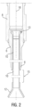
- FIG. 2 is a schematic cross-sectional view of a conventional reactor vessel head penetration illustrating a CRDM housing 8, a head penetration nozzle 6, and a thermal sleeve 10.
- a thermal sleeve 10 including a guide funnel 12 is positioned within each head penetration nozzle 6 beneath each CRDM housing 8 such that each guide funnel 12 is positioned directly above, and spaced a distance from, a corresponding guide tube 14 extending from an upper support plate 16 within reactor vessel 4.
- the thermal sleeve 10 is housed within the head penetration nozzle 6 within the reactor vessel 4 except within region 15 ( FIG. 2 ) where the thermal sleeve 10 is exposed to the reactor coolant.
- the present disclosure provides methods for eliminating thermal sleeves 10 in a nuclear reactor 2 and, more particularly, methods for replacing thermal sleeves 10 in a nuclear reactor 2 with extension tubes attached directly to a CRDM penetration housing 6 of the nuclear reactor 2. These methods squarely fulfill the strong and repeated need for permanent thermal sleeve 10 replacement to remove the need for multiple, varied thermal sleeve 10 inspections over time.
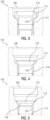
- FIG. 3 is a section view 100 of a thermal sleeve 110 and a CDRM housing 108 in an un-worn condition.
- the thermal sleeve 110 includes a flange 112 defines an outside diameter 114 (OD) and an inside diameter 116 (ID) that are subject to wear.
- the thermal sleeve 110 is subject to wear between the upper head and the CRDM penetration housing 108 in a nuclear reactor.
- FIG. 4 is a section view 120 of the thermal sleeve 110 and the CDRM housing 108 in a substantially worn condition.
- the thermal sleeve 110 shows substantial wear at the flange 112 and the OD 114 and ID 116. This wear my be manifested by a drop of the thermal sleeve 110.
- FIG. 5 is a section view 140 of the thermal sleeve 110 and the CDRM housing in a worn condition to the point of thermal sleeve 110 separation. As shown, the thermal sleeve 110 has developed a crack 118 resulting in the separation of the thermal sleeve 110.
- the section view 140 also shows additional wear of the flange 112, OD 114, and ID 116 relative to the section view 120 shown in FIG. 4 .
- extension tubes can be retrofitted in a variety of reactor vessel 4 ( FIG. 1 ) heads which currently have thermal sleeves 10 ( FIGS. 1-2 ), 110 ( FIGS. 3-5 ) installed.
- Typical CRDM penetration designs have either "threaded” or “non-threaded” ends protruding through the reactor vessel 4 head.
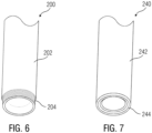
- FIG. 6 an extension tube 200 that can be installed in the nuclear reactor 4 in place of thermal sleeves 10, 110 is shown.
- the extension tube 200 comprises a substantially cylindrical body 202 and a threaded end 204 that would protrude through the reactor vessel 4 head once installed and threadably couple to threaded penetration nozzle.
- the extension tube 240 can be installed in the nuclear reactor 4 in place of thermal sleeves 10, 110.
- the extension tube 240 comprises a substantially cylindrical body 242 and a non-threaded end 244 that would protrude through the reactor vessel 4 head once installed and couple to a non-threaded penetration nozzle by a suitable weld, for example.
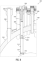
- FIG. 8 is a schematic cross-sectional view of an upper portion of a conventional nuclear reactor 302 illustrating a portion of a reactor vessel head 304 penetrated by a plurality of head penetration nozzles 306 which extend downward from a CRDM housing 308.
- An extension tube 310 is coupled to the distal end 314 of the head penetration nozzle 306.
- the distal end 316 of the extension tube includes a guide funnel 312.
- the head penetration nozzles 306 include a compressible guide sleeve 318.
- a threaded penetration adapter 320 is coupled between the extension tube 310 and the head penetration nozzle 306.
- the threaded penetration adapter 320 is employed for non-threaded penetration nozzles 306 in order to facilitate the installation of the extension tube 310 on a non-threaded head penetration nozzle 306.
- the threaded penetration adapter 320 is welded to the end of the non-threaded head penetration nozzle 306.
- Compressible guide sleeves 318 are further described in commonly owned patent application number PCT/US2019/015797, filed 30 January 2019 , titled THERMAL SLEEVE.
- FIG. 9 is a section view of the threaded penetration adapter 320 coupled between the extension tube 310 and the head penetration nozzle 306.
- the threaded penetration adapter 320 includes a body 322 with an upper end adapted and configured to couple to the non-threaded end of the head penetration nozzle 306 and a lower end adapted and configured to couple to the extension tube 310.
- the upper end of the body 322 of the threaded penetration adapter 320 may be welded to the non-threaded head penetration nozzle 306 at connection 324 and the lower end of the threaded adapter body 322 may be welded to the extension tube 310 at connection 326.
- the connection 326 is a bimetallic weld in the extension tube 310 to transition to steel.
- the threaded penetration adapter 320 may include threads to threadably couple to the non-threaded head penetration nozzle 306 and / or the extension tube 310, for example.
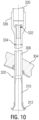
- FIG. 10 is a section view of a head penetration nozzle 306 with the extension tube 310.
- the head penetration nozzle 306 extends downward from a latch housing 336 and penetrates the reactor vessel head 304.
- the latch housing 336 contains a CRDM motor 330 and a compressible guide sleeve 332.
- the latch housing 336 is coupled to the head penetration nozzle 306 via a bimetallic weld 334.
- the head penetration nozzle 306 is coupled to an extension tube 310 within the reactor vessel head 304 through a threaded penetration adapter 320.
- the extension tube 310 is coupled to a guide funnel 312. As shown in FIG. 10 , the thermal sleeve in the head penetration nozzle 306 has been replaced by the extension tube 310.
- FIG. 11 is a section view of the head penetration nozzle 306 located through the reactor vessel head 304.
- the end of the head penetration nozzle outside the reactor vessel head 304 comprises a CRDM head adapter 337.
- the head penetration nozzle 306 defines a space 338, which normally contains a thermal sleeve that is notably missing.
- FIG. 12 is a section view of the head penetration nozzle 306 with the extension tube 310.
- the head penetration nozzle 306 is coupled to the extension tube 310 via an optional threaded penetration adapter 320.
- the compressible guide sleeve 332, shown in detail in FIG. 14 is normally contained within a space 340 defined by the head penetration nozzle 306.
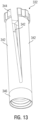
- FIG. 13 is a perspective view of a compressible guide sleeve 332, which is received in the space 340 defined by the head penetration nozzle 306, as shown in FIG. 12 .
- the compressible guide sleeve 332 comprises a three-leaf compressible flex section 342 for compressibility and stiffness.
- the compressible guide sleeve may comprise at least two and more than three compressible sleeves.
- Each of the leaf compressible flex sections 342 includes a flange 344 that is positioned within the CRDM housing 308.
- the compressible guide sleeve 332 is installed into the CRDM penetration to facilitate drive rod guidance into the latch housing 336 ( FIG. 10 ).
- the bottom end of the compressible guide sleeve 332 comprises an alignment feature 346.
- Existing thermal sleeve elimination modifications in new RVCHs employ a smaller guide sleeve similar to a truncated thermal sleeve.
- the purpose of the guide sleeve is to provide guidance for the drive rod into the CRDM latch assembly.
- the compressible guide sleeve 332 accomplishes the same function as the guide sleeve and is installed from underneath the reactor vessel head 304 (FIGS- 8-12), after the extension tube 310 has been attached to the head penetration nozzle 306.
- the compressible guide sleeve 332 allows for it to be flexible enough to be installed through the CRDM penetration, it is also stiff ; rigid enough that it requires a specialized fixture to compress the compressible guide sleeve 332 prior to installation. This stiffness is sufficient for it to remain in place during all of a nuclear plant's design basis conditions.
- the entire extension tube 310 installation process occurs underneath the RVCH and requires no modifications or removals of the CRDM and requires no modifications to the upper internal components. Under-the-head installation processes are known and have been developed by the owner of the present application. The replacement of the thermal sleeve with the entire extension tube 310 eliminates all future thermal sleeve wear at the installation location. The extension tube 310 requires no inspections for wear throughout its life.
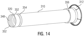
- FIG. 14 illustrates an extension tube 310 with a guide funnel 312 and a threaded penetration adapter 320.
- the guide funnel 312 is collapsible and is configured to fail before CRDM or fuel damage can occur in the event of misalignment during head installation.
- the threaded penetration adapter 320 includes a threaded end with female threads 348 to threadably couple to male threads 349 ( FIG. 17 ) of the head penetration nozzle 306 ( FIGS. 8-13 ).
- retention fillet welds 352 are provided between the threaded penetration adapter 320 and the head penetration nozzle 306 to stabilize the connection.
- the threaded penetration adapter 320 is coupled to the extension tube 310 by a weld 354.
- the extension tube 310 is coupled to the guide funnel 312 by retention fillet welds 356.
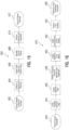
- FIG. 15 is a process 400 for removing a thermal sleeve in need of removal.
- the process 400 will now be described with reference to FIGS. 1-5 and 15 .
- the thermal sleeve 10 ( FIGS. 1-2 ), 110 ( FIGS. 3-5 ) in need of removal is identified 402.
- the ID of the thermal sleeve 10, 110 is flapped and cleaned 404.
- the electrical discharging machining (EDM) head is installed 406 on one section of the thermal sleeve 10, 110 and the a series of cuts is performed. Once the series of cuts is completed, the thermal sleeve 10, 110 is removed 408 and the head penetration nozzle 306 is cleaned and inspected 410.
- the thermal sleeve 10, 110 removal is now complete 412.
- FIG. 16 is a process 440 for installing a threaded extension tube.
- the process 400 will now be described with reference to FIGS. 1-5 , 8-14 , and 16 .
- the threaded extension tube 310 is installed 444.
- the extension tube 310 is torqued 446 to the head penetration nozzle 306 using a torque tool.
- the alignment of the extension tube 310 is gauged 448.
- Retention fillet welds 352 are installed 450.
- a compressible guide sleeve 332 is installed 452 and the alignment of the extension tube 310 is finally gauged 454.
- the installation is now complete and the extension tube 310 is in its final installed arrangement 456. Details of the extension tube installation process 440 will now be described in more detail.
- FIGS. 17 and 18 illustrate the process step of installing 444 the threaded extension tube 310.
- the extension tube 310 comprising a threaded penetration adapter 320 is aligned with a threaded head penetration nozzle 306 extending through the reactor vessel head 304.
- the threaded head penetration nozzle 306 comprises a threaded end 307 with male threads 349 configured to threadably couple the female threads 348 of the threaded end of the threaded penetration adapter 320.
- the threaded penetration adapter 320 is coupled to the extension tube 310 by a weld 354.
- the female threads 348 of the threaded end of the threaded penetration adapter 320 is threadably coupled to the male threads 349 of the threaded end 307 of the threaded head penetration nozzle 306.
- FIGS. 19 and 20 illustrate torqueing 446 the extension tube 310 to the head penetration nozzle 306 using a torque tool 350.
- FIGS. 21-23 illustrates the process of gauging 448 the extension tube 310 alignment after it has been properly torqued 446 to the head penetration nozzle 306,
- FIG. 21 is a section view 520 of an extension tube 310 alignment gauging test
- FIG. 22 is a perspective view of a gauge 522 used in the gauging 448 process
- FIG. 23 is a section view of the alignment of a drive rod 530 relative to the extension tube 310.
- the gauge 522 is inserted into the guide funnel 312, through the extension tube 310, the head penetration nozzle 306, and into the CRDM housing 308.
- the gauge 522 is rotated to fit into the guide funnel 312.
- the alignment of the extension tube 310 is measured relative to a nominal centerline with a maximum offset permitted from the nominal centerline.
- Datum A is measured at a point along the extension tube 310 and at a first radial offset 524 extending radially from the gauge 522 located at the end of the extension tube 310 near the guide tube 312, a second radial offset 526 located within the head penetration nozzle 306 just outside the reactor vessel head 304, and a third radial offset 528 located inside the CRDM housing 308.
- the amount of shift relative to datum A is determined at each radial offset 524, 256, 528 location.
- FIG. 23 the alignment of a drive rod 532 is shown relative to the inlet of the guide funnel 312.
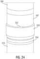
- FIG. 24 illustrates the retention fillet welds 352 installed 450 between the threaded end 307 of the head penetration nozzle 306 and the threaded penetration adapter 320 coupled to the extension tube 310 by a weld 354.
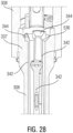
- FIGS. 25-29 illustrate the process of installing 452 the compressible guide sleeve 332.
- the three-leaf compressible flex sections 342 of the compressible guide sleeve 332 are compressed to contract the flanges 344 of the compressible flex sections 342 to a size suitable for introducing into the guide funnel 312.
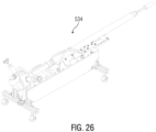
- FIG. 26 illustrates a compression tool 534 that may be employed to compress the compressible guide sleeve 332 prior to inserting the compressible guide sleeve 332 into the guide nozzle 312.
- FIG. 27 illustrates the compressible guide sleeve 332 in its compressed configuration inserted through the head penetration nozzle 306 and the CRDM head adapter 337 such that the flanges 344 of the compressible flex sections 342 are positioned just above a counterbore ledge 536 defined within the CRDM head adapter 337 section of the head penetration nozzle 306.
- the compressible flex sections 342 of the compressible guide sleeve 332 are released such that the flanges 344 of the compressible flex sections 342 engage the counterbore ledge 536 defined within the CRDM head adapter 337 section of the head penetration nozzle 306.
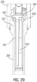
- FIG. 29 illustrates the compressible guide sleeve 332 in its final installed state. A final gauging 454 of the extension tube 310 can now be performed.
- FIGS. 30-33 illustrate the final installed arrangement 456 of the extension tube 310.
- FIG. 30 is a section view of the reactor vessel head 304 illustrating the extension tube 310 coupled to the head penetration nozzle 306 installed inside the reactor vessel head 304.
- FIG. 31 is a detailed view of the installed extension tube 310 coupled to the head penetration nozzle 306 showing the extension tube retention welds 352.
- FIG. 32 is a section view of the extension tube 310 coupled to the head penetration nozzle 306 installed inside the reactor vessel head 304.
- FIG. 33 is an elevation view of the extension tube 310 coupled to the head penetration nozzle 306 installed inside the reactor vessel head 304.
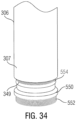
- FIG. 34 illustrates a head penetration nozzle 306 with threads 552 that are not usable, due to wear, damage, or sizing mismatch.
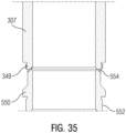
- FIG. 35 is a section view of the head penetration 306 nozzle shown in FIG. 34 .
- a threaded adapter 550 may be employed as a contingency.
- the threaded adapter 550 is welded 554 below the male threads 349 of the head penetration nozzle 310.
- the threaded adapter 550 includes male threads 552 suitable for threadably coupling the female thread 348 on the threaded adapter 320 of the extension tube 310.
- extension tube 310 in the field becomes more complicated at nuclear plants without CRDM housings comprising threaded head penetration nozzles 306. Additional field machining would be required to prepare the non-threaded CRDM housing for welding, as well as perform post-welding cleanup. Design of the extension tube 310 remains common between threaded and non-threaded CRDM housings. A process for installing an extension tube 310 on a non-threaded CRDM housing is described hereinbelow.
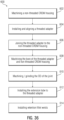
- FIG. 36 is a process 600 for installing an extension tube on a non-threaded CRDM housing.
- the process 600 begins by machining 602 a non-threaded CRDM housing 650.
- the CRDM housing 650 does not include a threaded head penetration nozzle with a threaded end 307 with male threads 349 as described with reference to FIGS. 3-35 .
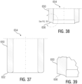
- FIG. 37 is a section view of a non-threaded CRDM housing 650 before machining.
- the machining 602 step involves preparing the face 652 ( FIG.
- FIG. 38 is a section view of the non-threaded CRDM housing 650 after machining 602.
- FIG. 39 is a detail view of the section view of the non-threaded CRDM housing shown in FIG. 38 .
- the face 656 (post-machining) of the non-threaded CRDM housing 650 is machined back to remove the radii and install the prep weld.
- FIG. 39 shows a detailed view of the machined face 656 of the non-threaded CRDM housing 650.
- FIG. 41 illustrates a gap 668 defined between the machined end face 656 of the non-threaded CRDM housing 650 and the non-threaded end 664 of the threaded adapter 660.
- the next step in the process 600 is installing and aligning 604 a threaded adapter 660 to the machined non-threaded CRDM housing 650.
- the threaded adapter 660 comprises male threads 662 sized and configured to receive the female threads 348 of the extension tube 310 (See FIG.
- the threaded adapter 660 also defines a bore 670. As shown in FIG. 41 , a gap 668 is defined between the machined end face 656 of the non-threaded CRDM housing 650 and the non-threaded end of the threaded adapter 660.
- FIG. 42 illustrates the threaded adapter 660 joined to the non-threaded CRDM housing 650.
- the next step in the process 600 is joining 606 the threaded adapter 660 to the non-threaded CRDM housing 650.
- the threaded adapter 660 is joined 606 to the CRDM housing by the a penetration welding technique to form a joint 672.
- the threaded adapter 660 may be joined 606 to the non-threaded CRDM housing 650 by a full penetration weld that joins 606 the threaded adapter 660 to the non-threaded CRDM housing 650 with no gaps in between the filler material and the roots of the joint 672.
- the threaded adapter 660 may be welded to the non-threaded CRDM housing 650 may be performed using a specialized semiautomatic gas tungsten arc welding (GTAW) weld head, for example.
- GTAW semiautomatic gas tungsten arc welding
- FIG. 43 illustrates machined bores 654, 670 defined by the non-threaded CRDM housing and the threaded adapter.
- the next step in the process 600 is machining 608 the bore 670 defined by the threaded adapter 660 and / or the bore 654 defined by the non-threaded CRDM housing 650. This step removes an integral backing ring / alignment ring.
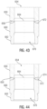
- FIG. 44 illustrates a machined / ground OD 674 of the joint 672.
- the next step in the process 600 is machining / grinding 610 the OD 674 of the joint 672, such as the penetration weld cap, for inspections.
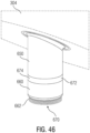
- FIGS. 45 and 46 show the threaded adapter 660 attached to the non-threaded CRDM housing 650 installed below the reactor vessel head 304 and ready to receive the extension tube 310.
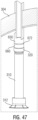
- FIG. 47 illustrates the threaded adapter 320 of the extension tube 310 installed on the threaded adapter attached to the non-threaded CRDM housing from below the reactor vessel head 304.
- the next step in the process 600 is installing the threaded adapter 320 of the extension tube 310 on the threaded adapter 660 attached to the non-threaded CRDM housing from below the reactor vessel head 304.
- This step includes threading and torqueing the extension tube 310 on the threaded adapter 660 in manner similar to that described above wit reference to 17-20.
- FIG. 48 illustrates retention fillet welds 676 between the threaded adapter 320 of the extension tube 310 and the threaded adapter 660 of the non-threaded CRDM housing 650.
- the next step in the process 600 is installing 614 retention fillet welds 676.
- the process 600 may comprise installing a guide funnel 312 as described above with reference to FIGS. 8-14 , for example.
- the process 600 may further comprise gauging the alignment of the extension tube using the same process described above with reference to FIGS. 21-23 , for example.
- the process 600 may further comprise installing a compressible guide sleeve 332 using the same process described above with reference to FIGS. 25-29 , for example.
Landscapes
- Physics & Mathematics (AREA)
- Engineering & Computer Science (AREA)
- Plasma & Fusion (AREA)
- General Engineering & Computer Science (AREA)
- High Energy & Nuclear Physics (AREA)
- Chemical & Material Sciences (AREA)
- Chemical Kinetics & Catalysis (AREA)
- Monitoring And Testing Of Nuclear Reactors (AREA)
- Jet Pumps And Other Pumps (AREA)
- Non-Silver Salt Photosensitive Materials And Non-Silver Salt Photography (AREA)
- Mechanical Coupling Of Light Guides (AREA)
- Valve-Gear Or Valve Arrangements (AREA)
Claims (17)
- Verfahren zum Anbringen eines Verlängerungsrohrs (310) in einem Kernreaktor (2), der ein Steuerstabantriebsmechanismus- (CRDM-) Gehäuse (8) mit einer Gewindekopf-Durchführungsdüse (306) und einerThermohülse (10) darin aufweist, wobei das Verfahren aufweist:Entfernen derThermohülse (10) von der Gewindekopf-Durchführungsdüse (306);Ausrichten des Verlängerungsrohrs (310) mit einem Gewindeende (307) der Gewindekopf-Durchführungsdüse (306), wobei das Verlängerungsrohr ein Gewindeende (348) und ein Nichtgewindeende aufweist, wobei das Gewindeende (348) zum gewindeartigen Koppeln mit der Gewindekopf-Durchführungsdüse (306) bemessen und ausgebildet ist;Anschrauben des Gewindeendes (348) des Verlängerungsrohrs (310) an das Gewindeende (307) der Gewindekopf-Durchführungsdüse (306);Anziehen des Verlängerungsrohrs (310) an dem Gewindeende (307) der Gewindekopf-Durchführungsdüse (306);Messen der Ausrichtung des Verlängerungsrohrs (310) relativ zur Gewindekopf-Durchführungsdüse (306);Anbringen von Rückhaltekehlnähten (352) zwischen dem Verlängerungsrohr (310) und dem Gewindeende (307) der Gewindekopf-Durchführungsdüse (306) undAnbringen eines Führungstrichters (312) an dem Nichtgewindeende des Verlängerungsrohrs (310).
- Verfahren nach Anspruch 1, das ein Anbringen einer komprimierbaren Führungshülse (332) an dem CRDM-Gehäuse (8) aufweist.
- Verfahren nach Anspruch 2, wobei das Anbringen der komprimierbaren Führungshülse (332) an dem CRDM-Gehäuse (8) aufweist:Komprimieren der komprimierbaren Führungshülse (332);Einführen der komprimierten komprimierbaren Führungshülse (332) in den Führungstrichter, durch das Verlängerungsrohr, die Gewindekopf-Durchführungsdüse (306) und das CRDM-Gehäuse (8) undFreigeben der Komprimierung der komprimierbaren Führungshülse (332), um die komprimierbare Führungshülse rückhaltend mit dem CRDM-Gehäuse zu verbinden.
- Verfahren nach Anspruch 3, wobei die komprimierbare Führungshülse (332) mehrere komprimierbare Blatt-Biegeabschnitte (342) aufweist, wobei jeder der mehreren komprimierbaren Blatt-Biegeabschnitte einen Flansch (344) aufweist, wobei das Verfahren aufweist:Komprimieren der mehreren komprimierbaren Blatt-Biegeabschnitte, um die Flansche vor dem Einführen der komprimierten Führungshülse in den Führungstrichter zusammenzuziehen; undFreigeben der Komprimierung der komprimierbaren Führungshülse nach dem Einführen in das CRDM-Gehäuse, um die Flansche dazu freizugeben, mit einem durch das CRDM-Gehäuse definierten Senkungsabsatz (536) zusammenzugreifen.
- Verfahren zum Anbringen eines Verlängerungsrohrs (310) in einem Kernreaktor (2), der ein Steuerstabantriebsmechanismus- (CRDM-) Gehäuse (650) mit einer Nichtgewindekopf-Durchführungsdüse und einer Thermohülse (10) darin aufweist, wobei das Verfahren aufweist:Entfernen der Thermohülse (10) von der Nichtgewindekopf-Durchführungsdüse;Bearbeiten der Nichtgewindekopf-Durchführungsdüse des CRDM-Gehäuses (650);Anbringen und Ausrichten eines Gewindeadapters (660) an dem bearbeiteten Ende der Nichtgewindekopf-Durchführungsdüse des CRDM-Gehäuses (650);Zusammenfügen des Gewindeadapters (660) mit dem bearbeiteten Ende der Nichtgewindekopf-Durchführungsdüse des CRDM-Gehäuses (650);Bearbeiten einer durch die Nichtgewindekopf-Durchführungsdüse des CRDM-Gehäuses (650) definierten Bohrung (654);Bearbeiten einer durch den Gewindeadapter (660) definierten Bohrung (670);Bearbeiten eines Außendurchmessers einer Verbindung (672) zwischen dem bearbeiteten Ende der Nichtgewindekopf-Durchführungsdüse des CRDM-Gehäuses (650) und dem Gewindeadapter (660);Anbringen des Verlängerungsrohrs (310) an dem Gewindeadapter (660) undAnbringen von Rückhaltekehlnähten (676) zwischen dem Verlängerungsrohr (310) und dem Gewindeadapter (660).
- Verfahren nach Anspruch 5, wobei das Bearbeiten der Nichtgewindekopf-Durchführungsdüse des CRDM-Gehäuses (650) aufweist:Vorbereiten einer Fläche (656) der Nichtgewindekopf-Durchführungsdüse des CRDM-Gehäuses (650) undZurückdrehen eines Innendurchmessers der durch die Nichtgewindekopf-Durchführungsdüse des CRDM-Gehäuses (650) definierten Bohrung (654).
- Verfahren nach Anspruch 5, wobei das Zusammenfügen des Gewindeadapters mit dem bearbeiteten Ende der Nichtgewindekopf-Durchführungsdüse des CRDM-Gehäuses (650) ein Durchführen einer Durchbruchschweißtechnik zum Bilden der Verbindung (672) aufweist.
- Verfahren nach Anspruch 7, wobei das Zusammenfügen des Gewindeadapters (660) mit dem bearbeiteten Ende der Nichtgewindekopf-Durchführungsdüse des CRDM-Gehäuses (650) ein Durchführen einer Durchbruchschweißtechnik zum Bilden der Verbindung (672) aufweist.
- Verfahren nach Anspruch 5, wobei das Anbringen des Verlängerungsrohrs (310) an dem Gewindeadapter (660) aufweist:Anschrauben des Verlängerungsrohrs (310) an den Gewindeadapter (660) undAnziehen des Verlängerungsrohrs (310) an dem Gewindeadapter (660).
- Verfahren nach Anspruch 5, das ein Messen einer Ausrichtung des Verlängerungsrohrs (310) relativ zur Nichtgewindekopf-Durchführungsdüse (650) aufweist.
- Verfahren nach Anspruch 5, das ein Anbringen eines Führungstrichters (312) an einem Nichtgewindeende des Verlängerungsrohrs (310) aufweist.
- Verfahren nach Anspruch 11, das ein Anbringen einer komprimierbaren Führungshülse (332) an dem CRDM-Gehäuse (650) aufweist.
- Verfahren nach Anspruch 12, wobei das Anbringen der komprimierbaren Führungshülse (332) an dem CRDM-Gehäuse (650) aufweist:Komprimieren der komprimierbaren Führungshülse (332);Einführen der komprimierten komprimierbaren Führungshülse (332) durch das Verlängerungsrohr (310), die Nichtgewindekopf-Durchführungsdüse und das CRDM-Gehäuse (650) undFreigeben der Komprimierung der komprimierbaren Führungshülse (332), um die komprimierbare Führungshülse (332) rückhaltend mit dem CRDM-Gehäuse (650) zu verbinden.
- Verfahren nach Anspruch 13, wobei die komprimierbare Führungshülse (332) mehrere komprimierbare Blatt-Biegeabschnitte (342) aufweist, wobei jeder der mehreren komprimierbaren Blatt-Biegeabschnitte einen Flansch (344) aufweist, wobei das Verfahren aufweist:Komprimieren der mehreren komprimierbaren Blatt-Biegeabschnitte, um die Flansche vor dem Einführen der komprimierten komprimierbaren Führungshülse (332) in das Verlängerungsrohr (320) zusammenzuziehen; undFreigeben der Komprimierung der komprimierbaren Führungshülse (332) nach dem Einführen in das CRDM-Gehäuse (650), um die Flansche zum Zusammengreifen mit einem durch das CRDM-Gehäuse (650) definierten Senkungsabsatz (536) freizugeben.
- Verfahren nach einem der Ansprüche 4 oder 14, das ein Durchführen einer Abschlussmessung einer Ausrichtung des Verlängerungsrohrs (310) aufweist.
- Verfahren nach einem der Ansprüche 3 oder 15, wobei die komprimierbare Führungshülse (332) von einer Position unterhalb eines Reaktorbehälterkopfes des Kernreaktors (2) aus in den Führungstrichter (312) eingeführt wird.
- Verfahren nach einem der Ansprüche 1 oder 5, wobei das Verlängerungsrohr (310) von einer Position unterhalb eines Reaktorbehälterkopfes des Kernreaktors (2) aus angebracht wird.
Applications Claiming Priority (2)
| Application Number | Priority Date | Filing Date | Title |
|---|---|---|---|
| US16/883,339 US11380447B2 (en) | 2020-05-26 | 2020-05-26 | Method for installing extension tube in a nuclear reactor |
| PCT/US2021/033934 WO2021242704A1 (en) | 2020-05-26 | 2021-05-24 | Method for thermal sleeve elimination |
Publications (2)
| Publication Number | Publication Date |
|---|---|
| EP4139942A1 EP4139942A1 (de) | 2023-03-01 |
| EP4139942B1 true EP4139942B1 (de) | 2024-09-18 |
Family
ID=77180307
Family Applications (1)
| Application Number | Title | Priority Date | Filing Date |
|---|---|---|---|
| EP21749741.1A Active EP4139942B1 (de) | 2020-05-26 | 2021-05-24 | Verfahren zum einbau eines verlängerungsrohrs in einen kernreaktor |
Country Status (7)
| Country | Link |
|---|---|
| US (2) | US11380447B2 (de) |
| EP (1) | EP4139942B1 (de) |
| JP (1) | JP7699155B2 (de) |
| KR (1) | KR20230015364A (de) |
| ES (1) | ES2999862T3 (de) |
| TW (1) | TWI772039B (de) |
| WO (1) | WO2021242704A1 (de) |
Families Citing this family (11)
| Publication number | Priority date | Publication date | Assignee | Title |
|---|---|---|---|---|
| US11919253B2 (en) * | 2022-07-21 | 2024-03-05 | Rohr, Inc. | Welding assembly and method using separately actuatable rams |
| CN115359927B (zh) * | 2022-08-22 | 2025-06-17 | 深圳中广核工程设计有限公司 | 热套管装置 |
| CN115579157B (zh) * | 2022-09-06 | 2025-05-30 | 深圳中广核工程设计有限公司 | 一种支承件及压水堆核电站驱动机构管座结构 |
| KR102523370B1 (ko) * | 2023-03-13 | 2023-04-21 | 주식회사 파나시아 | 원자력발전소 엠베드와 슬리브 중심 측량을 위한 거치대 장치 및 이를 이용한 측량방법 |
| US20250128347A1 (en) * | 2023-10-20 | 2025-04-24 | Electric Power Research Institute, Inc. | Methodology to manufacture a monolithic vessel head with integral tube attachments via solid-state joining |
| KR102792898B1 (ko) * | 2024-08-26 | 2025-04-09 | 주식회사 에스이 | 원자로의 써멀 슬리브 인출장치 |
| CN120551769B (zh) * | 2025-07-31 | 2025-09-30 | 中核核电运行管理有限公司 | 一种在重水堆水下深孔道内安装保护套管的方法及装置 |
| CN120809308B (zh) * | 2025-09-15 | 2025-11-18 | 中核核电运行管理有限公司 | 一种滚珠自锁防松快拆式热套管结构 |
| CN120824052A (zh) * | 2025-09-15 | 2025-10-21 | 中核核电运行管理有限公司 | 一种控制棒驱动机构隔热套管拆除工艺 |
| CN120854006B (zh) * | 2025-09-17 | 2025-11-28 | 中核核电运行管理有限公司 | 一种插销固定式热套管结构 |
| CN120833927B (zh) * | 2025-09-17 | 2026-02-17 | 中核核电运行管理有限公司 | 一种卡簧防松式热套管结构 |
Family Cites Families (22)
| Publication number | Priority date | Publication date | Assignee | Title |
|---|---|---|---|---|
| US3941653A (en) * | 1968-03-08 | 1976-03-02 | Westinghouse Electric Corporation | Control rod drive shaft latch |
| US4714584A (en) * | 1985-02-12 | 1987-12-22 | Westinghouse Electric Corporation | Flow limiting head adapter extension |
| US5297187A (en) * | 1991-03-18 | 1994-03-22 | Combustion Engineering, Inc. | Pressure vessel penetration sealing device |
| FR2689297B1 (fr) | 1992-03-25 | 1994-07-01 | Framatome Sa | Procede de demontage et de remplacement d'une manchette thermique d'une traversee d'un couvercle de cuve d'un reacteur nucleaire a eau sous pression et manchette thermique demontable de remplacement. |
| FR2693551B1 (fr) * | 1992-07-10 | 1994-10-07 | Electricite De France | Dispositif indicateur du débit d'une fuite d'un circuit primaire de réacteur nucléaire. |
| DE4236005C2 (de) | 1992-10-24 | 1994-08-25 | Bbc Reaktor Gmbh | Verfahren zum Austausch eines einen Deckel eines Kernreaktordruckbehälters durchsetzenden Stutzens |
| FR2702875B1 (fr) | 1993-03-15 | 1995-06-16 | Framatome Sa | Procede et dispositif de remplacement d'un adaptateur de traversee du couvercle de la cuve d'un reacteur nucleaire. |
| FR2742818B1 (fr) * | 1995-12-22 | 1998-03-06 | Framatome Sa | Procede de fixation imperdable de deux pieces de forme tubulaire vissees l'une sur l'autre et utilisation du procede |
| FR2791169B1 (fr) * | 1999-03-15 | 2001-12-07 | Jeumont Ind | Dispositif de raccordement d'un tube guide de couvercle d'une cuve de reacteur nucleaire a eau sous pression |
| US6345084B1 (en) * | 1999-11-19 | 2002-02-05 | General Electric Company | Apparatus and methods for replacing a core spray T-box/thermal sleeve in a nuclear reactor |
| FR2813700B1 (fr) * | 2000-09-06 | 2002-12-06 | Framatome Sa | Procede de reparation d'un adaptateur de traversee du couvercle d'une cuve de reacteur nucleaire |
| TWM245016U (en) * | 2003-07-10 | 2004-10-01 | Jeng-Shiung Liou | Improved structure for assembling and disassembling device of dismantling-free type engine valve spring |
| FR2859308B1 (fr) * | 2004-02-10 | 2006-01-06 | Jeumont Sa | Dispositif de deplacement d'une barre de commande d'un reacteur nucleaire a eau sous pression et procede de montage du dispositif sur un couvercle de cuve |
| CA2725747C (en) * | 2008-06-04 | 2015-05-19 | Gore Enterprise Holdings, Inc. | Introducer sheath valve assembly for medical procedures with collapsible tubular diaphragm |
| US8681922B2 (en) * | 2010-01-13 | 2014-03-25 | Westinghouse Electric Company Llc | Pressurizer with a mechanically attached surge nozzle thermal sleeve |
| JP2012110899A (ja) * | 2010-11-19 | 2012-06-14 | Mitsubishi Heavy Ind Ltd | 溶合構造 |
| DE102011115513B4 (de) * | 2011-10-11 | 2015-04-16 | Areva Gmbh | Sicherungsvorrichtung für einen Steuerstab in einer kerntechnischen Anlage |
| BR102013021664B1 (pt) * | 2013-08-23 | 2020-11-10 | Vallourec Soluções Tubulares Do Brasil S.A | processo para produção de tubo cladeado por trefilação e tubo cladeado |
| US10062460B2 (en) * | 2014-11-26 | 2018-08-28 | Framatome Inc. | Control rod device mechanism inner diameter annulus ultra high pressure cavitation peening |
| FR3068820B1 (fr) * | 2017-07-06 | 2020-10-23 | Commissariat Energie Atomique | Assemblage pour reacteur nucleaire de type rnr-na, a liaison sans soudure reversible entre le boitier d'assemblage et un element d'assemblage insere dans le boitier |
| ES2929385T3 (es) * | 2018-02-12 | 2022-11-28 | Westinghouse Electric Co Llc | Manguito térmico de sustitución |
| EP4235694A3 (de) * | 2018-04-13 | 2023-11-01 | Framatome Inc. | Verfahren und vorrichtung zum auswechseln von hülsen, die die druckbehälterröhren eines kernreaktors auskleiden |
-
2020
- 2020-05-26 US US16/883,339 patent/US11380447B2/en active Active
-
2021
- 2021-05-24 EP EP21749741.1A patent/EP4139942B1/de active Active
- 2021-05-24 JP JP2022572689A patent/JP7699155B2/ja active Active
- 2021-05-24 WO PCT/US2021/033934 patent/WO2021242704A1/en not_active Ceased
- 2021-05-24 KR KR1020227042409A patent/KR20230015364A/ko active Pending
- 2021-05-24 ES ES21749741T patent/ES2999862T3/es active Active
- 2021-05-26 TW TW110119073A patent/TWI772039B/zh active
- 2021-07-14 US US17/375,885 patent/US11721444B2/en active Active
Also Published As
| Publication number | Publication date |
|---|---|
| TW202203250A (zh) | 2022-01-16 |
| WO2021242704A1 (en) | 2021-12-02 |
| KR20230015364A (ko) | 2023-01-31 |
| JP2023527998A (ja) | 2023-07-03 |
| EP4139942A1 (de) | 2023-03-01 |
| US20220005616A1 (en) | 2022-01-06 |
| ES2999862T3 (en) | 2025-02-27 |
| US11721444B2 (en) | 2023-08-08 |
| US11380447B2 (en) | 2022-07-05 |
| TWI772039B (zh) | 2022-07-21 |
| US20210375496A1 (en) | 2021-12-02 |
| JP7699155B2 (ja) | 2025-06-26 |
Similar Documents
| Publication | Publication Date | Title |
|---|---|---|
| EP4139942B1 (de) | Verfahren zum einbau eines verlängerungsrohrs in einen kernreaktor | |
| US5605361A (en) | Replacement nozzle for pressure vessels and method of a attaching same | |
| US20130061441A1 (en) | Jet pump diffuser weld repair device and method | |
| US3940311A (en) | Nuclear reactor internals construction and failed fuel rod detection system | |
| US5577082A (en) | Repaired shroud assembly for a boiling water reactor | |
| US3817829A (en) | Nuclear reactor internals construction and failed fuel rod detection system | |
| EP2154405B1 (de) | Verfahren und Vorrichtung zur Reparatur einer Einsteckkupplung eines Kernsprühfallrohrs | |
| EP2236883A2 (de) | Vorrichtung und System zur Dämpfung von Vibrationen, die ein Objekt erfährt | |
| US20080031395A1 (en) | Core spray apparatus and method for installing the same | |
| US9180557B1 (en) | Two-piece replacement nozzle | |
| US6434208B1 (en) | Jet pump beam lock | |
| US6195892B1 (en) | Method for replacing cracked core spray supply piping in a boiling water reactor | |
| US6138353A (en) | Method for repairing vertical welds in a boiling water reactor shroud | |
| US6343107B1 (en) | Shroud repair apparatus | |
| US20040052325A1 (en) | Jet pump set screw wedge | |
| US5687206A (en) | Method of replacing a boiling water reactor core shroud | |
| CN113756826B (zh) | 一种泥水平衡盾构机常压刀盘刀筒螺丝孔的修复方法 | |
| EP2016359B1 (de) | Verschluss für einen gewindekanal für ein rohrbündelwärmetauscher | |
| US5828713A (en) | Replacement core shroud assembly for a boiling water reactor | |
| US6167618B1 (en) | Method for repairing vertical welds in a boiling water reactor shroud using a clamp with eccentric pins | |
| CN111354482B (zh) | 一种填料环可重复使用的堆芯仪表组件 | |
| EP4557312A1 (de) | Stützteil und rohrbasisvorrichtung für antriebsmechanismus | |
| EP0889482A1 (de) | Schnellöffnung für Trageplatteverbindungsvorrichtung | |
| US20200365286A1 (en) | Nuclear reactor core shroud securing device | |
| RU2239891C2 (ru) | Тепловыделяющая сборка ядерного реактора |
Legal Events
| Date | Code | Title | Description |
|---|---|---|---|
| STAA | Information on the status of an ep patent application or granted ep patent |
Free format text: STATUS: UNKNOWN |
|
| STAA | Information on the status of an ep patent application or granted ep patent |
Free format text: STATUS: THE INTERNATIONAL PUBLICATION HAS BEEN MADE |
|
| PUAI | Public reference made under article 153(3) epc to a published international application that has entered the european phase |
Free format text: ORIGINAL CODE: 0009012 |
|
| STAA | Information on the status of an ep patent application or granted ep patent |
Free format text: STATUS: REQUEST FOR EXAMINATION WAS MADE |
|
| 17P | Request for examination filed |
Effective date: 20221125 |
|
| AK | Designated contracting states |
Kind code of ref document: A1 Designated state(s): AL AT BE BG CH CY CZ DE DK EE ES FI FR GB GR HR HU IE IS IT LI LT LU LV MC MK MT NL NO PL PT RO RS SE SI SK SM TR |
|
| DAV | Request for validation of the european patent (deleted) | ||
| DAX | Request for extension of the european patent (deleted) | ||
| GRAP | Despatch of communication of intention to grant a patent |
Free format text: ORIGINAL CODE: EPIDOSNIGR1 |
|
| STAA | Information on the status of an ep patent application or granted ep patent |
Free format text: STATUS: GRANT OF PATENT IS INTENDED |
|
| INTG | Intention to grant announced |
Effective date: 20240409 |
|
| GRAS | Grant fee paid |
Free format text: ORIGINAL CODE: EPIDOSNIGR3 |
|
| GRAA | (expected) grant |
Free format text: ORIGINAL CODE: 0009210 |
|
| STAA | Information on the status of an ep patent application or granted ep patent |
Free format text: STATUS: THE PATENT HAS BEEN GRANTED |
|
| AK | Designated contracting states |
Kind code of ref document: B1 Designated state(s): AL AT BE BG CH CY CZ DE DK EE ES FI FR GB GR HR HU IE IS IT LI LT LU LV MC MK MT NL NO PL PT RO RS SE SI SK SM TR |
|
| REG | Reference to a national code |
Ref country code: GB Ref legal event code: FG4D |
|
| REG | Reference to a national code |
Ref country code: CH Ref legal event code: EP |
|
| REG | Reference to a national code |
Ref country code: IE Ref legal event code: FG4D |
|
| REG | Reference to a national code |
Ref country code: DE Ref legal event code: R096 Ref document number: 602021019003 Country of ref document: DE |
|
| REG | Reference to a national code |
Ref country code: SE Ref legal event code: TRGR |
|
| REG | Reference to a national code |
Ref country code: LT Ref legal event code: MG9D |
|
| PG25 | Lapsed in a contracting state [announced via postgrant information from national office to epo] |
Ref country code: NO Free format text: LAPSE BECAUSE OF FAILURE TO SUBMIT A TRANSLATION OF THE DESCRIPTION OR TO PAY THE FEE WITHIN THE PRESCRIBED TIME-LIMIT Effective date: 20241218 |
|
| PG25 | Lapsed in a contracting state [announced via postgrant information from national office to epo] |
Ref country code: GR Free format text: LAPSE BECAUSE OF FAILURE TO SUBMIT A TRANSLATION OF THE DESCRIPTION OR TO PAY THE FEE WITHIN THE PRESCRIBED TIME-LIMIT Effective date: 20241219 Ref country code: FI Free format text: LAPSE BECAUSE OF FAILURE TO SUBMIT A TRANSLATION OF THE DESCRIPTION OR TO PAY THE FEE WITHIN THE PRESCRIBED TIME-LIMIT Effective date: 20240918 |
|
| PG25 | Lapsed in a contracting state [announced via postgrant information from national office to epo] |
Ref country code: BG Free format text: LAPSE BECAUSE OF FAILURE TO SUBMIT A TRANSLATION OF THE DESCRIPTION OR TO PAY THE FEE WITHIN THE PRESCRIBED TIME-LIMIT Effective date: 20240918 |
|
| PG25 | Lapsed in a contracting state [announced via postgrant information from national office to epo] |
Ref country code: LV Free format text: LAPSE BECAUSE OF FAILURE TO SUBMIT A TRANSLATION OF THE DESCRIPTION OR TO PAY THE FEE WITHIN THE PRESCRIBED TIME-LIMIT Effective date: 20240918 |
|
| PG25 | Lapsed in a contracting state [announced via postgrant information from national office to epo] |
Ref country code: HR Free format text: LAPSE BECAUSE OF FAILURE TO SUBMIT A TRANSLATION OF THE DESCRIPTION OR TO PAY THE FEE WITHIN THE PRESCRIBED TIME-LIMIT Effective date: 20240918 |
|
| REG | Reference to a national code |
Ref country code: NL Ref legal event code: MP Effective date: 20240918 |
|
| PG25 | Lapsed in a contracting state [announced via postgrant information from national office to epo] |
Ref country code: RS Free format text: LAPSE BECAUSE OF FAILURE TO SUBMIT A TRANSLATION OF THE DESCRIPTION OR TO PAY THE FEE WITHIN THE PRESCRIBED TIME-LIMIT Effective date: 20241218 |
|
| PG25 | Lapsed in a contracting state [announced via postgrant information from national office to epo] |
Ref country code: RS Free format text: LAPSE BECAUSE OF FAILURE TO SUBMIT A TRANSLATION OF THE DESCRIPTION OR TO PAY THE FEE WITHIN THE PRESCRIBED TIME-LIMIT Effective date: 20241218 Ref country code: NO Free format text: LAPSE BECAUSE OF FAILURE TO SUBMIT A TRANSLATION OF THE DESCRIPTION OR TO PAY THE FEE WITHIN THE PRESCRIBED TIME-LIMIT Effective date: 20241218 Ref country code: LV Free format text: LAPSE BECAUSE OF FAILURE TO SUBMIT A TRANSLATION OF THE DESCRIPTION OR TO PAY THE FEE WITHIN THE PRESCRIBED TIME-LIMIT Effective date: 20240918 Ref country code: HR Free format text: LAPSE BECAUSE OF FAILURE TO SUBMIT A TRANSLATION OF THE DESCRIPTION OR TO PAY THE FEE WITHIN THE PRESCRIBED TIME-LIMIT Effective date: 20240918 Ref country code: GR Free format text: LAPSE BECAUSE OF FAILURE TO SUBMIT A TRANSLATION OF THE DESCRIPTION OR TO PAY THE FEE WITHIN THE PRESCRIBED TIME-LIMIT Effective date: 20241219 Ref country code: FI Free format text: LAPSE BECAUSE OF FAILURE TO SUBMIT A TRANSLATION OF THE DESCRIPTION OR TO PAY THE FEE WITHIN THE PRESCRIBED TIME-LIMIT Effective date: 20240918 Ref country code: BG Free format text: LAPSE BECAUSE OF FAILURE TO SUBMIT A TRANSLATION OF THE DESCRIPTION OR TO PAY THE FEE WITHIN THE PRESCRIBED TIME-LIMIT Effective date: 20240918 |
|
| REG | Reference to a national code |
Ref country code: AT Ref legal event code: MK05 Ref document number: 1725413 Country of ref document: AT Kind code of ref document: T Effective date: 20240918 |
|
| PG25 | Lapsed in a contracting state [announced via postgrant information from national office to epo] |
Ref country code: NL Free format text: LAPSE BECAUSE OF FAILURE TO SUBMIT A TRANSLATION OF THE DESCRIPTION OR TO PAY THE FEE WITHIN THE PRESCRIBED TIME-LIMIT Effective date: 20240918 |
|
| REG | Reference to a national code |
Ref country code: ES Ref legal event code: FG2A Ref document number: 2999862 Country of ref document: ES Kind code of ref document: T3 Effective date: 20250227 |
|
| PG25 | Lapsed in a contracting state [announced via postgrant information from national office to epo] |
Ref country code: IS Free format text: LAPSE BECAUSE OF FAILURE TO SUBMIT A TRANSLATION OF THE DESCRIPTION OR TO PAY THE FEE WITHIN THE PRESCRIBED TIME-LIMIT Effective date: 20250118 Ref country code: PT Free format text: LAPSE BECAUSE OF FAILURE TO SUBMIT A TRANSLATION OF THE DESCRIPTION OR TO PAY THE FEE WITHIN THE PRESCRIBED TIME-LIMIT Effective date: 20250120 |
|
| PG25 | Lapsed in a contracting state [announced via postgrant information from national office to epo] |
Ref country code: RO Free format text: LAPSE BECAUSE OF FAILURE TO SUBMIT A TRANSLATION OF THE DESCRIPTION OR TO PAY THE FEE WITHIN THE PRESCRIBED TIME-LIMIT Effective date: 20240918 Ref country code: SM Free format text: LAPSE BECAUSE OF FAILURE TO SUBMIT A TRANSLATION OF THE DESCRIPTION OR TO PAY THE FEE WITHIN THE PRESCRIBED TIME-LIMIT Effective date: 20240918 |
|
| PG25 | Lapsed in a contracting state [announced via postgrant information from national office to epo] |
Ref country code: AT Free format text: LAPSE BECAUSE OF FAILURE TO SUBMIT A TRANSLATION OF THE DESCRIPTION OR TO PAY THE FEE WITHIN THE PRESCRIBED TIME-LIMIT Effective date: 20240918 Ref country code: EE Free format text: LAPSE BECAUSE OF FAILURE TO SUBMIT A TRANSLATION OF THE DESCRIPTION OR TO PAY THE FEE WITHIN THE PRESCRIBED TIME-LIMIT Effective date: 20240918 |
|
| PG25 | Lapsed in a contracting state [announced via postgrant information from national office to epo] |
Ref country code: PL Free format text: LAPSE BECAUSE OF FAILURE TO SUBMIT A TRANSLATION OF THE DESCRIPTION OR TO PAY THE FEE WITHIN THE PRESCRIBED TIME-LIMIT Effective date: 20240918 |
|
| PG25 | Lapsed in a contracting state [announced via postgrant information from national office to epo] |
Ref country code: SK Free format text: LAPSE BECAUSE OF FAILURE TO SUBMIT A TRANSLATION OF THE DESCRIPTION OR TO PAY THE FEE WITHIN THE PRESCRIBED TIME-LIMIT Effective date: 20240918 Ref country code: IT Free format text: LAPSE BECAUSE OF FAILURE TO SUBMIT A TRANSLATION OF THE DESCRIPTION OR TO PAY THE FEE WITHIN THE PRESCRIBED TIME-LIMIT Effective date: 20240918 |
|
| REG | Reference to a national code |
Ref country code: DE Ref legal event code: R097 Ref document number: 602021019003 Country of ref document: DE |
|
| PGFP | Annual fee paid to national office [announced via postgrant information from national office to epo] |
Ref country code: DE Payment date: 20250529 Year of fee payment: 5 |
|
| PG25 | Lapsed in a contracting state [announced via postgrant information from national office to epo] |
Ref country code: DK Free format text: LAPSE BECAUSE OF FAILURE TO SUBMIT A TRANSLATION OF THE DESCRIPTION OR TO PAY THE FEE WITHIN THE PRESCRIBED TIME-LIMIT Effective date: 20240918 |
|
| PGFP | Annual fee paid to national office [announced via postgrant information from national office to epo] |
Ref country code: GB Payment date: 20250602 Year of fee payment: 5 Ref country code: ES Payment date: 20250611 Year of fee payment: 5 |
|
| PGFP | Annual fee paid to national office [announced via postgrant information from national office to epo] |
Ref country code: FR Payment date: 20250526 Year of fee payment: 5 |
|
| PLBE | No opposition filed within time limit |
Free format text: ORIGINAL CODE: 0009261 |
|
| STAA | Information on the status of an ep patent application or granted ep patent |
Free format text: STATUS: NO OPPOSITION FILED WITHIN TIME LIMIT |
|
| PGFP | Annual fee paid to national office [announced via postgrant information from national office to epo] |
Ref country code: CZ Payment date: 20250521 Year of fee payment: 5 |
|
| PGFP | Annual fee paid to national office [announced via postgrant information from national office to epo] |
Ref country code: SE Payment date: 20250529 Year of fee payment: 5 |
|
| 26N | No opposition filed |
Effective date: 20250619 |
|
| REG | Reference to a national code |
Ref country code: CH Ref legal event code: H13 Free format text: ST27 STATUS EVENT CODE: U-0-0-H10-H13 (AS PROVIDED BY THE NATIONAL OFFICE) Effective date: 20251223 |
|
| PG25 | Lapsed in a contracting state [announced via postgrant information from national office to epo] |
Ref country code: LU Free format text: LAPSE BECAUSE OF NON-PAYMENT OF DUE FEES Effective date: 20250524 |
|
| PG25 | Lapsed in a contracting state [announced via postgrant information from national office to epo] |
Ref country code: CH Free format text: LAPSE BECAUSE OF NON-PAYMENT OF DUE FEES Effective date: 20250531 |
|
| REG | Reference to a national code |
Ref country code: BE Ref legal event code: MM Effective date: 20250531 |
|
| PG25 | Lapsed in a contracting state [announced via postgrant information from national office to epo] |
Ref country code: MC Free format text: LAPSE BECAUSE OF FAILURE TO SUBMIT A TRANSLATION OF THE DESCRIPTION OR TO PAY THE FEE WITHIN THE PRESCRIBED TIME-LIMIT Effective date: 20240918 |
|
| PG25 | Lapsed in a contracting state [announced via postgrant information from national office to epo] |
Ref country code: IE Free format text: LAPSE BECAUSE OF NON-PAYMENT OF DUE FEES Effective date: 20250524 |
|
| PG25 | Lapsed in a contracting state [announced via postgrant information from national office to epo] |
Ref country code: BE Free format text: LAPSE BECAUSE OF NON-PAYMENT OF DUE FEES Effective date: 20250531 |