EP4140280B1 - Dispositif mobile avec un système d'articulation agencé entre un corps d'operation et un châssis de support et avec un système d'actionnement relié fonctionnellement au système d'articulation - Google Patents
Dispositif mobile avec un système d'articulation agencé entre un corps d'operation et un châssis de support et avec un système d'actionnement relié fonctionnellement au système d'articulation Download PDFInfo
- Publication number
- EP4140280B1 EP4140280B1 EP22192622.3A EP22192622A EP4140280B1 EP 4140280 B1 EP4140280 B1 EP 4140280B1 EP 22192622 A EP22192622 A EP 22192622A EP 4140280 B1 EP4140280 B1 EP 4140280B1
- Authority
- EP
- European Patent Office
- Prior art keywords
- axis
- mobile device
- operating body
- along
- movement
- Prior art date
- Legal status (The legal status is an assumption and is not a legal conclusion. Google has not performed a legal analysis and makes no representation as to the accuracy of the status listed.)
- Active
Links
Images












Classifications
-
- A—HUMAN NECESSITIES
- A01—AGRICULTURE; FORESTRY; ANIMAL HUSBANDRY; HUNTING; TRAPPING; FISHING
- A01D—HARVESTING; MOWING
- A01D34/00—Mowers; Mowing apparatus of harvesters
- A01D34/835—Mowers; Mowing apparatus of harvesters specially adapted for particular purposes
- A01D34/84—Mowers; Mowing apparatus of harvesters specially adapted for particular purposes for edges of lawns or fields, e.g. for mowing close to trees or walls
-
- A—HUMAN NECESSITIES
- A01—AGRICULTURE; FORESTRY; ANIMAL HUSBANDRY; HUNTING; TRAPPING; FISHING
- A01D—HARVESTING; MOWING
- A01D34/00—Mowers; Mowing apparatus of harvesters
- A01D34/01—Mowers; Mowing apparatus of harvesters characterised by features relating to the type of cutting apparatus
- A01D34/412—Mowers; Mowing apparatus of harvesters characterised by features relating to the type of cutting apparatus having rotating cutters
- A01D34/63—Mowers; Mowing apparatus of harvesters characterised by features relating to the type of cutting apparatus having rotating cutters having cutters rotating about a vertical axis
- A01D34/67—Mowers; Mowing apparatus of harvesters characterised by features relating to the type of cutting apparatus having rotating cutters having cutters rotating about a vertical axis hand-guided by a walking operator
- A01D34/68—Mowers; Mowing apparatus of harvesters characterised by features relating to the type of cutting apparatus having rotating cutters having cutters rotating about a vertical axis hand-guided by a walking operator with motor driven cutters or wheels
-
- A—HUMAN NECESSITIES
- A01—AGRICULTURE; FORESTRY; ANIMAL HUSBANDRY; HUNTING; TRAPPING; FISHING
- A01D—HARVESTING; MOWING
- A01D34/00—Mowers; Mowing apparatus of harvesters
- A01D34/01—Mowers; Mowing apparatus of harvesters characterised by features relating to the type of cutting apparatus
- A01D34/412—Mowers; Mowing apparatus of harvesters characterised by features relating to the type of cutting apparatus having rotating cutters
- A01D34/63—Mowers; Mowing apparatus of harvesters characterised by features relating to the type of cutting apparatus having rotating cutters having cutters rotating about a vertical axis
- A01D34/82—Other details
- A01D34/824—Handle arrangements
-
- A—HUMAN NECESSITIES
- A01—AGRICULTURE; FORESTRY; ANIMAL HUSBANDRY; HUNTING; TRAPPING; FISHING
- A01D—HARVESTING; MOWING
- A01D34/00—Mowers; Mowing apparatus of harvesters
- A01D34/01—Mowers; Mowing apparatus of harvesters characterised by features relating to the type of cutting apparatus
- A01D34/412—Mowers; Mowing apparatus of harvesters characterised by features relating to the type of cutting apparatus having rotating cutters
- A01D34/63—Mowers; Mowing apparatus of harvesters characterised by features relating to the type of cutting apparatus having rotating cutters having cutters rotating about a vertical axis
- A01D34/67—Mowers; Mowing apparatus of harvesters characterised by features relating to the type of cutting apparatus having rotating cutters having cutters rotating about a vertical axis hand-guided by a walking operator
- A01D34/68—Mowers; Mowing apparatus of harvesters characterised by features relating to the type of cutting apparatus having rotating cutters having cutters rotating about a vertical axis hand-guided by a walking operator with motor driven cutters or wheels
- A01D2034/6843—Control levers on the handle of the mower
Definitions
- the present invention relates to a mobile device for land maintenance, for example gardens, turfgrasses or agricultural land.
- the mobile device can be a lawnmower having a work tool, for example the cutting blade.
- the present invention further relates to a land maintenance method by means of said mobile device.
- some portions of the work area can be particularly difficult to effectively reach, due to the presence of obstacles, for example hedges, flower beds, trees, or the like. Due to the presence of such obstacles, the mobile device can have difficulty reaching certain zones of the work area, resulting in lower work quality with respect to zones of the work area which are easier to access.
- obstacles for example hedges, flower beds, trees, or the like. Due to the presence of such obstacles, the mobile device can have difficulty reaching certain zones of the work area, resulting in lower work quality with respect to zones of the work area which are easier to access.
- the mobile device's drive handle adjustment systems belonging to the prior art tend to wear quickly, especially if used extensively: once the adjustment system is worn, the handle tends to "fall", being in fact unusable for guiding and governing the mobile device.
- DE8709285U1 discloses a lawnmower constrained on rails, the frame of which can move transversely in the space between the rails.
- US5,771,672 describes a lawnmower in which the cutting plate can move laterally to the right and left with respect to the frame.
- EP3738424A1 describes a lawnmower comprising a mechanism for coupling the cutting plate to the frame which allows a displacement of the cutting plate in a transverse direction.
- AU462048B2 describes a lawnmower with a grasping assembly, the grasping assembly comprising a lower portion fixed to the frame and an upper portion rotatable so as to be movable laterally to the advancement direction of the lawnmower.
- US2011/0302893A1 discloses a lawnmower comprising a handle rotatably connected to the frame and an inclination adjustment device interposed between the handle and the frame.
- DE4428373C1 describes a lawnmower the handlebar of which can rotate with respect to the frame and can be locked according to different inclinations.
- EP3498073A1 describes a lawnmower the handlebar of which is connected to the frame by a joint, the joint comprising a handle fastening body, a pair of arms fastened to the frame, and selective locking means of the body with respect to the arms.
- US2014/0290006A1 discloses a lawnmower with a handlebar height adjustment mechanism, the adjustment mechanism comprising a pair of toothed disc elements and an interconnecting disc element.
- EP1902608A2 describes a lawnmower with a handlebar assembly comprising a lower structural element and an upper structural element which can be rotated with respect to the lower structural element.
- a first objective is to facilitate the land maintenance operations at a peripheral or border zone of the work area.
- a further objective is to make the land maintenance operations more effective at a peripheral or border zone of the work area.
- a further objective is to allow the mobile device to reach peripheral or border zones of the work area which cannot be reached with the common mobile devices.
- a further objective is to facilitate the land maintenance operations for an operator responsible for driving and moving the present mobile device.
- the control unit can be a single unit or be formed by a plurality of different control units depending on the design choices and operational needs.
- control unit means an electronic type component which can comprise at least one of: a digital CPU, an analogue type circuit, or a combination of one or more digital processors with one or more analogue type circuits.
- the control unit can be "configured” or "programmed” to carry out certain steps: in practice, this can be accomplished by any means which allow the control unit to be configured or programmed.
- a control unit comprising one or more CPUs and one or more memories
- one or more programs can be stored in appropriate memory banks connected to the CPU(s); the program(s) contains instructions which, when executed by the CPU(s), program or configure the control unit to carry out the operations described in relation to the control unit.
- the circuitry of the control unit can be designed to include circuitry configured, in use, to process electrical signals so as to carry out the steps related to the control unit.
- the term actuator means any device capable of causing a movement on a body, for example upon a command of the control unit, a command sent by the control unit received by the actuator.
- the actuator can be electrical, pneumatic, mechanical such as spring, hydraulic, or other type.
- the term obstacle refers to any body or element capable of limiting, reducing or obstructing the path of the mobile device within the work area.
- the obstacle can be a hedge, a flowerbed, the peripheral border of the work area, an inner border of the work area, a boulder, a tree, a plant or the like.
- This obstacle can further comprise a safety limit, for example if the obstacle is defined by a ditch, a gully or a step. In other words, the obstacle can actively hinder the path of the mobile device, or define a limit not to be exceeded for safety reasons.
- the present disclosure relates to a mobile device 1 configured to move and carry out maintenance operations within a work area of land, such as turfgrass, a garden or agricultural land, having an extension between 10 and 10000 square meters, in particular between 500 and 3000 square meters: the maintenance operations can comprise, for example, cutting turfgrass.
- the mobile device 1 can be, for example, a lawnmower as shown in the accompanying drawings.
- the mobile device 1 can be a motor hoe, a tiller, an aerator or the like.
- the mobile device 1 is a manually-driven device.
- Figure 25 show aspects of the present invention which are related to claimed subject-matter, whilst further figures show exemplary and non-claimed aspects which can be anyway compatible with the invention (e.g. the joint for a drive handle shown in the figures from Figure 12 to Figure 21 ).
- the mobile device 1 is driven by a user: in this case the mobile device 1 can comprise driving movement means 3, for example one or more traction wheels, adapted to determine the advancement of the mobile device 1: alternatively the mobile device 1 can be configured to be pushed by a user. If the mobile device 1 is manually driven and does not comprise driving movement means 3, for example idle wheels, the mobile device 1 comprises a drive handle to allow the operator to move and guide the mobile device within the work area: in such a case, the mobile device has dimensions and mass consistent with the need, on the part of the user, to have to move it by pushing within the work area. In a further embodiment, the manually-driven mobile device 1 comprises driving movement means 3 adapted to determine, or contribute to, the movement of the mobile device, and a drive handle configured to be grasped by a user to allow the driving thereof within the work area.
- driving movement means 3 for example one or more traction wheels
- the movement means 3 can comprise one or more electric motors operatively connected to a control unit 50 and to at least one drive wheel of the mobile device 1 to determine the advancement movement thereof.
- the electric motor of the movement means 3 preferably has a nominal power between 1000 W and 2000 W, in particular between 1300 W and 1500 W if it is a pushed lawnmower or between 1500 W and 2000 W if it is a tractor with driving station for an operator.
- the mobile device 1 can comprise a combustion engine, for example an Otto or Diesel cycle engine, operatively connected to the movement means 3 to determine the movement of the mobile device 1.
- the manually-driven mobile device 1, comprising the drive handle and not comprising an on-board driving station preferably has a length between 40 cm and 70 cm, and a width between 30 cm and 60 cm.
- a manually-driven mobile device 1, in particular the tractor comprising an on-board driving station preferably has a width between 65 cm and 125 cm.
- the self-driving mobile device 1 preferably has a width between 30 cm and 125 cm.
- the on-board battery of the mobile device 1 can be a rechargeable battery having a charging capacity between 2.5 Wh and 40 Wh.
- the battery can be configured to deliver a voltage preferably between 26 Volts for self-driving robots and 48 Volts for tractors.
- the battery can be configured to deliver a current, during a standard operating condition, between 2 Amps and 5 Amps for self-driving robots, and between 5 Amps and 60 Amps for tractors.
- the battery can be a rechargeable battery via a power outlet of a home network, for example a 110V, 200V or 380V power source.
- the mobile device 1 can carry a control unit 50 on board, in particular a first controller, configured to carry out one or more commands in accordance with the present invention.
- a control unit 50 can be arranged on board the mobile device 1, or can be carried by a remote device, such as, for example, a PC, a server, a tablet or a smartphone, distinct and separate from the mobile device 1.
- the mobile device 1 of the present invention comprises at least one work tool 4, for example one or two rotary blades, configured to carry out the maintenance operations in the work area: an electric motor 80 or combustion engine, optionally the same motor as the movement means 3, is configured to activate the work tool 4.
- a control unit 50 can be connected to the electric motor of the work tool 4 and configured to command the activation thereof.
- the mobile device 1 provided with the rotary blade can thus be a lawnmower.
- the operating body is a cutting plate defining a protection volume carrying the cutting blade.
- the cutting plate has a bell-like shape in which the internal volume faces the ground in an operating condition.
- the mobile device 1 comprises a single electric motor 80 or combustion engine, operatively connected to the work tool 4 and to the movement means 3 so as to make such movement means 3 driving.
- the mobile device 1 can comprise an electric motor or combustion engine, connected to the work tool 4, and a further electric motor or combustion engine, operatively connected to the driving movement means 3.
- the mobile device 1 is an electrically powered device, in which the movement means 3 and the work tool 4 are driven by one or more electric motors powered by an on-board battery.
- the work tool 4 preferably comprises a cutting blade for cutting turfgrass, rotating about an axis A: alternatively, the work tool 4 can comprise an aerator configured to perform a plurality of holes in the ground, or a tiller or a motor hoe.
- the present invention is not related solely to a lawnmower, but can be used in association with other devices in the field of gardening and land maintenance, such as aerators and motor hoes.
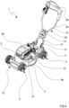
- the mobile device 1 of the present invention comprises a support frame 2 carrying the movement means 3, whether driven or idle, one or more work tools configured to perform the maintenance operations within the work area and an operating body 5 carrying and/or hosting the work tool 4 and defining an actuation region of the mobile device 1 configured to perform the maintenance operations.
- the movement means 3 can comprise wheels, in particular four wheels or tracks. The wheels can be arranged at the respective four vertices of the support frame 2, to define a rectangular or square polygonal shape.
- the mobile device 1 comprises a front portion 10, a rear portion 11 opposite to, and distanced from, the front portion 10, a left side 12 interposed as a connection between the front portion 10 and the rear portion 11 of the mobile device 1, and a right side 13 interposed as a connection between the front portion 10 and the rear portion 11 of the mobile device 1: the right side 13 is opposite and distanced from the left side 12.
- the left side 12 and the right side 13 comprise the movement means 3, the movement means 3 being wheels: the left side 12 and the right side 13 of the mobile device 1 comprise each two movement wheels placed at the front portion 10 and the other at the rear portion 11.
- the mobile device 1 has a front wheel axle 3a placed at the front portion 10 and comprising a left front wheel 3a' and a right front wheel 3a", and a rear wheel axle 3b placed at the rear portion 11 and comprising a left rear wheel 3b' and a right rear wheel 3b".
- An envelope of the four wheels i.e. an envelope defined by the left and right front wheels and the left and right rear wheels, defines a peripheral shape 7 of the mobile device 1.
- the mobile device 1 extends in length between the front portion 10 and the rear portion 11, to define a longitudinal axis X of the mobile device 1: in particular, the longitudinal axis X of the mobile device 1 crosses the front portion 10 and the rear portion 11 substantially orthogonally.
- the longitudinal axis X of the mobile device 1 can define an axis of symmetry between the left side 12 and the right side 13 of the mobile device 1 and pass through a central portion of the mobile device 1 itself.
- a straight advancement of the mobile device 1 can be coincident with the longitudinal axis X of the mobile device 1.
- the longitudinal axis X can be substantially orthogonal to the front and/or rear wheel axis of the mobile device 1 at least during a straight motion condition.
- the longitudinal axis X can be equidistant from the left and right wheels of the same axis: in such a case, the longitudinal axis defines a central longitudinal axis of the mobile device.
- the longitudinal axis X in the present description, is considered centrally placed to the mobile device.
- the movement means 3 define a support plane SP for the mobile device 1: in fact, such a support plane SP coincides with the ground during an operating condition of the mobile device 1.
- the support plane is passing through the points of contact between the wheels of the mobile device 1 and the ground on which the mobile device 1 is arranged.
- the rotary blade of the work tool 4 is movable about a rotation axis A which is transverse or substantially orthogonal to the support plane SP.
- the movement means 3 can further define a straight advancement of the mobile device 1 along a longitudinal advancement direction substantially coincident with the longitudinal axis X of the mobile device 1: in particular, the longitudinal advancement direction is substantially orthogonal to a rotation axis of the wheels of the mobile device 1.
- a longitudinal advancement direction is substantially parallel to the support plane SP: likewise the longitudinal axis X is parallel to the support plane SP.
- the mobile device 1 extends in width along a transverse axis W between a left side 12, interposed as a connection between the front portion 10 and the rear portion 11 of the mobile device 1, and a right side 13, also interposed as a connection between the front portion 10 and the rear portion 11 of the mobile device 1: the right side 13 is opposite and distanced with respect to said left side 12.
- the transverse axis W is orthogonal to the longitudinal axis X and to the vertical axis Z.
- the longitudinal axis X, the transverse axis W, and the vertical axis Z define a reference system of the mobile device 1, as shown in figure 1 .
- the origin of said reference system can be the mass or geometric centre of gravity of the mobile device.
- the rotation axis A of the rotary blade is substantially parallel or coincident with the vertical axis Z of the mobile device 1.
- the mobile device 1 in the case of a manually-driven mobile device 1 as shown in figures 1-5 , can comprise a drive handle 20 substantially constrained at the rear portion 11 of the mobile device 1 and configured to allow an operator to drive and optionally move, for example push, the mobile device 1 within the work area.
- the drive handle 20 can be made of metallic material, for example steel, iron or aluminium, or plastic or composite material.
- the drive handle 20 preferably extends along an inclined direction transverse to the operating body 5, in particular transverse to the support plane SP.
- the drive handle 20 defines in particular an angle with the support plane SP between 20° and 70°, more in particular between 30° and 50°.
- the handle extends at the rear of the mobile device 1 substantially from the rear portion 11 between a first end, connected at the rear portion 11 of the mobile device 1, and a second end configured to allow gripping by an operator: in particular the drive handle 20, being inclined with respect to the support plane, defines a horizontal projection on the support plane, in other words on the ground, and a vertical projection on the vertical axis of the mobile device 1.
- the horizontal projection extends from the rear portion 11 of the mobile device 1 along and towards a direction away from the rear portion 11 of the mobile device 1.
- the handle can be directly constrained to the operating body 5 of the mobile device 1 or to the support frame 2.
- the handle can be constrained at a first and a second hooking point to the mobile device 1, for example at a left hooking point and a right hooking point.
- the drive handle 20 defines a tool which the operator uses to push and/or guide the mobile device 1 within the work area.
- the operating body 5 can be made of metallic material, for example steel or aluminium, or plastic or composite material. It should be noted that the operating body is rigidly constrained to the work tool and to the relative motor: consequently, any movement of the operating plane forcibly determines a similar movement of the work tool and the relative motor. In other words, the operating body and the work tool are integral with each other: the only degree of freedom of the work tool with respect to the operating plane is the rotational one about the rotation axis A.
- the first and the second blade can have the same diameter, or alternatively, can have different diameters, for example in which the first rotary blade 4a has a smaller diameter with respect to the second rotary blade 4b.
- the operating body 5 can have an elongated shape to entirely cover the two rotary blades: in particular the operating body 5 can have an elongated and circular shape at the lateral ends thereof as in figure 11 .
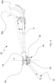
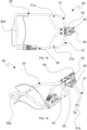
- the manually-driven mobile device 1 comprises the drive handle 20 emerging at the rear of the mobile device 1 and a coupling member, connected to the drive handle 20, configured to allow the movement of at least part of the drive handle 20 along a control axis D, as shown in figures 8A and 8B , and figures 14A and 14B in accordance with a further embodiment.
- the control axis D comprises at least one translational component substantially parallel with the transverse axis W: this means that the movement of the drive handle 20 can occur further along a vertical axis, or occur by rotation, while still comprising a movement component parallel with the transverse axis W.
- the coupling member is configured to allow the positioning, along the control axis D, of the drive handle 20 in:
- the right lateral position and the left lateral position of the drive handle 20 define the maximum movement end limits of the drive handle 20 along the control axis D.
- the drive handle 20 when arranged in the left lateral position and/or in the right lateral position, exceeds the lateral dimension limits defined by the movement means 3 of the mobile device 1.
- the maximum translation value of the drive handle along the control axis D useful for the movement of the operating body 5 is between 5 cm and 50 cm with respect to the central position.
- the coupling member comprises a rail configured to move the drive handle for translation along the control axis 40: in particular said translation being a movement of the handle along a straight trajectory and substantially orthogonal to the longitudinal axis X of the mobile device and optionally parallel to the translation axis Y of the operating body 5.
- the second member 22 of the handle extends laterally and in height from the joint 40 to define the gripping portion 22a of the drive handle 20.
- Such a fulcrum 41 comprises the first coupling element 42 firmly constrained to the first member 21 of the drive handle 20 and comprising a through hole, the second coupling element 43 firmly constrained to the second member 22 of the drive handle 20 and comprising a through hole, and a through pin 61 passing through the through hole of the first and second coupling element 43 and extending along the rotation axis B of the joint 40.
- Such an architecture defines a first member 21 of the drive handle 20 fixed and constrained to the mobile device 1, while the second member 22 of the drive handle 20 has at least one rotational degree of freedom about such a fulcrum 41 defining the rotation axis B, allowing the lateral movement of the second member 22 along the control axis D.
- the rotation axis B of the joint 40 is transverse to the support plane SP, and substantially parallel to, or lying on, a plane XZ passing through the longitudinal axis X and the vertical axis Z. Furthermore, the rotation axis B intersects a central axis of the mobile device 1 aligned with the longitudinal axis X. Furthermore, the rotation axis B is inclined, with respect to the longitudinal axis X along such a plane XZ, by an angle between 30° and 70°. Such an embodiment is shown in figure 21 .
- Figures 12-19 show a further embodiment in which the joint 40 is further configured to vary a height H of the gripping portion 22a of the drive handle 20 with respect to the support plane SP, as schematically shown in figure 15 : such a height is defined in particular by the distance interposed between the gripping portion 22a of the handle and the support plane SP.
- the first member 21 of the handle is fixed and constrained at the rear of the mobile device 1, while the second member 22 is movable in height.
- the joint 40 comprises a regulating insert 44 having a substantially sectional wedge shape, as highlighted in figures 16 and 17B .
- the regulating insert 44 is interposed between the first coupling element 42 and the second coupling element 43 of the joint 40 and is movable in rotation about the rotation axis B with respect to the first and/or second coupling element 43 of the joint 40.
- a rotation of the regulating insert 44 of the joint 40 with respect to the first and/or the second coupling element 43 determines a contextual variation in height of the gripping portion 22a of the drive handle 20 with respect to the support plane SP as in figure 15 .
- the regulating insert 44 radially extends substantially about the rotation axis B of the joint 40 and extends in thickness between a first abutment plane, configured to contact the first coupling element 42 of the drive handle 20 and a second abutment plane, configured to contact the second coupling element 43 of the drive handle 20: the first and the second abutment plane are inclined relative to each other at an angle ⁇ between 4° and 20°, in particular between 6° and 15°, more in particular between 8° and 12°, preferably equal to 10°.
- first and the second abutment plane of the regulating insert 44 are orthogonal to the vertical axis Z, in particular in which the first and the second abutment plane of the regulating insert 44 are both orthogonal to a plane XZ passing through the longitudinal axis X and the vertical axis Z.
- the first and second abutment plane of the regulating insert 44 thus determine a relative inclination between the first coupling element 42 and the second coupling element 43 and further determine the inclination of the rotation axis B of the joint 40 with respect to the support plane SP: such an inclination, as already specified, is projected on the plane XZ.
- the regulating insert 44 is rotatable about the rotation axis B: a rotation of the regulating insert 44 with respect to the first and/or the second coupling element 43 of the joint 40 determines a contextual variation of the inclination of the rotation axis B of the joint 40 with respect to the support plane, and in particular with respect to the first or the second abutment element: such a variation of inclination consequently determines the height variation of the gripping portion 22a of the drive handle 20, as shown in figure 15 .
- the second member 22 defines a rotary motion about a virtual axis C: such an axis C is defined as "virtual" because the joint 40 does not have a physical fulcrum aligned along the axis C, but such rotation is determined by the particular wedge shape of the regulating insert rotating about the rotation axis B which is orthogonal to the virtual axis C.
- the virtual axis C is schematically shown in figure 14B .
- the regulating insert 44 defines a disc-like regulating plate 44a having a wedge-like section along the plane XZ.
- the first coupling element 42 also defines a first disc-like plate 42a and has a first abutment plane adapted to contact the first abutment plane of the regulating plate 44a.
- the second coupling element 43 defines a second disc-like plate 43a, and has a second abutment plane adapted to contact the second abutment plane of the regulating plate 44a.
- the second member 22 of the actuator handle 20 is positionable at least in:
- the inclination of the second member 22 of the drive handle 20 can vary, between the lowered position and the raised position, by an angle between 4° and 20°, in particular between 6° and 15°, more in particular between 8° and 12°, preferably equal to 10°: the consequent variation in height of the handle thus depends on the extension in length of the second member 22 of the handle itself. It should be noted that such an inclination with respect to the support plane SP is measured on a plane XZ passing through the longitudinal axis X and the vertical axis Z of the mobile device 1.
- the closing system comprises a through pin 61 passing transversely in the respective central holes of the joint 40, i.e., through the first plate 42a of the joint 40, the regulating plate 44a, and the second plate 43a of the joint 40.
- the closing system further comprises a first stop element 62, for example a screwable knob for adjusting a useful length of said through pin 61, engaged at a first end of the through pin 61 and defining an abutment against at least one of the first and the second plate 43a of the joint 40, as shown in the sectional view of figure 17B .
- the closing system further comprises a second stop element 63, for example a manually operable closing lever, engaged at a second end of the through pin 61 and movable between a closing position and an opening position.
- the joint comprises the first coupling element 42 and the second coupling element 43 facing each other, each comprising respective teeth configured to cooperate with each other so as to inhibit a rotation of the first coupling element 42 with respect to the second coupling element 43: such teeth thus allow to inhibit the rotation of the second member 22 of the drive handle with respect to the first member 21 of the drive handle.
- the embodiment of figure 21 does not comprise the regulating insert 44: the first and the second coupling element 42, 43 of the joint 40 are thus in contact with each other to allow or inhibit mutual rotation.
- rotation axis A of the work tool 4 is substantially parallel to the vertical axis of the mobile device 1 and orthogonal to the translation axis Y of the operating body 5.
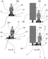
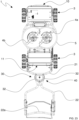
- the operating body 5 is movable along the translation axis Y between a right lateral position and a left lateral position, in which the left and right lateral position define the maximum end limits within which the operating body 5 is movable along the translation axis.
- a first end portion 5a of the operating body 5 has a maximum distance with respect to the central axis of the mobile device 1
- a second end portion 5b of the operating body 5, opposite the first end portion 5a has a minimum distance with respect to the central axis.
- the first and the second end portion 5b are placed along the translation axis Y: optionally the first end portion 5a is symmetrical with respect to the second end portion 5b with respect to the central axis of the mobile device 1.
- the first end portion 5a of the operating body 5 has a minimum distance with respect to said central axis, while the second end portion 5b of the operating body 5 has a maximum distance with respect to the central axis.
- a line passing through the first and the second end portion 5b of the operating body 5 can be aligned or parallel with the translation axis Y.
- the device comprises one or more rails 6 firmly constrained to the support frame 2 and carrying the operating body 5: such rails 6 can be bolted or welded to the support frame 2 and are fixed with respect to the frame.
- the rails 6 extend in length parallel to the transverse axis W of the mobile device 1.
- the rails 6 have an elongated cylindrical shape.
- the mobile device 1 preferably comprises a first and a second rail 6a, 6b parallel to each other and extending in length along a respective direction in length parallel to the translation axis Y: the first and the second rail 6a, 6b extend in length between a respective first end facing the right side 13 of the mobile device 1, and a second end facing the left side 12 of the mobile device 1.
- the guides support the operating body 5 vertically and prevent the movement thereof along the longitudinal axis X, simultaneously allowing the operating body to move along the translation axis Y.
- the mobile device 1 comprises a first and a second guide 8a, 8b each comprising a respective eyelet having a through opening: the first rail 6a is inserted in the through opening of the eyelet of the first guide, while the second rail 6b is inserted in the through opening of the eyelet of the second guide.
- the first and the second guide 8a, 8b are thus slidable on the respective first and second rail 6a, 6b, allowing the mobility of the operating body 5 along the translation axis Y.
- each eyelet defines a central axis parallel to the translation axis Y: in particular, this central axis of each eyelet is substantially coincident with the extension in length of the rail which passes through it.
- the eyelet can be made of metal or plastic.
- a bushing of low friction material for example plastic or polytetrafluoroethylene PTFE, can be interposed between the eyelet and the rail so as to facilitate the relative sliding.
- a recirculating ball bearing can be interposed between the eyelet and the rail so as to further improve the relative sliding.
- the actuation system 30, connected to the joint 40, is then configured to determine, in response to a displacement of the drive handle 20 along the control axis D, the movement of the operating body 5 along the translation axis Y.
- a movement of the drive handle 20 along the control axis in a first direction determines a simultaneous movement of the operating body 5 along the translation axis Y in a second direction opposite the first direction and vice versa.
- a movement of the drive handle 20 to the left determines a contextual movement of the operating body 5 to the right: similarly, a movement of the drive handle 20 to the right, determines a contextual movement of the operating body 5 to the left.
- the drive handle 20 lies on a transverse actuation plane with respect to a plane of the operating body 5 and is transverse with respect to the support plane. In the event of a rotation of the drive handle 20, the latter rotates along said actuation plane, such that the rotation axis B of the handle is orthogonal to the actuation plane on which the drive handle 20 lies.
- the rotation axis B of the actuation system 30 can be located at a median portion of the drive handle 20 placed between the first and the second end of the handle. In other words, the median portion is interposed between, and optionally substantially equidistant from, the first and the second end of the actuator handle 20. Since the drive handle 20 is inclined, the actuation system 30 is located at a greater distance with respect to the support plane with respect to a similar distance between the first end and the support plane. In particular, the actuation system 30 is positioned at a distance from the support plane between 20 cm and 100 cm, in particular between 25 cm and 60 cm.
- the actuation system 30 preferably comprises one or more drive cables 31 connecting the actuation system 30, in particular the drive handle 20 or the control lever 90, to the operating body 5: the connection cables are configured to transmit a movement of the drive handle 20 along the control axis D, or a movement of the control lever 90, to the operating body 5 to determine the simultaneous movement along the translation axis Y.
- a movement of the drive handle 20 along the control axis D results in a proportional movement in amplitude of the operating body 5 along the translation axis Y, in particular in which an increase of a movement of the drive handle 20 along the control axis D results in a proportional increase of a movement of the operating body 5 along the translation axis Y.
- the more an operator moves the drive handle 20 towards the left or towards the right the more the operating body 5 will move accordingly.
- the second drive cable 31b extends in length between a first end, constrained to a second portion of the operating body, and a second end connected to the joint, in particular to a traction element 32 of the joint 40.
- the first and the second portion of the operating body 5 to which the respective cables 31a, 31b are constrained are opposite each other with respect to the rotation axis A of the work tool: in particular the first portion is placed on the right side of the mobile device, while the second portion is arranged on the left side of the mobile device.
- the actuation system 30 can comprise a single drive cable, as shown in figure 3 , extending between a first end and a second end both connected to the operating body 5, and in which the single drive cable transits through the joint 40: the single cable can be wound to the joint 40 or is constrained to a traction element 32 of the joint.
- the first end of the single drive cable is connected to a right portion of the operating body, while the second end of the single drive cable is connected to a left portion of the operating body.
- the actuation system 30 can comprise a single drive cable, as shown in figure 4 and 5 , extending between a first end, connected to a portion of the operating body, and a second end connected to the control lever 90.
- the single drive cable can pass through the joint 40 to reach the control lever located near or at the gripping portion 22a of the drive handle.
- the actuation system 30 can comprise a return element, for example a traction or compression spring, interposed in connection between the operating body 5 and the support frame 2 and configured to move the operating body 5 along a return direction opposite a drive direction determined by the single drive cable.
- the return element is configured to pull the operating body towards the left, such that when the operator releases the control lever 90, the operating body is moved by the return element towards the left, for example in the central position.
- the return element is configured to pull the operating body towards the right, such that when the operator releases the control lever 90, the operating body is moved by the return element towards the right, for example in the central position.
- the actuation system 30 can comprise one or more drive cables 31, for example one or two drive cables, in which at least one end of the drive cable is constrained to a pulling portion 2a of the support frame 2, and in which the drive cable passes through the operating body 5.
- Such an actuation system can further comprise at least one sheath 35 for each drive cable 31: the sheath 35 can be flexible or rigid.
- the drive cable 31 is inserted into the respective sheath 35 and extends between a first end 31', constrained to the pulling portion 2a of the support frame a, and a second end 31" connected to the control lever 90 or to the joint of the drive handle 20: similarly the sheath 35 extends between a respective first end 35' and second end 35".
- the operating body 5 comprises a respective pulling portion 15 comprising a through hole for the passage of the drive cable 31, in which the pulling portion 15 of the operating body 5 is interposed between the first end 31' of the drive cable 31 and the first end 35' of the sheath 35: in particular the first end 35' of the sheath 35 is abutting the pulling portion 15 of the operating body 5.
- a traction of the winding cable 31 determines the simultaneous movement of the operating body towards the left or right side of the mobile device, in particular so that the first end 31' of the drive cable 31 approaches the pulling portion 15 of the operating body 5.
- Figures 6 and 7 show an embodiment of the actuation system 30 of the drive handle 20 which allows the operating body 5 to be moved along the translation axis Y in response to a lateral movement of the drive handle 20 along the control axis D.
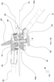
- the actuation system 30 comprises a traction element 32 constrained to the drive handle 20 at the joint 40 and movable by rotation substantially about the rotation axis B of said joint 40, such that a rotation of the drive handle 20 determines a similar rotation of the traction element 32.
- the traction element 32 is thus configured to pull, during a rotation of the drive handle 20, the cables 31 to move the operating body 5 along the translation axis Y towards the left side 12 and the right side 13 of the mobile device 1.
- the traction element 32 has a circular or semicircular shaped side surface radially spaced from the rotation axis B of the joint 40: the drive cables 31 are at least partially wound around the side surface of the traction element 32, as shown in figures 2 and 3 .
- the first cable can be wound to a right portion of the side surface
- the second cable can be wound to a left portion of the side surface: it should be noted that the left portion of the side surface faces the left side 12 of the mobile device 1, while the right portion of the side surface faces the right side 13 of the mobile device 1.
- the mobile device 1 does not comprise the drive handle 20.
- the self-driving mobile device 1 can comprise at least one obstacle detector 9 configured to detect one or more obstacles in the work area during a movement of the mobile device 1 in the work area.
- the obstacle detector 9 can comprise at least one of a proximity sensor, for example an ultrasonic or optical sensor, a camera, or a flight time sensor. If a camera is present, a control unit 50 can be configured to detect and optionally recognize an obstacle 100, for example, identifying the obstacle 100.
- the control system related to self-driving can comprise a peripheral wire system, a GPS sensor guidance system, or one or more cameras. The self-driving control system will not be described in detail, as it is already part of the prior art.
Landscapes
- Life Sciences & Earth Sciences (AREA)
- Environmental Sciences (AREA)
- Harvester Elements (AREA)
- Agricultural Machines (AREA)
- Control Of Position, Course, Altitude, Or Attitude Of Moving Bodies (AREA)
- Vehicle Cleaning, Maintenance, Repair, Refitting, And Outriggers (AREA)
Claims (15)
- Dispositif mobile (1) à entraînement manuel pour l'entretien des terres, comprenant un cadre de support (2) portant :- des moyens de déplacement (3) configurés pour permettre ou déterminer un déplacement du dispositif mobile (1), lesdits moyens de déplacement (3) définissant un plan de support (SP) pour le dispositif mobile (1) ;- au moins un outil de travail (4) configuré pour effectuer des opérations de maintenance ;- un corps opérationnel (5) portant et/ou logeant ledit outil de travail (4),dans lequel ledit dispositif mobile (1) s'étend :- en longueur entre une partie avant (10) et une partie arrière (11) pour définir un axe longitudinal (X) du dispositif mobile (1), et- en hauteur le long d'un axe vertical (Z) orthogonal audit axe longitudinal (X) et audit plan de support (SP),- en largeur le long d'un axe transversal (W) entre un côté gauche (12), interposé en tant que liaison entre la partie avant (10) et la partie arrière (11) du dispositif mobile (1), et un côté droit (13), également interposé en tant que liaison entre la partie avant (10) et la partie arrière (11) du dispositif mobile (1), ledit côté droit (13) étant opposé audit côté gauche (12) et positionné à une certaine distance de celui-ci, ledit axe transversal (W) étant orthogonal audit axe longitudinal (X),dans lequel ledit dispositif mobile (1) comprend :- une poignée d'entraînement (20) configurée pour permettre à un opérateur d'entraîner ledit dispositif mobile (1),- un système d'articulation efficace entre ledit corps opérationnel (5) et ledit cadre de support (2) et configuré pour permettre audit corps opérationnel (5) d'être déplacé transversalement audit cadre de support (2) et- un système d'actionnement relié de manière opérationnelle audit système d'articulation de manière à déterminer des variations dans la position transversale dudit corps opérationnel (5) par rapport audit cadre de support (2),dans lequel ledit système d'actionnement est relié à ladite poignée d'entraînement (20), dans lequel ledit dispositif mobile (1) comprend un ou plusieurs rails (6) contraignant le corps opérationnel (5) au cadre de support (2) et configurés pour permettre le déplacement du corps opérationnel (5) le long d'au moins un axe de translation (Y), ledit axe de translation (Y) étant parallèle audit axe transversal (W) ou coïncidant avec celui-ci ou ledit axe de translation (Y) définissant avec ledit axe transversal (W) un angle inférieur à 45°,dans lequel une enveloppe des moyens de déplacement (3) définit un contour périphérique (7) du dispositif mobile (1), etdans lequel les moyens de déplacement (3) comprennent :- au moins deux roues placées au niveau d'une partie avant (10) du dispositif mobile (1), et- au moins deux roues au niveau d'une partie arrière (11) du dispositif mobile (1), lesdites roues définissant le contour périphérique (7) du dispositif mobile (1),le dispositif mobile (1) étant caractérisé en ce qu'un déplacement du corps opérationnel (5) le long de l'axe de translation (Y) permet au corps opérationnel (5) d'émerger d'une quantité variable par rapport audit contour périphérique (7).
- Dispositif mobile (1) selon la revendication précédente, dans lequel le corps opérationnel (5) est mobile le long dudit axe de translation (Y) vers ledit côté gauche (12) et vers ledit côté droit (13) du dispositif mobile (1), et/oudans lequel ledit axe de translation (Y) est parallèle audit plan de support (SP), dans lequel, pendant un état opérationnel du dispositif mobile (1), le corps opérationnel (5) est mobile parallèlement au sol,ledit axe de translation (Y) étant :- orthogonal audit axe longitudinal (X) du dispositif mobile (1), et- orthogonal audit axe vertical (Z),dans lequel le corps opérationnel (5) est mobile :- en hauteur le long dudit axe vertical (Z) entre une position distale et une position proche du sol, par rapport au plan de support (SP), et- le long dudit axe de translation (Y),ledit axe vertical (Z) et ledit axe de translation (Y) étant orthogonaux l'un à l'autre.
- Dispositif mobile (1) selon l'une quelconque des revendications précédentes, dans lequel un état de mouvement rectiligne du dispositif mobile (1) définit une direction d'avancement longitudinale, ladite direction d'avancement longitudinale coïncidant avec ledit axe longitudinal (X) du dispositif mobile (1), et/oudans lequel les moyens de déplacement (3) comprennent un axe de déplacement avant (3a) comprenant une roue avant gauche (3a') et une roue avant droite (3a"), et un axe de déplacement arrière (3b) comprenant une roue arrière gauche (3b') et une roue arrière droite (3b"),ledit axe longitudinal (X) étant orthogonal audit axe de déplacement avant (3a) et/ou audit axe de déplacement arrière (3b) du dispositif mobile (1),ledit axe de translation (Y) étant parallèle audit axe de déplacement avant (3a) et/ou audit axe de déplacement arrière (3b),dans lequel, un premier point étant donné par l'intersection entre ledit axe longitudinal (X) et la projection dudit axe de translation (Y) sur un plan parallèle audit plan de support (SP) et passant à travers ledit axe longitudinal (X), un deuxième point étant donné par l'intersection entre ledit axe longitudinal (X) et la projection dudit axe de déplacement avant (3a) sur un plan parallèle audit plan de support (SP) et passant à travers ledit axe longitudinal (X) et un troisième point étant donné par l'intersection entre ledit axe longitudinal (X) et la projection dudit axe de déplacement arrière (3b) sur un plan parallèle audit plan de support (SP) et passant à travers ledit axe longitudinal (X), il est possible que ledit premier point soit interposé entre ledit deuxième point et ledit troisième point,dans lequel ledit axe longitudinal (X) est équidistant d'une roue gauche et d'une roue droite du même axe de déplacement du dispositif mobile (1), ledit axe longitudinal (X) étant un axe de symétrie longitudinale du dispositif mobile (1), et/oudans lequel le corps opérationnel (5) est mobile le long de l'axe de translation (Y) entre une position latérale droite et une position latérale gauche, lesdites positions latérales gauche et droite définissant les limites d'extrémité maximales à l'intérieur desquelles ledit corps opérationnel (5) est mobile le long de l'axe de translation (Y), dans lequel une translation maximale entre ledit axe longitudinal (X) et ladite position latérale droite et/ou gauche est comprise entre 10 cm et 80 cm, et/oudans lequel :- lorsque le corps opérationnel (5) est dans la position latérale droite,o une première partie d'extrémité (5a) du corps opérationnel (5) a une distance maximale par rapport audit axe longitudinal (X), eto une seconde partie d'extrémité (5b) du corps opérationnel (5), opposée à ladite première partie d'extrémité (5a), a une distance minimale par rapport à l'axe longitudinal (X),- lorsque le corps opérationnel (5) est dans la position latérale gauche,o la première partie d'extrémité (5a) du corps opérationnel (5) a une distance minimale par rapport audit axe longitudinal (X), eto la seconde partie d'extrémité (5b) du corps opérationnel (5), opposée à ladite première partie d'extrémité (5a), a une distance maximale par rapport à l'axe longitudinal (X),dans lequel une ligne passant à travers lesdites première et seconde parties d'extrémité (5b) du corps opérationnel (5) coïncide avec l'axe de translation (Y) ou est parallèle à celui-ci, et/oudans lequel le corps opérationnel (5) peut être positionné dans une position centrale interposée entre ladite position latérale gauche et ladite position latérale droite, ladite position centrale agissant comme une position de référence pour ledit corps opérationnel (5),dans ladite position centrale, la première et la seconde partie d'extrémité (5b) du corps opérationnel (5) étant équidistantes par rapport à l'axe longitudinal (X) du dispositif mobile (1),dans lequel, dans ladite position centrale, le corps opérationnel (5) n'émerge pas ou émerge moins du contour périphérique (7) du dispositif mobile (1) par rapport à la position latérale gauche ou droite.
- Dispositif mobile (1) selon l'une quelconque des revendications précédentes, dans lequel :- lorsque le corps opérationnel (5) est dans la position latérale droite, le corps opérationnel (5) émerge partiellement vers la droite par rapport audit contour périphérique (7) et n'émerge pas vers la gauche par rapport audit contour périphérique (7),- lorsque le corps opérationnel (5) est dans la position latérale gauche, le corps opérationnel (5) émerge partiellement vers la gauche par rapport audit contour périphérique (7) et n'émerge pas vers la droite par rapport audit contour périphérique (7).
- Dispositif mobile (1) selon l'une quelconque des revendications précédentes, dans lequel le dispositif mobile (1) est une tondeuse à gazon et l'outil de travail (4) est une lame rotative mobile par rotation autour d'un axe de rotation (A),dans lequel ledit axe de translation (Y) est orthogonal audit axe de rotation (A),dans lequel ledit axe de rotation (A) de la lame rotative est mobile pour translation le long dudit axe de translation (Y) en même temps que le corps opérationnel (5), etdans lequel ledit axe de rotation (A) de la lame rotative est orthogonal au plan de support lorsqu'il est disposé dans la position latérale droite, dans la position latérale gauche et dans la position centrale du corps opérationnel (5).
- Dispositif mobile (1) selon l'une quelconque des revendications précédentes, dans lequel lesdits un ou plusieurs rails (6) comprennent un premier rail et un second rail (6a, 6b) parallèles l'un à l'autre et s'étendant en longueur le long d'une direction respective parallèle à l'axe de translation (Y),dans lequel le premier rail (6a) est agencé au niveau de la partie avant (10) du dispositif mobile (1), tandis que le second rail (6b) est agencé au niveau de la partie arrière (11) du dispositif mobile (1),dans lequel ladite direction de longueur du premier rail (6a) et du second rail (6b) est orthogonale à l'axe longitudinal (X) et parallèle au plan de support (SP), ladite direction longueur du premier rail (6a) et du second rail (6b) étant parallèle à l'axe transversal (W) défini par l'extension en largeur du dispositif mobile (1),et dans lequel le corps opérationnel (5) comprend un premier et un second guide (8a, 8b) coopérant chacun avec le premier et le second rail (6a, 6b), respectivement, pour permettre le déplacement relatif entre le rail et le corps opérationnel (5),lesdits premier et second guides (8a, 8b) comprenant chacun au moins un œillet respectif ayant une ouverture traversante, le premier rail (6a) étant inséré dans l'ouverture traversante de l'œillet du premier guide (8a), tandis que le second rail (6b) est inséré dans l'ouverture traversante de l'œillet du second guide (8b),les premier et second guides (8a, 8b) pouvant coulisser sur les premier et second rails (6a, 6b) respectifs pour permettre la mobilité du corps opérationnel (5) le long de l'axe de translation (Y),dans lequel le premier guide (6a) est situé au niveau de la partie avant (10) du dispositif mobile (1), tandis que le second guide (6b) est situé au niveau de la partie arrière (11) du dispositif mobile (1).
- Dispositif mobile (1) selon l'une quelconque des revendications précédentes, dans lequel ledit système d'actionnement comprend un joint (40) configuré pour permettre, au moins dans un état d'actionnement, un déplacement de ladite poignée d'entraînement (20) ou d'au moins une partie de ladite poignée d'entraînement (20) vers un côté gauche (12) et/ou vers un côté droit (13) du dispositif mobile (1) le long d'au moins un axe de commande (D), ledit axe de commande comprenant au moins un composant parallèle à l'axe de translation (Y) du corps opérationnel (5), et dans lequel ledit joint (40) du système d'actionnement est configuré pour déterminer, lors d'un déplacement de ladite poignée d'entraînement (20) ou de ladite au moins une partie de ladite poignée d'entraînement (20) le long de l'axe de commande (D) et/ou lors d'un basculement ou d'une variation de la position de ladite poignée d'entraînement (20) ou de ladite au moins une partie de ladite poignée d'entraînement (20) dans la direction dudit axe de commande (D), le déplacement simultané du corps opérationnel (5) le long de l'axe de translation (Y).
- Dispositif mobile (1) selon l'une quelconque des revendications 1 à 6, dans lequel ledit système d'actionnement comprend un levier de commande (90) porté par la poignée et pouvant être entraîné par un opérateur par translation ou rotation et relié de manière opérationnelle au corps opérationnel (5), ledit levier de commande (90) étant configuré pour déterminer, lorsqu'il est déplacé, un déplacement simultané du corps opérationnel (5) le long de l'axe de translation (Y).
- Dispositif mobile (1) selon la revendication 7, dans lequel le système d'actionnement comprend un ou plusieurs câbles d'entraînement (31) reliant le système d'actionnement au corps opérationnel (5),lesdits câbles d'entraînement (31) étant configurés pour transmettre un déplacement de la poignée d'entraînement (20) le long de l'axe de commande (D), ou un déplacement du levier de commande (90), au corps opérationnel (5) pour déterminer le déplacement simultané le long de l'axe de translation (Y),et dans lequel un déplacement de la poignée d'entraînement (20) le long de l'axe de commande (D) détermine un déplacement proportionnel en amplitude du corps opérationnel (5) le long de l'axe de translation (Y).
- Dispositif mobile (1) selon la revendication 9, dans lequel le système d'actionnement comprend :- un câble d'entraînement unique s'étendant entre une première extrémité et une seconde extrémité toutes deux reliées au corps opérationnel (5), ledit câble d'entraînement unique passant à travers ledit joint (40), dans lequel la première extrémité dudit câble d'entraînement unique est reliée à une partie droite du corps opérationnel (5), tandis que la seconde extrémité dudit câble d'entraînement unique est reliée à une partie gauche du corps opérationnel (5) ; ou- un câble d'entraînement unique s'étendant entre une première extrémité, reliée à une partie du corps opérationnel, et une seconde extrémité reliée au levier de commande (90) ou au joint (40), ledit câble d'entraînement unique passant à travers ledit joint (40), dans lequel le système d'actionnement comprend un élément de retour interposé en liaison entre le corps opérationnel et le cadre de support, ledit élément de retour étant configuré pour déplacer ledit corps opérationnel le long d'une direction de retour opposée à une direction d'entraînement déterminée par ledit câble d'entraînement unique ; ou- un premier câble d'entraînement et un second câble d'entraînement (31a, 31b) placés chacun en liaison entre la poignée d'entraînement (20) et le corps opérationnel (5) ou entre le levier de commande (90) et le corps opérationnel (5), dans lequel le premier câble d'entraînement (31a) est configuré pour tirer le corps opérationnel (5) vers la droite le long de l'axe de translation (Y), et le second câble d'entraînement (31b) est configuré pour tirer le corps opérationnel (5) vers la gauche le long de l'axe de translation (Y).
- Dispositif mobile (1) selon la revendication 7 ou la revendication 9 ou la revendication 10, dans lequel le système d'actionnement comprend un élément de traction (32) contraint à la poignée d'entraînement (20) au niveau du joint (40), ledit élément de traction (32) étant mobile par rotation autour d'un axe de rotation (B) dudit joint (40), de sorte qu'une rotation de ladite poignée d'entraînement (20) détermine une rotation similaire dudit élément de traction (32),ledit élément de traction (32) étant configuré pour tendre, pendant une rotation de ladite poignée d'entraînement (20), lesdits un ou plusieurs câbles pour déplacer le corps opérationnel (5) le long de l'axe de translation (Y) vers le côté gauche (12) et le côté droit du dispositif mobile (1),ledit élément de traction (32) ayant au moins une surface latérale de forme circulaire ou semi-circulaire espacée radialement de l'axe de rotation (B) du joint (40),et dans lequel lesdits un ou plusieurs câbles d'entraînement (31) sont au moins partiellement enroulés autour de ladite surface latérale et contraints à l'élément de traction (32),ledit premier câble étant enroulé sur une partie droite de ladite surface latérale, ledit second câble étant enroulé sur une partie gauche de ladite surface latérale à la place, dans lequel ladite partie gauche de la surface latérale fait face au côté gauche (12) du dispositif mobile (1), tandis que ladite partie droite de la surface latérale fait face au côté droit (13) du dispositif mobile (1).
- Dispositif mobile (1) selon la revendication 7 ou la revendication 9 ou la revendication 10 ou la revendication 11, dans lequel le système d'actionnement est configuré pour permettre une rotation de la poignée d'entraînement (20) autour d'un axe de rotation (B) du joint (40), ladite rotation de la poignée d'entraînement (20) définissant le déplacement de la poignée d'entraînement (20) elle-même le long de l'axe de commande (D),dans lequel une rotation de la poignée d'entraînement (20) autour de l'axe de rotation (B) du joint (40) entraîne une translation du corps opérationnel (5) le long de l'axe de translation (Y) proportionnelle en amplitude à ladite rotation, dans lequel une augmentation d'une rotation de la poignée d'entraînement (20) le long de l'axe de commande (D) entraîne une augmentation proportionnelle de la translation du corps opérationnel (5) le long de l'axe de translation (Y),ledit déplacement de la poignée d'entraînement (20) le long de l'axe de commande étant une projection horizontale du mouvement de rotation de la poignée d'entraînement (20), et dans lequel :- un déplacement le long de l'axe de commande (D) de la poignée d'entraînement (20) dans une position latérale droite respective détermine un déplacement simultané du corps opérationnel (5) dans la position latérale gauche,- un déplacement le long de l'axe de commande (D) de la poignée d'entraînement (20) dans une position latérale gauche respective détermine un déplacement simultané du corps opérationnel (5) dans la position latérale droite respective,- le positionnement le long de l'axe de commande (D) de la poignée d'entraînement (20) dans une position centrale respective détermine un déplacement simultané du corps opérationnel (5) dans une position centrale respective,ladite position latérale droite et ladite position latérale gauche de la poignée d'entraînement (20) définissant les limites d'extrémité maximales de la poignée d'entraînement (20) le long de l'axe de commande (D), ladite position centrale de la poignée étant interposée entre ladite position latérale droite et ladite position latérale gauche,dans lequel la poignée d'entraînement (20), lorsqu'elle est agencée dans la position latérale gauche et/ou dans la position latérale droite, dépasse les limites du contour périphérique (7) défini par les moyens de déplacement (3) du dispositif mobile (1).
- Dispositif mobile (1) selon l'une quelconque de la revendication 7 ou de la revendication 9 ou de la revendication 10 ou de la revendication 11 ou de la revendication 12, dans lequel le système d'actionnement comprend un système de mise en prise (33) actif sur le joint (40) et configurable dans :- une position de verrouillage dans laquelle le système de mise en prise (33) est configuré pour verrouiller le joint (40) afin d'empêcher le déplacement de la poignée d'entraînement (20) au moins le long de l'axe de commande (D) et- une position de déverrouillage dans laquelle le système de mise en prise (33) est configuré pour libérer le joint (40) et permettre le déplacement de la poignée d'entraînement (20) au moins le long de l'axe de commande (D),ledit système de mise en prise (33) comprenant un élément d'activation (34) configuré pour être entraîné par un opérateur et pour agencer sélectivement le système de mise en prise (33) dans la position de verrouillage ou dans la position de déverrouillage,l'élément d'activation (34) étant relié audit joint (40) au moyen d'un câble de liaison.
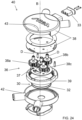
- Dispositif mobile (1) selon la revendication 7 ou la revendication 9 ou la revendication 10 ou la revendication 11 ou la revendication 12 ou la revendication 13, dans lequel ladite poignée d'entraînement (20) comprend :- un premier organe (21) s'étendant sur une première longueur entre :o une première extrémité, contrainte à une partie arrière (11) du dispositif mobile (1), eto une seconde extrémité portant ou comprenant au moins une première plaque (42a) ;- un second organe (22), mobile et distinct par rapport audit premier organe (21) de la poignée d'entraînement (20), s'étendant sur une seconde longueur entre :o une première extrémité comprenant ou portant au moins une seconde plaque (43a), ladite seconde plaque (43a) étant contrainte à la première plaque (42a) du premier organe (21) de la poignée d'entraînement (20), eto une seconde extrémité comprenant une partie de préhension (22a) configurée pour être saisie par un opérateur,ladite première plaque (42a) et ladite seconde plaque (43a) définissant le joint (40) et comprenant des surfaces de butée respectives se faisant face, dans lequel ladite première plaque (42a) et ladite seconde plaque (43a) sont mobiles l'une par rapport à l'autre par rotation, au moins dans un état de déverrouillage, autour de l'axe de rotation (B) du joint (40),et dans lequel le système d'actionnement comprend un train épicycloïdal (36) interposé de manière opérationnelle entre le premier organe (21) et le second organe (22) de la poignée d'entraînement (20) et configuré pour augmenter ou réduire un déplacement latéral du corps opérationnel (5) le long de l'axe de translation (Y) en réponse à une même rotation du second organe (22) de la poignée d'entraînement (20) autour de l'axe de rotation (B),dans lequel ledit train épicycloïdal (36) comprend :- au moins un pignon central (37) ayant un axe de rotation parallèle à l'axe de rotation (B) du joint (40) ou coïncidant avec celui-ci ;- une couronne circulaire externe (39) ayant des dents internes, mobile par rotation autour de l'axe de rotation du pignon central (37) ;- au moins un train d'engrenages (38) portant un ou plusieurs satellites (38a, 38b, 38c) et mobile par rotation autour de l'axe de rotation du pignon central (37), lesdits un ou plusieurs satellites (38a, 38b, 38c) étant interposés radialement entre le pignon central (37) et la couronne circulaire externe (39) et s'engrenant avec le pignon central (37) et la couronne circulaire externe (39).
- Dispositif mobile (1) selon la revendication 14, dans lequel :- la couronne circulaire externe (39) est contrainte au premier organe (21) de la poignée d'entraînement (20) et solidaire de celui-ci, ladite couronne circulaire externe (39) étant fixe par rapport au second organe (22) et fermement contrainte à la première plaque (42a) ;- le train d'engrenages (38) est contraint au second organe (22) de la poignée d'entraînement (20) et solidaire de celui-ci, dans lequel le train d'engrenages est contraint à la seconde plaque (43a), de sorte qu'une rotation du second organe (22) autour de l'axe de rotation (B) du joint (40) détermine une rotation simultanée du train d'engrenages (38) autour de l'axe de rotation du train d'engrenages (38), chaque satellite (38a, 38b, 38c) étant mobile par rotation autour d'un axe de rotation (D) de celui-ci et autour de l'axe de rotation du train d'engrenages (38),- le pignon central (37) est solidaire de l'élément de traction (32), ledit élément de traction (32) étant une poulie reliée de manière opérationnelle au (x) câble(s) d'entraînement (31) pour transmettre le mouvement au corps opérationnel (5).
Priority Applications (1)
| Application Number | Priority Date | Filing Date | Title |
|---|---|---|---|
| EP25185602.7A EP4599660A3 (fr) | 2021-08-31 | 2022-08-29 | Dispositif mobile avec système d'articulation fonctionnellement connecté et système d'actionnement |
Applications Claiming Priority (1)
| Application Number | Priority Date | Filing Date | Title |
|---|---|---|---|
| IT102021000022616A IT202100022616A1 (it) | 2021-08-31 | 2021-08-31 | Dispositivo mobile equipaggiato di mezzi di regolazione della posizione di un carico utile, segnatamente di un organo di taglio di erba |
Related Child Applications (1)
| Application Number | Title | Priority Date | Filing Date |
|---|---|---|---|
| EP25185602.7A Division EP4599660A3 (fr) | 2021-08-31 | 2022-08-29 | Dispositif mobile avec système d'articulation fonctionnellement connecté et système d'actionnement |
Publications (3)
| Publication Number | Publication Date |
|---|---|
| EP4140280A1 EP4140280A1 (fr) | 2023-03-01 |
| EP4140280C0 EP4140280C0 (fr) | 2025-07-09 |
| EP4140280B1 true EP4140280B1 (fr) | 2025-07-09 |
Family
ID=78649828
Family Applications (6)
| Application Number | Title | Priority Date | Filing Date |
|---|---|---|---|
| EP22192622.3A Active EP4140280B1 (fr) | 2021-08-31 | 2022-08-29 | Dispositif mobile avec un système d'articulation agencé entre un corps d'operation et un châssis de support et avec un système d'actionnement relié fonctionnellement au système d'articulation |
| EP25176209.2A Pending EP4595738A3 (fr) | 2021-08-31 | 2022-08-29 | Dispositif mobile autonome comprenant un corps de commande logeant un outil de travail et mobile le long d'un axe de translation |
| EP22192626.4A Pending EP4165975A1 (fr) | 2021-08-31 | 2022-08-29 | Dispositif mobile avec un système d'articulation agencé entre un corps d'operation et un châssis de support et avec un système d'actionnement relié fonctionnellement au système d'articulation |
| EP22192631.4A Active EP4140281B1 (fr) | 2021-08-31 | 2022-08-29 | Dispositif mobile avec un système d'articulation agencé entre un corps d'operation et un châssis de support et avec un système d'actionnement relié fonctionnellement au système d'articulation |
| EP23220723.3A Active EP4368009B1 (fr) | 2021-08-31 | 2022-08-29 | Dispositif mobile avec système d'articulation efficace entre un corps de manoeuvre et un cadre support et avec une conduite flexible interposée entre le corps de manoeuvre et le cadre support |
| EP25185602.7A Pending EP4599660A3 (fr) | 2021-08-31 | 2022-08-29 | Dispositif mobile avec système d'articulation fonctionnellement connecté et système d'actionnement |
Family Applications After (5)
| Application Number | Title | Priority Date | Filing Date |
|---|---|---|---|
| EP25176209.2A Pending EP4595738A3 (fr) | 2021-08-31 | 2022-08-29 | Dispositif mobile autonome comprenant un corps de commande logeant un outil de travail et mobile le long d'un axe de translation |
| EP22192626.4A Pending EP4165975A1 (fr) | 2021-08-31 | 2022-08-29 | Dispositif mobile avec un système d'articulation agencé entre un corps d'operation et un châssis de support et avec un système d'actionnement relié fonctionnellement au système d'articulation |
| EP22192631.4A Active EP4140281B1 (fr) | 2021-08-31 | 2022-08-29 | Dispositif mobile avec un système d'articulation agencé entre un corps d'operation et un châssis de support et avec un système d'actionnement relié fonctionnellement au système d'articulation |
| EP23220723.3A Active EP4368009B1 (fr) | 2021-08-31 | 2022-08-29 | Dispositif mobile avec système d'articulation efficace entre un corps de manoeuvre et un cadre support et avec une conduite flexible interposée entre le corps de manoeuvre et le cadre support |
| EP25185602.7A Pending EP4599660A3 (fr) | 2021-08-31 | 2022-08-29 | Dispositif mobile avec système d'articulation fonctionnellement connecté et système d'actionnement |
Country Status (5)
| Country | Link |
|---|---|
| EP (6) | EP4140280B1 (fr) |
| DE (1) | DE202022003238U1 (fr) |
| ES (1) | ES3033418T3 (fr) |
| IT (1) | IT202100022616A1 (fr) |
| PL (2) | PL4140281T3 (fr) |
Family Cites Families (17)
| Publication number | Priority date | Publication date | Assignee | Title |
|---|---|---|---|---|
| AU462048B2 (en) | 1973-04-13 | 1975-06-12 | Rover Mowers Pty. Ltd | Improvements in and relating to mowers |
| DE8709285U1 (de) * | 1987-07-06 | 1987-10-01 | Leonhard Weiss GmbH & Co Niederlassung Crailsheim, 7180 Crailsheim | Gerät zum Niedrighalten des Bewuchses von Gleistrassen |
| US5771672A (en) * | 1994-04-22 | 1998-06-30 | Gummerson; Elwyn | Laterally and vertically movable grass cutting mower attachment |
| DE4428373C1 (de) | 1994-08-11 | 1996-02-22 | Wolf Outils | Lenkergestänge für Rasenmäher |
| US6065276A (en) * | 1997-01-24 | 2000-05-23 | Deere & Company | Mulching mower deck |
| DE102004057043A1 (de) * | 2004-09-07 | 2006-03-23 | Al-Ko Kober Ag | Handgeführter Rasenmäher |
| CN101147452B (zh) | 2006-09-21 | 2011-09-07 | 苏州宝时得电动工具有限公司 | 割草机 |
| CN102273354A (zh) | 2010-06-09 | 2011-12-14 | 泉峰(中国)贸易有限公司 | 草坪维护设备 |
| EP2773178B1 (fr) | 2011-11-02 | 2017-06-07 | Husqvarna AB | Dispositif de réglage de hauteur de poignée d'outil de puissance derrière lequel on marche, ensemble de poignée et outil de puissance derrière lequel on marche comprenant un tel dispositif |
| JP2014060940A (ja) * | 2012-09-20 | 2014-04-10 | Honda Motor Co Ltd | 乗用芝刈機 |
| CN106561148B (zh) * | 2015-10-13 | 2020-04-14 | 苏州宝时得电动工具有限公司 | 智能割草机 |
| WO2019049045A1 (fr) * | 2017-09-05 | 2019-03-14 | Husqvarna Ab | Tondeuse à conducteur marchant à double lame |
| US10588257B2 (en) | 2017-10-06 | 2020-03-17 | Black & Decker, Inc. | Pivoting handle assembly |
| EP3498073B1 (fr) | 2017-12-18 | 2021-02-03 | Stiga S.p.A. in breve anche St. S.p.A. | Tondeuse à gazon comportant une jonction centrale avec blocage/déblocage rapide pour une poignée |
| DE102018212905A1 (de) | 2018-08-02 | 2020-02-06 | Continental Teves Ag & Co. Ohg | Wenigstens einen Bremskreis aufweisende Brake-by-Wire-Bremsanlage, Verfahren zum Betreiben der Bremsanlage und Diagnoseventil für eine solche Bremsanlage |
| JP7157001B2 (ja) * | 2019-05-17 | 2022-10-19 | 株式会社クボタ | 草刈機 |
| US20220354050A1 (en) * | 2019-06-18 | 2022-11-10 | Positec Power Tools (Suzhou) Co., Ltd | Autonomous lawn mower |
-
2021
- 2021-08-31 IT IT102021000022616A patent/IT202100022616A1/it unknown
-
2022
- 2022-08-29 EP EP22192622.3A patent/EP4140280B1/fr active Active
- 2022-08-29 EP EP25176209.2A patent/EP4595738A3/fr active Pending
- 2022-08-29 ES ES22192631T patent/ES3033418T3/es active Active
- 2022-08-29 EP EP22192626.4A patent/EP4165975A1/fr active Pending
- 2022-08-29 EP EP22192631.4A patent/EP4140281B1/fr active Active
- 2022-08-29 DE DE202022003238.2U patent/DE202022003238U1/de active Active
- 2022-08-29 EP EP23220723.3A patent/EP4368009B1/fr active Active
- 2022-08-29 EP EP25185602.7A patent/EP4599660A3/fr active Pending
- 2022-08-29 PL PL22192631.4T patent/PL4140281T3/pl unknown
- 2022-08-29 PL PL22192622.3T patent/PL4140280T3/pl unknown
Also Published As
| Publication number | Publication date |
|---|---|
| EP4368009C0 (fr) | 2026-01-14 |
| PL4140281T3 (pl) | 2025-08-04 |
| EP4140281C0 (fr) | 2025-05-14 |
| ES3033418T3 (en) | 2025-08-04 |
| PL4140280T3 (pl) | 2025-11-24 |
| EP4140281A1 (fr) | 2023-03-01 |
| DE202022003238U1 (de) | 2025-10-23 |
| EP4368009B1 (fr) | 2026-01-14 |
| EP4140280A1 (fr) | 2023-03-01 |
| EP4165975A1 (fr) | 2023-04-19 |
| EP4599660A2 (fr) | 2025-08-13 |
| EP4140281B1 (fr) | 2025-05-14 |
| EP4595738A2 (fr) | 2025-08-06 |
| EP4140280C0 (fr) | 2025-07-09 |
| EP4595738A3 (fr) | 2025-11-12 |
| EP4368009A1 (fr) | 2024-05-15 |
| IT202100022616A1 (it) | 2023-03-03 |
| EP4599660A3 (fr) | 2026-02-18 |
Similar Documents
| Publication | Publication Date | Title |
|---|---|---|
| US11330753B2 (en) | Drum style rotary tiller | |
| US10834871B2 (en) | Walk power mower with transmission providing both forward and reverse propulsion | |
| EP3412129B1 (fr) | Robot de traitement d'espaces verts mobile, autonome | |
| US8496069B2 (en) | Device for cultivating soil or brushing debris having a drive shaft and plurality of gears | |
| US6779325B1 (en) | Edging and trimming assembly for lawn mower | |
| EP3533313B1 (fr) | Coupleur pour outil électrique à manche divisible | |
| EP3760025B1 (fr) | Dispositif de commande à poignée et appareil de travail entraîné par un moteur | |
| EP4140277B1 (fr) | Dispositif d'entretien des sols | |
| EP4368009B1 (fr) | Dispositif mobile avec système d'articulation efficace entre un corps de manoeuvre et un cadre support et avec une conduite flexible interposée entre le corps de manoeuvre et le cadre support | |
| EP4140276B1 (fr) | Dispositif mobile comprenant un guidon avec possibilité de variation de son inclinaison | |
| JPH11510057A (ja) | 芝生及び庭園用携帯動力工具 | |
| EP0945053B1 (fr) | Scie circulaire, en particulier scie à élaguer | |
| KR102096707B1 (ko) | 콩 및 참깨 동력 수확기 | |
| KR101932215B1 (ko) | 고상재배용 로타리장치 | |
| EP1106044B1 (fr) | Outil à main portable pour l'agriculture ou le jardinage, avec poignée perfectionnée | |
| EP1791415B1 (fr) | Tondeuse manuelle | |
| KR101791162B1 (ko) | 마늘 수확기 | |
| WO2023214225A1 (fr) | Dispositif pour l'entretien des terrains, plus particulièrement pour la coupe de l'herbe | |
| JP7055757B2 (ja) | 除草装置及び除草ロータ | |
| DE29800121U1 (de) | Leichte motorbetriebene Bodenhandhacke mit hin und her arbeitender Hackscheibe | |
| DE3136142A1 (de) | Arbeitsgeraet, insbesondere haus- und gartengeraet mit einem antriebsmotor | |
| DE29518394U1 (de) | Tragbares elektrisches Grasschneidegerät |
Legal Events
| Date | Code | Title | Description |
|---|---|---|---|
| PUAI | Public reference made under article 153(3) epc to a published international application that has entered the european phase |
Free format text: ORIGINAL CODE: 0009012 |
|
| STAA | Information on the status of an ep patent application or granted ep patent |
Free format text: STATUS: THE APPLICATION HAS BEEN PUBLISHED |
|
| AK | Designated contracting states |
Kind code of ref document: A1 Designated state(s): AL AT BE BG CH CY CZ DE DK EE ES FI FR GB GR HR HU IE IS IT LI LT LU LV MC MK MT NL NO PL PT RO RS SE SI SK SM TR |
|
| STAA | Information on the status of an ep patent application or granted ep patent |
Free format text: STATUS: REQUEST FOR EXAMINATION WAS MADE |
|
| 17P | Request for examination filed |
Effective date: 20230329 |
|
| RBV | Designated contracting states (corrected) |
Designated state(s): AL AT BE BG CH CY CZ DE DK EE ES FI FR GB GR HR HU IE IS IT LI LT LU LV MC MK MT NL NO PL PT RO RS SE SI SK SM TR |
|
| P01 | Opt-out of the competence of the unified patent court (upc) registered |
Effective date: 20230530 |
|
| GRAP | Despatch of communication of intention to grant a patent |
Free format text: ORIGINAL CODE: EPIDOSNIGR1 |
|
| STAA | Information on the status of an ep patent application or granted ep patent |
Free format text: STATUS: GRANT OF PATENT IS INTENDED |
|
| INTG | Intention to grant announced |
Effective date: 20250218 |
|
| RIC1 | Information provided on ipc code assigned before grant |
Ipc: A01D 34/71 20060101ALI20250207BHEP Ipc: A01D 34/64 20060101ALI20250207BHEP Ipc: A01D 34/84 20060101AFI20250207BHEP |
|
| GRAS | Grant fee paid |
Free format text: ORIGINAL CODE: EPIDOSNIGR3 |
|
| GRAA | (expected) grant |
Free format text: ORIGINAL CODE: 0009210 |
|
| STAA | Information on the status of an ep patent application or granted ep patent |
Free format text: STATUS: THE PATENT HAS BEEN GRANTED |
|
| AK | Designated contracting states |
Kind code of ref document: B1 Designated state(s): AL AT BE BG CH CY CZ DE DK EE ES FI FR GB GR HR HU IE IS IT LI LT LU LV MC MK MT NL NO PL PT RO RS SE SI SK SM TR |
|
| REG | Reference to a national code |
Ref country code: GB Ref legal event code: FG4D |
|
| REG | Reference to a national code |
Ref country code: CH Ref legal event code: EP |
|
| REG | Reference to a national code |
Ref country code: IE Ref legal event code: FG4D |
|
| REG | Reference to a national code |
Ref country code: DE Ref legal event code: R096 Ref document number: 602022017226 Country of ref document: DE |
|
| U01 | Request for unitary effect filed |
Effective date: 20250808 |
|
| U07 | Unitary effect registered |
Designated state(s): AT BE BG DE DK EE FI FR IT LT LU LV MT NL PT RO SE SI Effective date: 20250820 |
|
| U20 | Renewal fee for the european patent with unitary effect paid |
Year of fee payment: 4 Effective date: 20250827 |
|
| PG25 | Lapsed in a contracting state [announced via postgrant information from national office to epo] |
Ref country code: IS Free format text: LAPSE BECAUSE OF FAILURE TO SUBMIT A TRANSLATION OF THE DESCRIPTION OR TO PAY THE FEE WITHIN THE PRESCRIBED TIME-LIMIT Effective date: 20251109 |
|
| PG25 | Lapsed in a contracting state [announced via postgrant information from national office to epo] |
Ref country code: NO Free format text: LAPSE BECAUSE OF FAILURE TO SUBMIT A TRANSLATION OF THE DESCRIPTION OR TO PAY THE FEE WITHIN THE PRESCRIBED TIME-LIMIT Effective date: 20251009 |
|
| PG25 | Lapsed in a contracting state [announced via postgrant information from national office to epo] |
Ref country code: HR Free format text: LAPSE BECAUSE OF FAILURE TO SUBMIT A TRANSLATION OF THE DESCRIPTION OR TO PAY THE FEE WITHIN THE PRESCRIBED TIME-LIMIT Effective date: 20250709 |
|
| PG25 | Lapsed in a contracting state [announced via postgrant information from national office to epo] |
Ref country code: GR Free format text: LAPSE BECAUSE OF FAILURE TO SUBMIT A TRANSLATION OF THE DESCRIPTION OR TO PAY THE FEE WITHIN THE PRESCRIBED TIME-LIMIT Effective date: 20251010 |
|
| PGFP | Annual fee paid to national office [announced via postgrant information from national office to epo] |
Ref country code: PL Payment date: 20250828 Year of fee payment: 4 |
|
| PG25 | Lapsed in a contracting state [announced via postgrant information from national office to epo] |
Ref country code: RS Free format text: LAPSE BECAUSE OF FAILURE TO SUBMIT A TRANSLATION OF THE DESCRIPTION OR TO PAY THE FEE WITHIN THE PRESCRIBED TIME-LIMIT Effective date: 20251009 |
|
| PG25 | Lapsed in a contracting state [announced via postgrant information from national office to epo] |
Ref country code: ES Free format text: LAPSE BECAUSE OF FAILURE TO SUBMIT A TRANSLATION OF THE DESCRIPTION OR TO PAY THE FEE WITHIN THE PRESCRIBED TIME-LIMIT Effective date: 20250709 |
|
| REG | Reference to a national code |
Ref country code: CH Ref legal event code: H13 Free format text: ST27 STATUS EVENT CODE: U-0-0-H10-H13 (AS PROVIDED BY THE NATIONAL OFFICE) Effective date: 20260324 |
|
| PG25 | Lapsed in a contracting state [announced via postgrant information from national office to epo] |
Ref country code: SM Free format text: LAPSE BECAUSE OF FAILURE TO SUBMIT A TRANSLATION OF THE DESCRIPTION OR TO PAY THE FEE WITHIN THE PRESCRIBED TIME-LIMIT Effective date: 20250709 |
|
| PG25 | Lapsed in a contracting state [announced via postgrant information from national office to epo] |
Ref country code: CH Free format text: LAPSE BECAUSE OF NON-PAYMENT OF DUE FEES Effective date: 20250831 Ref country code: CZ Free format text: LAPSE BECAUSE OF FAILURE TO SUBMIT A TRANSLATION OF THE DESCRIPTION OR TO PAY THE FEE WITHIN THE PRESCRIBED TIME-LIMIT Effective date: 20250709 |
|
| PG25 | Lapsed in a contracting state [announced via postgrant information from national office to epo] |
Ref country code: SK Free format text: LAPSE BECAUSE OF FAILURE TO SUBMIT A TRANSLATION OF THE DESCRIPTION OR TO PAY THE FEE WITHIN THE PRESCRIBED TIME-LIMIT Effective date: 20250709 |
|
| PLBE | No opposition filed within time limit |
Free format text: ORIGINAL CODE: 0009261 |
|
| STAA | Information on the status of an ep patent application or granted ep patent |
Free format text: STATUS: NO OPPOSITION FILED WITHIN TIME LIMIT |