EP4140599B1 - Dispositif de fusion d'adhésif pour une machine à plaquer des chants - Google Patents
Dispositif de fusion d'adhésif pour une machine à plaquer des chants Download PDFInfo
- Publication number
- EP4140599B1 EP4140599B1 EP21193077.1A EP21193077A EP4140599B1 EP 4140599 B1 EP4140599 B1 EP 4140599B1 EP 21193077 A EP21193077 A EP 21193077A EP 4140599 B1 EP4140599 B1 EP 4140599B1
- Authority
- EP
- European Patent Office
- Prior art keywords
- melting
- adhesive
- channels
- outlet
- accordance
- Prior art date
- Legal status (The legal status is an assumption and is not a legal conclusion. Google has not performed a legal analysis and makes no representation as to the accuracy of the status listed.)
- Active
Links
Images


Classifications
-
- B—PERFORMING OPERATIONS; TRANSPORTING
- B05—SPRAYING OR ATOMISING IN GENERAL; APPLYING FLUENT MATERIALS TO SURFACES, IN GENERAL
- B05C—APPARATUS FOR APPLYING FLUENT MATERIALS TO SURFACES, IN GENERAL
- B05C5/00—Apparatus in which liquid or other fluent material is projected, poured or allowed to flow on to the surface of the work
- B05C5/02—Apparatus in which liquid or other fluent material is projected, poured or allowed to flow on to the surface of the work the liquid or other fluent material being discharged through an outlet orifice by pressure, e.g. from an outlet device in contact or almost in contact, with the work
- B05C5/0204—Apparatus in which liquid or other fluent material is projected, poured or allowed to flow on to the surface of the work the liquid or other fluent material being discharged through an outlet orifice by pressure, e.g. from an outlet device in contact or almost in contact, with the work for applying liquid or other fluent material to the edges of essentially flat articles
-
- B—PERFORMING OPERATIONS; TRANSPORTING
- B05—SPRAYING OR ATOMISING IN GENERAL; APPLYING FLUENT MATERIALS TO SURFACES, IN GENERAL
- B05C—APPARATUS FOR APPLYING FLUENT MATERIALS TO SURFACES, IN GENERAL
- B05C11/00—Component parts, details or accessories not specifically provided for in groups B05C1/00 - B05C9/00
- B05C11/10—Storage, supply or control of liquid or other fluent material; Recovery of excess liquid or other fluent material
- B05C11/1042—Storage, supply or control of liquid or other fluent material; Recovery of excess liquid or other fluent material provided with means for heating or cooling the liquid or other fluent material in the supplying means upstream of the applying apparatus
Definitions
- the invention relates to an adhesive melting device for an edge banding machine, wherein the adhesive melting device has a melting chamber for receiving adhesive material to be melted, a melting device with an electrically heatable melting body for melting the adhesive material and a pressure piston movable in a feed direction for pressing the adhesive material located in the melting chamber against the melting body, wherein the melting body comprises a plurality of through channels extending in the feed direction.
- Such adhesive melting devices are used in edgebanding machines, with the aid of which a glued edge, often referred to as a "band edge,” can be fed to one long side of a workpiece moving in a transport direction and glued to the long side.
- the workpiece with the glued edge can then usually be fed to a post-processing station to achieve a continuous transition between the top and bottom sides of the workpiece and the glued edge.
- the adhesive is melted using an adhesive melting device of the type in question.
- the melted adhesive can then be fed into an adhesive application system of the edge banding machine to apply the adhesive to the long side of the workpiece, so that the edge banding can then be bonded to the long side.
- the adhesive melting devices in question here have a melting chamber into which the adhesive material to be melted can be introduced. Furthermore, the adhesive melting devices have a melting device for melting the adhesive material.
- the melting device has a An electrically heatable melting body with a plurality of through-channels.
- the adhesive melting devices in question here have a pressure piston movable in a feed direction. With the help of the pressure piston, the adhesive material introduced into the melting chamber can be pressed against the melting body to melt the adhesive material.
- the through-channels of the melting body extend in the feed direction of the pressure piston. The molten adhesive material can be fed to the adhesive application system of the edge banding machine via the through-channels.
- Such adhesive melting devices are known, for example, from DE 31 09 369 A1 and the EP 3 403 728 A1 known.
- An adhesive melting device with the features of the preamble of claim 1 is known from CN 108 160 411 A known.
- the object of the present invention is to further develop an adhesive melting device of the type mentioned at the outset in such a way that the adhesive material can be melted within a shorter time and fed into an adhesive application system of the edge banding machine.
- the melting device of the adhesive melting device comprises a collecting body which adjoins the melting body in the feed direction and is detachably connectable to the melting body.
- the collecting body comprises several collecting channels into which the through-channels of the melting body open and which guide the molten adhesive material to an outlet area of the collecting body. From the outlet area, the molten adhesive material can be guided to the adhesive application system of the edge banding machine.
- the shape of the through-channels can be optimized to achieve particularly effective and rapid heat transfer from the electrically heatable melting body to the adhesive material.
- the shape of the collecting channels can be optimized to achieve improved flow behavior of the molten adhesive material. Since the collecting body can be detachably connected to the melting body, it can be easily separated from the melting body, for example, for cleaning purposes. This allows for improved heat transfer to the adhesive material and improved flow behavior of the molten adhesive material.
- the collecting channels have a width and/or depth that increases towards the outlet area.
- the width and/or depth of at least one collecting channel increases continuously over its entire length. This allows for a particularly uniform flow behavior of the adhesive material.
- the collecting channels are preferably aligned perpendicular to the through channels.
- the collecting body forms a collecting plate which has a front side facing the melting body and a rear side facing away from the melting body, wherein the collecting channels are arranged in the form of recesses on the front.
- the front and back of the collecting plate are flat.
- the adhesive melting device has an outlet body, wherein the melting device is detachably connectable to the outlet body, wherein the collecting body is arranged between the melting body and the outlet body, and wherein the outlet body has an outlet opening for the molten adhesive material aligned with the outlet region of the collecting body.
- the molten adhesive material can reach the outlet opening of the outlet body, from which the adhesive material can be fed into an adhesive application system, with the aid of which the adhesive material can be applied to a longitudinal edge of a workpiece moving in a transport direction.
- the melting device can be separated from the outlet body.
- the area of the melting body against which the collecting body rests and/or the area of the outlet body against which the collecting body rests are preferably flat.
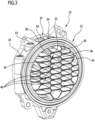
- the through-channels of the melting body have an inlet section facing the melting chamber, wherein the inlet sections form a honeycomb structure.
- the adhesive material introduced into the melting chamber can be pressed against the honeycomb structure of the melting body by means of the pressure piston.
- the honeycomb structure faces the melting chamber and forms a large surface area, allowing for particularly effective and rapid heat transfer from the electrically heated melting body to the adhesive material. This allows the adhesive material to melt within a very short time. Furthermore, the honeycomb structure has the advantage that the melting body can be easily cleaned.
- the honeycomb structure has a plurality of polygonal cells, each forming an entrance section of a through-channel and separated from each other by partition walls. Heat transfer from the heated melt body to the adhesive material can occur via the partition walls.
- the partition walls can have flat surfaces, at least in some areas, without recesses or undercuts. This reduces the risk of adhesive residues forming within the honeycomb structure.
- the hexagonal cells each have two opposite and parallel long sides which are integrally connected to one another via two pairs of narrow sides aligned at an angle to one another, the long sides being longer than the narrow sides.
- the two pairs of narrow sides are designed identically and that the two long sides are designed identically.
- the long sides are at least twice as long as the short sides.
- each of the polygonal cells of the honeycomb structure transitions continuously in the feed direction into a round, in particular circular, cross-sectional exit section of a through-channel facing away from the melting chamber.
- each cell of the honeycomb structure is adjoined by a round, cross-sectional exit section of a through-channel, with the transition from the cells to the round exit sections being continuous.
- the through-channels thus have no steps or recesses where residues of adhesive material could form and complicate cleaning of the melting body.
- the polygonal cells of the honeycomb structure taper continuously in the feed direction.
- the flow cross-section of the polygonal cells continuously decreases in the feed direction. This results in a continuous increase in the flow velocity of the adhesive material. This counteracts the formation of so-called dead spots within the cells, where the flow velocity drops to zero. Such dead spots could lead to thermal decomposition or hardening of the adhesive material, which could result in the formation of adhesive residues within the cells.
- exit sections of the through-channels which have a round cross-section, especially a circular cross-section, taper continuously in the feed direction. This leads to a continuous reduction in the flow cross-sections in the area of the exit sections and thus to an increasing flow velocity of the adhesive material in the exit sections. This counteracts the formation of adhesive residues in the exit sections.
- FIG. 1 An adhesive application system 12 of the edge banding machine is shown schematically.
- the adhesive melting device 10 is connected to the adhesive application system 12.
- an adhesive material can be melted, this will be explained in more detail below, and by means of the adhesive application system 12, the molten adhesive material can be applied with the aid of a nozzle body 14 to a longitudinal side 16 of a workpiece 18, which is glued with the aid of known and therefore in the drawing not shown transport elements, for example with the aid of transport rollers or transport chains, in a transport direction 20.
- transport elements for example with the aid of transport rollers or transport chains
- the adhesive melting device 10 has a melting chamber 22 into which the adhesive material to be melted can be introduced.
- the adhesive material to be melted can be configured, for example, in the form of an adhesive cartridge or in the form of adhesive granules.
- the adhesive melting device 10 also has a melting device 24 and an outlet body 25.
- the melting device 24 is in the Figures 2 to 6 shown schematically.
- Figure 2 also schematically shows the outlet body 25.
- the adhesive material introduced into the melting chamber 22 can be melted, and with the aid of the outlet body 25, the molten adhesive material can be fed into the adhesive application system 12.
- the outlet body 25 forms an interface between the melting device 24 and the adhesive application system 12.
- the adhesive melting device 10 has a pressure piston 26, which can be moved in a feed direction 30 by means of a feed unit 28. With the help of the pressure piston 26, the adhesive material introduced into the melting chamber 22 can be pressed against the melting device 24.
- the feed unit 28 can be configured, for example, as a piston-cylinder unit or, for example, as an electric motor. Such feed units 28 are known to those skilled in the art.
- the melting device 24 has a melting body 32 and a collecting body 34, which are arranged one behind the other in the feed direction 30.
- the outlet body 25 is arranged behind the collecting body 34. This is Figure 2 clearly.
- the melting body 32 has a plurality of through-channels 38 that extend in the feed direction 30 and each have an inlet section 40 facing the melting chamber 22 and an outlet section 42 facing away from the melting chamber 22.
- the inlet sections 40 as a whole, form a honeycomb structure 44 facing the melting chamber 22.
- the honeycomb structure 44 has a plurality of polygonal cells 46, each forming an inlet section 40 of a through-channel 38 and separated from one another by partition walls 48. In the feed direction 30, each cell 46 is adjoined by an outlet section 42 of a through-channel 38, which extends to a flat rear side 50 of the melt body 32.
- the cells 46 are hexagonal in shape. They have two opposing and parallel longitudinal sides 52, 54, which are integrally connected to one another via a first pair of narrow sides 56, 58 and a second pair of narrow sides 60, 62, wherein the narrow sides 56, 58 are arranged at an angle to one another and wherein the narrow sides 60, 62 are also arranged at an angle to one another.
- the longitudinal sides 52, 54 are significantly longer than the narrow sides 56, 58, 60, 62. In the illustrated embodiment, the longitudinal sides 52, 54 are more than twice as long as the narrow sides 56, 58, 60, 62.
- the cross sections of the outlet sections 42 of the through-channels 38 are round; in the illustrated embodiment, they are circular. Both the inlet sections 40 in the form of the cells 46 and the adjoining outlet sections 42 taper continuously in the feed direction 30, with the transition from the cells 46 to the outlet sections 42 also occurring continuously.
- the flow cross section of the through-channels 38 decreases in the feed direction 30. continuously. This is particularly evident from Figure 5 This decreases significantly.
- the decreasing flow cross-section results in the flow velocity of the adhesive material continuously increasing with increasing distance from the melting chamber 22. This counteracts the risk of so-called dead spots forming within the through-channels 38, where the flow velocity drops to zero and where thermal decomposition or curing of the adhesive material could occur. The risk of adhesive residues forming within the through-channels 38 is therefore very low.
- the melting body 32 can be heated electrically.
- it has several cylindrical recesses 64 arranged between the outlet sections 42 of the through-channels 38, each of which can accommodate an electric heating cartridge.
- Such heating cartridges are known per se to those skilled in the art and are therefore not shown in the drawings for the sake of clarity.
- the honeycomb structure 44 enables rapid and effective heat transfer from the electrically heated melting body 32 to the adhesive material.
- the adhesive material can therefore be melted within a short time.
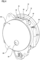
- the through-channels 38 extend to the rear side 50 of the melting body 32.
- the rear side 50 is flat, and the collecting body 34 rests against the rear side 50.
- the collecting body 34 forms a collecting plate 66 and has a plurality of collecting channels 68, 70, 72, 74, 76, which are designed in the form of depressions and into which a plurality of through-channels 38 each open. Via the collecting channels 68, 70, 72, 74, 76, the molten adhesive material can flow from the through-channels 38 to an outlet region 78 of the collecting body 34.
- the flow cross-section of the collecting channels 68, 70, 72, 74, 76 increases in the direction of the outlet area 78.
- the collecting channels 68, 70, 72, 74, 76 widen and/or deepen as they approach the outlet area 78. This is particularly evident from Figure 6
- the increasing flow cross-section of the collecting channels 68, 70, 72, 74, 76 toward the outlet area 78 allows the intake of an increasing amount of molten adhesive material, which is fed to the collecting channels 68, 70, 72, 74, 76 via the through-channels 38, while the flow velocity of the adhesive material within the collecting channels 68, 70, 72, 74, 76 remains virtually unchanged despite the increasing amount of adhesive material.
- the flow behavior of the adhesive material is therefore not impaired by the fact that several through-channels 38 open into each collecting channel.
- the collecting plate 66 has a flat front side 79 facing the melting body 32 and a flat rear side 80 facing away from the melting body 32.
- the collecting channels 68, 70, 72, 74, 76 are arranged in the form of recesses on the front side 79.
- the rear side 80 is aligned parallel to the front side 79. With its rear side 80, the collecting plate 66 rests against a flat front side 82 of the outlet body 25, which has an outlet opening 84 aligned with the outlet region 78 of the collecting body 34, through which the molten adhesive material can be fed into the adhesive application system 12.
- the adhesive application system 12 has a connecting channel 86, which adjoins the outlet opening 84 and via which the molten adhesive material can be fed to the nozzle body 14.
- the adhesive material can be melted within a short time and fed to the adhesive application system 12.
- the melting device 24 can be easily cleaned.
- the melting body 32, the collecting body 34, and the outlet body 25 are detachably connected to one another.
Landscapes
- Adhesives Or Adhesive Processes (AREA)
Claims (14)
- Dispositif de fusion de colle pour une plaqueuse de chants, dans lequel le dispositif de fusion de colle (10) présente une chambre de fusion (22) permettant d'accueillir de la matière adhésive à fondre, un organe de fusion (24) avec un corps de fusion (32) pouvant être chauffé électriquement et permettant de faire fondre la matière adhésive et un piston de pression (26) pouvant être déplacé dans une direction d'avancée (30) et permettant de presser la matière adhésive se trouvant dans la chambre de fusion (22) contre le corps de fusion (32), et dans lequel le corps de fusion (32) présente une pluralité de canaux de passage (38) qui s'étendent dans la direction d'avancée (30), et dans lequel l'organe de fusion (24) présente un corps collecteur (34) qui se raccorde au corps de fusion (32) dans la direction d'avancée (30) et qui peut être relié de manière amovible au corps de fusion (32), dans lequel le corps collecteur (34) présente plusieurs canaux collecteurs (68, 70, 72, 74, 76) dans lesquels débouchent les canaux de passage (38) du corps de fusion (32) et qui guident la matière adhésive fondue vers une région de sortie (78) du corps collecteur (34), caractérisé en ce que plusieurs canaux de passage (38) débouchent dans les canaux collecteurs (68, 70, 72, 74, 76) de manière successive en direction de la région de sortie (78) et la section transversale d'écoulement des canaux collecteurs (68, 70, 72, 74, 76) s'élargit en direction de la région de sortie (78).
- Dispositif de fusion de colle selon la revendication 1, caractérisé en ce que les canaux collecteurs (68, 70, 72, 74, 76) présentent une largeur et/ou une profondeur croissante en direction de la région de sortie (78).
- Dispositif de fusion de colle selon la revendication 2, caractérisé en ce que la largeur et/ou la profondeur d'au moins l'un des canaux collecteurs (68, 70, 72, 74, 76) augmente de manière continue sur toute sa longueur.
- Dispositif de fusion de colle selon l'une quelconque des revendications précédentes, caractérisé en ce que le corps collecteur (34) forme une plaque collectrice (66) qui présente une face avant (79) tournée vers le corps de fusion (32) et une face arrière (80) opposée au corps de fusion (32), dans lequel les canaux collecteurs (68, 70, 72, 74, 76) sont agencés sous la forme de cavités sur la face avant (79).
- Dispositif de fusion de colle selon l'une quelconque des revendications précédentes, caractérisé en ce que le dispositif de fusion de colle (10) présente un corps de sortie (25), dans lequel l'organe de fusion (24) peut être relié au corps de sortie (25), dans lequel le corps collecteur (34) est agencé entre le corps de fusion (32) et le corps de sortie (25), et dans lequel le corps de sortie (25) présente une ouverture de sortie (84) destinée à la matière adhésive fondue et orientée de manière alignée par rapport à la région de sortie (78) du corps collecteur (34).
- Dispositif de fusion de colle selon l'une quelconque des revendications précédentes, caractérisé en ce que les canaux de passage (38) du corps de fusion (32) présentent une section d'entrée (40) tournée vers la chambre de fusion (22), dans lequel les sections d'entrée (40) forment une structure en nid d'abeilles (44).
- Dispositif de fusion de colle selon la revendication 6, caractérisé en ce que la structure en nid d'abeilles (44) présente une pluralité de cellules polygonales (46) qui forment respectivement une section d'entrée (40) d'un canal de passage (38) et qui sont séparées les unes des autres par des parois de séparation (48).
- Dispositif de fusion de colle selon la revendication 7, caractérisé en ce qu'au moins certaines des cellules (46) sont de forme hexagonale.
- Dispositif de fusion de colle selon la revendication 8, caractérisé en ce que les cellules hexagonales (46) présentent respectivement deux côtés longitudinaux (52, 54) opposés l'un à l'autre et orientés parallèlement l'un à l'autre, qui sont reliés l'un à l'autre de manière solidaire par deux paires de côtés étroits (56, 58 ; 60, 62) orientés selon un angle l'un par rapport à l'autre, dans lequel les côtés longitudinaux (52, 54) sont plus longs que les côtés étroits (56, 58, 60, 62).
- Dispositif de fusion de colle selon la revendication 9, caractérisé en ce que les côtés longitudinaux (52, 54) sont au moins deux fois plus longs que les côtés étroits (56, 58, 60, 62).
- Dispositif de fusion de colle selon l'une quelconque des revendications 7 à 10, caractérisé en ce que chacune des cellules polygonales (46) de la structure en nid d'abeilles (44) se transforme de manière continue dans la direction d'avancée (30) en une section de sortie (42), circulaire en coupe transversale, d'un canal de passage (38).
- Dispositif de fusion de colle selon la revendication 11, caractérisé en ce que les cellules polygonales (46) se rétrécissent de manière continue dans la direction d'avancée (30).
- Dispositif de fusion de colle selon la revendication 11 ou 12, caractérisé en ce que les sections de sortie (42), circulaires en coupe transversale, des canaux de passage (38) se rétrécissent de manière continue dans la direction d'avancée (30).
- Dispositif de fusion de colle selon l'une quelconque des revendications précédentes, caractérisé en ce que les canaux de passage (38) se rétrécissent de manière continue sur toute leur longueur.
Priority Applications (1)
| Application Number | Priority Date | Filing Date | Title |
|---|---|---|---|
| EP21193077.1A EP4140599B1 (fr) | 2021-08-25 | 2021-08-25 | Dispositif de fusion d'adhésif pour une machine à plaquer des chants |
Applications Claiming Priority (1)
| Application Number | Priority Date | Filing Date | Title |
|---|---|---|---|
| EP21193077.1A EP4140599B1 (fr) | 2021-08-25 | 2021-08-25 | Dispositif de fusion d'adhésif pour une machine à plaquer des chants |
Publications (2)
| Publication Number | Publication Date |
|---|---|
| EP4140599A1 EP4140599A1 (fr) | 2023-03-01 |
| EP4140599B1 true EP4140599B1 (fr) | 2025-06-25 |
Family
ID=77499753
Family Applications (1)
| Application Number | Title | Priority Date | Filing Date |
|---|---|---|---|
| EP21193077.1A Active EP4140599B1 (fr) | 2021-08-25 | 2021-08-25 | Dispositif de fusion d'adhésif pour une machine à plaquer des chants |
Country Status (1)
| Country | Link |
|---|---|
| EP (1) | EP4140599B1 (fr) |
Family Cites Families (7)
| Publication number | Priority date | Publication date | Assignee | Title |
|---|---|---|---|---|
| DE3109369C2 (de) * | 1981-03-12 | 1984-01-12 | Reich Spezialmaschinen GmbH, 7440 Nürtingen | Schmelz- und Auftragsvorrichtung für Schmelzkleber |
| EP0342254A1 (fr) * | 1988-05-18 | 1989-11-23 | Nordson Corporation | Dispositif pour fondre des matières thermoplastiques, en particulier des adhésifs |
| US7626143B2 (en) * | 2005-02-17 | 2009-12-01 | Scott Richard Miller | Apparatus and method for processing hot melt adhesives |
| TW201511846A (zh) * | 2013-09-17 | 2015-04-01 | Technos Co Ltd | 熱熔膠槍 |
| DE102017111013A1 (de) | 2017-05-19 | 2018-11-22 | Holz-Her Gmbh | Kleberauftragsvorrichtung |
| CN108160411B (zh) * | 2018-02-06 | 2024-01-30 | 北京延锋北汽汽车内饰件有限公司 | 一种标准桶热熔胶处理设备 |
| IT201800010342A1 (it) * | 2018-11-15 | 2020-05-15 | Zanin Nello S R L | Dispositivo fusore e procedimento per utilizzarlo |
-
2021
- 2021-08-25 EP EP21193077.1A patent/EP4140599B1/fr active Active
Also Published As
| Publication number | Publication date |
|---|---|
| EP4140599A1 (fr) | 2023-03-01 |
Similar Documents
| Publication | Publication Date | Title |
|---|---|---|
| EP0143936B1 (fr) | Dispositif pour joindre ou comprimer des conducteurs électriques | |
| DE3034068C2 (de) | Extrusionswerkzeug für die Herstellung von honigwaben-ähnlichen Profilen, insbesondere als Katalysatorträger, sowie Verfahren zu dessen Herstellung | |
| DE2522106C3 (de) | Vorrichtung zum kontinuierlichen Mischen fließfähiger Stoffe und Verfahren zum Herstellen eines Mischeinsatzes | |
| EP0052359B1 (fr) | Presse fonctionnant en continu | |
| DE2432541A1 (de) | Verfahren und vorrichtung zur herstellung von verbundprofilen od.dgl. | |
| EP3676079A1 (fr) | Composant chauffant de soudage par contact et automate de soudage | |
| DE3020009A1 (de) | Vorrichtung fuer die herstellung von beuteln aus einer kunststoffolien-schlauchbahn | |
| EP2464473B1 (fr) | Procédé pour l'ébavurage multibrin de brins de fil et dispositif correspondant | |
| EP4140599B1 (fr) | Dispositif de fusion d'adhésif pour une machine à plaquer des chants | |
| DE3224670C2 (fr) | ||
| EP4140598B1 (fr) | Dispositif de fusion d'adhésif pour une machine à plaquer des chants | |
| DE69016543T2 (de) | Fussbodenpaneel und Vorrichtung zu dessen Herstellung. | |
| EP1625898B1 (fr) | Dispositif pour la fabrication de tubes | |
| EP1488895A2 (fr) | Lame de coupe ainsi que procédé pour sa fabrication | |
| EP4255720B1 (fr) | Élément d'usinage avec élément de structure | |
| DE3613071C2 (fr) | ||
| DE2415205C3 (de) | Verfahren zum Brikettieren von Metallspänen, Metallpellets und Metallpulvern auf Walzenpressen | |
| EP3548204B1 (fr) | Buse de coulée | |
| DE3528019C2 (fr) | ||
| AT506807B1 (de) | Biegewerkzeug für eine blechbiegepresse sowie verfahren zu dessen herstellung | |
| DE19855073B4 (de) | Vorrichtung und Verfahren zur Herstellung einer Verbindung zweier Bauteile durch Nahtschweißen mittels eines Laserstrahls | |
| DE8131528U1 (de) | Vorrichtung zum nietartigen Verbinden von Blechen | |
| DE1246904C2 (de) | Verfahren zum kontinuierlichen stumpfen verschweissen benachbarter laengskanten zweier flacher, breiter, in einer ebene gefuehrter blechstreifen | |
| EP1818128B1 (fr) | Méthode et dispositif de soudage sous pression de pièces ayant une bride de hauteur minimale, en particulier des tôles ou des profiles | |
| EP3409435B1 (fr) | Dispositif de pressage pour la fabrication de tronçon de bois de bois |
Legal Events
| Date | Code | Title | Description |
|---|---|---|---|
| PUAI | Public reference made under article 153(3) epc to a published international application that has entered the european phase |
Free format text: ORIGINAL CODE: 0009012 |
|
| STAA | Information on the status of an ep patent application or granted ep patent |
Free format text: STATUS: THE APPLICATION HAS BEEN PUBLISHED |
|
| AK | Designated contracting states |
Kind code of ref document: A1 Designated state(s): AL AT BE BG CH CY CZ DE DK EE ES FI FR GB GR HR HU IE IS IT LI LT LU LV MC MK MT NL NO PL PT RO RS SE SI SK SM TR |
|
| P01 | Opt-out of the competence of the unified patent court (upc) registered |
Effective date: 20230521 |
|
| STAA | Information on the status of an ep patent application or granted ep patent |
Free format text: STATUS: REQUEST FOR EXAMINATION WAS MADE |
|
| 17P | Request for examination filed |
Effective date: 20230831 |
|
| RBV | Designated contracting states (corrected) |
Designated state(s): AL AT BE BG CH CY CZ DE DK EE ES FI FR GB GR HR HU IE IS IT LI LT LU LV MC MK MT NL NO PL PT RO RS SE SI SK SM TR |
|
| RIC1 | Information provided on ipc code assigned before grant |
Ipc: B05C 11/10 20060101ALI20241219BHEP Ipc: B05C 5/02 20060101AFI20241219BHEP |
|
| GRAP | Despatch of communication of intention to grant a patent |
Free format text: ORIGINAL CODE: EPIDOSNIGR1 |
|
| STAA | Information on the status of an ep patent application or granted ep patent |
Free format text: STATUS: GRANT OF PATENT IS INTENDED |
|
| INTG | Intention to grant announced |
Effective date: 20250206 |
|
| GRAS | Grant fee paid |
Free format text: ORIGINAL CODE: EPIDOSNIGR3 |
|
| GRAA | (expected) grant |
Free format text: ORIGINAL CODE: 0009210 |
|
| STAA | Information on the status of an ep patent application or granted ep patent |
Free format text: STATUS: THE PATENT HAS BEEN GRANTED |
|
| AK | Designated contracting states |
Kind code of ref document: B1 Designated state(s): AL AT BE BG CH CY CZ DE DK EE ES FI FR GB GR HR HU IE IS IT LI LT LU LV MC MK MT NL NO PL PT RO RS SE SI SK SM TR |
|
| REG | Reference to a national code |
Ref country code: GB Ref legal event code: FG4D Free format text: NOT ENGLISH |
|
| REG | Reference to a national code |
Ref country code: CH Ref legal event code: EP |
|
| REG | Reference to a national code |
Ref country code: DE Ref legal event code: R096 Ref document number: 502021007826 Country of ref document: DE |
|
| REG | Reference to a national code |
Ref country code: CH Ref legal event code: EP |
|
| REG | Reference to a national code |
Ref country code: IE Ref legal event code: FG4D Free format text: LANGUAGE OF EP DOCUMENT: GERMAN |
|
| PG25 | Lapsed in a contracting state [announced via postgrant information from national office to epo] |
Ref country code: FI Free format text: LAPSE BECAUSE OF FAILURE TO SUBMIT A TRANSLATION OF THE DESCRIPTION OR TO PAY THE FEE WITHIN THE PRESCRIBED TIME-LIMIT Effective date: 20250625 |
|
| PGFP | Annual fee paid to national office [announced via postgrant information from national office to epo] |
Ref country code: DE Payment date: 20250822 Year of fee payment: 5 |
|
| REG | Reference to a national code |
Ref country code: LT Ref legal event code: MG9D |
|
| PG25 | Lapsed in a contracting state [announced via postgrant information from national office to epo] |
Ref country code: GR Free format text: LAPSE BECAUSE OF FAILURE TO SUBMIT A TRANSLATION OF THE DESCRIPTION OR TO PAY THE FEE WITHIN THE PRESCRIBED TIME-LIMIT Effective date: 20250926 Ref country code: NO Free format text: LAPSE BECAUSE OF FAILURE TO SUBMIT A TRANSLATION OF THE DESCRIPTION OR TO PAY THE FEE WITHIN THE PRESCRIBED TIME-LIMIT Effective date: 20250925 |
|
| PGFP | Annual fee paid to national office [announced via postgrant information from national office to epo] |
Ref country code: TR Payment date: 20250821 Year of fee payment: 5 |
|
| PG25 | Lapsed in a contracting state [announced via postgrant information from national office to epo] |
Ref country code: BG Free format text: LAPSE BECAUSE OF FAILURE TO SUBMIT A TRANSLATION OF THE DESCRIPTION OR TO PAY THE FEE WITHIN THE PRESCRIBED TIME-LIMIT Effective date: 20250625 |
|
| PG25 | Lapsed in a contracting state [announced via postgrant information from national office to epo] |
Ref country code: HR Free format text: LAPSE BECAUSE OF FAILURE TO SUBMIT A TRANSLATION OF THE DESCRIPTION OR TO PAY THE FEE WITHIN THE PRESCRIBED TIME-LIMIT Effective date: 20250625 |
|
| PGFP | Annual fee paid to national office [announced via postgrant information from national office to epo] |
Ref country code: AT Payment date: 20251020 Year of fee payment: 5 |
|
| PG25 | Lapsed in a contracting state [announced via postgrant information from national office to epo] |
Ref country code: RS Free format text: LAPSE BECAUSE OF FAILURE TO SUBMIT A TRANSLATION OF THE DESCRIPTION OR TO PAY THE FEE WITHIN THE PRESCRIBED TIME-LIMIT Effective date: 20250925 |
|
| PG25 | Lapsed in a contracting state [announced via postgrant information from national office to epo] |
Ref country code: LV Free format text: LAPSE BECAUSE OF FAILURE TO SUBMIT A TRANSLATION OF THE DESCRIPTION OR TO PAY THE FEE WITHIN THE PRESCRIBED TIME-LIMIT Effective date: 20250625 |
|
| REG | Reference to a national code |
Ref country code: NL Ref legal event code: MP Effective date: 20250625 |
|
| PG25 | Lapsed in a contracting state [announced via postgrant information from national office to epo] |
Ref country code: NL Free format text: LAPSE BECAUSE OF FAILURE TO SUBMIT A TRANSLATION OF THE DESCRIPTION OR TO PAY THE FEE WITHIN THE PRESCRIBED TIME-LIMIT Effective date: 20250625 |
|
| PG25 | Lapsed in a contracting state [announced via postgrant information from national office to epo] |
Ref country code: PT Free format text: LAPSE BECAUSE OF FAILURE TO SUBMIT A TRANSLATION OF THE DESCRIPTION OR TO PAY THE FEE WITHIN THE PRESCRIBED TIME-LIMIT Effective date: 20251027 |
|
| PG25 | Lapsed in a contracting state [announced via postgrant information from national office to epo] |
Ref country code: IS Free format text: LAPSE BECAUSE OF FAILURE TO SUBMIT A TRANSLATION OF THE DESCRIPTION OR TO PAY THE FEE WITHIN THE PRESCRIBED TIME-LIMIT Effective date: 20251025 |
|
| PG25 | Lapsed in a contracting state [announced via postgrant information from national office to epo] |
Ref country code: SM Free format text: LAPSE BECAUSE OF FAILURE TO SUBMIT A TRANSLATION OF THE DESCRIPTION OR TO PAY THE FEE WITHIN THE PRESCRIBED TIME-LIMIT Effective date: 20250625 |
|
| PG25 | Lapsed in a contracting state [announced via postgrant information from national office to epo] |
Ref country code: CZ Free format text: LAPSE BECAUSE OF FAILURE TO SUBMIT A TRANSLATION OF THE DESCRIPTION OR TO PAY THE FEE WITHIN THE PRESCRIBED TIME-LIMIT Effective date: 20250625 |
|
| PG25 | Lapsed in a contracting state [announced via postgrant information from national office to epo] |
Ref country code: PL Free format text: LAPSE BECAUSE OF FAILURE TO SUBMIT A TRANSLATION OF THE DESCRIPTION OR TO PAY THE FEE WITHIN THE PRESCRIBED TIME-LIMIT Effective date: 20250625 |
|
| PG25 | Lapsed in a contracting state [announced via postgrant information from national office to epo] |
Ref country code: EE Free format text: LAPSE BECAUSE OF FAILURE TO SUBMIT A TRANSLATION OF THE DESCRIPTION OR TO PAY THE FEE WITHIN THE PRESCRIBED TIME-LIMIT Effective date: 20250625 |
|
| PG25 | Lapsed in a contracting state [announced via postgrant information from national office to epo] |
Ref country code: SK Free format text: LAPSE BECAUSE OF FAILURE TO SUBMIT A TRANSLATION OF THE DESCRIPTION OR TO PAY THE FEE WITHIN THE PRESCRIBED TIME-LIMIT Effective date: 20250625 |
|
| PG25 | Lapsed in a contracting state [announced via postgrant information from national office to epo] |
Ref country code: ES Free format text: LAPSE BECAUSE OF FAILURE TO SUBMIT A TRANSLATION OF THE DESCRIPTION OR TO PAY THE FEE WITHIN THE PRESCRIBED TIME-LIMIT Effective date: 20250625 |
|
| PG25 | Lapsed in a contracting state [announced via postgrant information from national office to epo] |
Ref country code: RO Free format text: LAPSE BECAUSE OF FAILURE TO SUBMIT A TRANSLATION OF THE DESCRIPTION OR TO PAY THE FEE WITHIN THE PRESCRIBED TIME-LIMIT Effective date: 20250625 |
|
| REG | Reference to a national code |
Ref country code: CH Ref legal event code: H13 Free format text: ST27 STATUS EVENT CODE: U-0-0-H10-H13 (AS PROVIDED BY THE NATIONAL OFFICE) Effective date: 20260324 |
|
| PG25 | Lapsed in a contracting state [announced via postgrant information from national office to epo] |
Ref country code: MC Free format text: LAPSE BECAUSE OF FAILURE TO SUBMIT A TRANSLATION OF THE DESCRIPTION OR TO PAY THE FEE WITHIN THE PRESCRIBED TIME-LIMIT Effective date: 20250625 |
|
| PG25 | Lapsed in a contracting state [announced via postgrant information from national office to epo] |
Ref country code: DK Free format text: LAPSE BECAUSE OF FAILURE TO SUBMIT A TRANSLATION OF THE DESCRIPTION OR TO PAY THE FEE WITHIN THE PRESCRIBED TIME-LIMIT Effective date: 20250625 |
|
| PG25 | Lapsed in a contracting state [announced via postgrant information from national office to epo] |
Ref country code: LU Free format text: LAPSE BECAUSE OF NON-PAYMENT OF DUE FEES Effective date: 20250825 |