EP4140686B1 - Procédé de combinaison de mousse à âme renforcée - Google Patents
Procédé de combinaison de mousse à âme renforcée Download PDFInfo
- Publication number
- EP4140686B1 EP4140686B1 EP21213970.3A EP21213970A EP4140686B1 EP 4140686 B1 EP4140686 B1 EP 4140686B1 EP 21213970 A EP21213970 A EP 21213970A EP 4140686 B1 EP4140686 B1 EP 4140686B1
- Authority
- EP
- European Patent Office
- Prior art keywords
- reinforced core
- mold
- chamber
- foam
- combining
- Prior art date
- Legal status (The legal status is an assumption and is not a legal conclusion. Google has not performed a legal analysis and makes no representation as to the accuracy of the status listed.)
- Active
Links
Images

Classifications
-
- B—PERFORMING OPERATIONS; TRANSPORTING
- B29—WORKING OF PLASTICS; WORKING OF SUBSTANCES IN A PLASTIC STATE IN GENERAL
- B29D—PRODUCING PARTICULAR ARTICLES FROM PLASTICS OR FROM SUBSTANCES IN A PLASTIC STATE
- B29D35/00—Producing footwear
- B29D35/0054—Producing footwear by compression moulding, vulcanising or the like; Apparatus therefor
- B29D35/0063—Moulds
-
- A—HUMAN NECESSITIES
- A43—FOOTWEAR
- A43B—CHARACTERISTIC FEATURES OF FOOTWEAR; PARTS OF FOOTWEAR
- A43B13/00—Soles; Sole-and-heel integral units
- A43B13/02—Soles; Sole-and-heel integral units characterised by the material
- A43B13/12—Soles with several layers of different materials
- A43B13/125—Soles with several layers of different materials characterised by the midsole or middle layer
- A43B13/127—Soles with several layers of different materials characterised by the midsole or middle layer the midsole being multilayer
-
- A—HUMAN NECESSITIES
- A43—FOOTWEAR
- A43B—CHARACTERISTIC FEATURES OF FOOTWEAR; PARTS OF FOOTWEAR
- A43B13/00—Soles; Sole-and-heel integral units
- A43B13/14—Soles; Sole-and-heel integral units characterised by the constructive form
- A43B13/141—Soles; Sole-and-heel integral units characterised by the constructive form with a part of the sole being flexible, e.g. permitting articulation or torsion
-
- A—HUMAN NECESSITIES
- A43—FOOTWEAR
- A43B—CHARACTERISTIC FEATURES OF FOOTWEAR; PARTS OF FOOTWEAR
- A43B13/00—Soles; Sole-and-heel integral units
- A43B13/14—Soles; Sole-and-heel integral units characterised by the constructive form
- A43B13/18—Resilient soles
- A43B13/187—Resiliency achieved by the features of the material, e.g. foam, non liquid materials
-
- B—PERFORMING OPERATIONS; TRANSPORTING
- B29—WORKING OF PLASTICS; WORKING OF SUBSTANCES IN A PLASTIC STATE IN GENERAL
- B29C—SHAPING OR JOINING OF PLASTICS; SHAPING OF MATERIAL IN A PLASTIC STATE, NOT OTHERWISE PROVIDED FOR; AFTER-TREATMENT OF THE SHAPED PRODUCTS, e.g. REPAIRING
- B29C44/00—Shaping by internal pressure generated in the material, e.g. swelling or foaming ; Producing porous or cellular expanded plastics articles
- B29C44/02—Shaping by internal pressure generated in the material, e.g. swelling or foaming ; Producing porous or cellular expanded plastics articles for articles of definite length, i.e. discrete articles
- B29C44/12—Incorporating or moulding on preformed parts, e.g. inserts or reinforcements
- B29C44/1214—Anchoring by foaming into a preformed part, e.g. by penetrating through holes
-
- B—PERFORMING OPERATIONS; TRANSPORTING
- B29—WORKING OF PLASTICS; WORKING OF SUBSTANCES IN A PLASTIC STATE IN GENERAL
- B29C—SHAPING OR JOINING OF PLASTICS; SHAPING OF MATERIAL IN A PLASTIC STATE, NOT OTHERWISE PROVIDED FOR; AFTER-TREATMENT OF THE SHAPED PRODUCTS, e.g. REPAIRING
- B29C44/00—Shaping by internal pressure generated in the material, e.g. swelling or foaming ; Producing porous or cellular expanded plastics articles
- B29C44/02—Shaping by internal pressure generated in the material, e.g. swelling or foaming ; Producing porous or cellular expanded plastics articles for articles of definite length, i.e. discrete articles
- B29C44/12—Incorporating or moulding on preformed parts, e.g. inserts or reinforcements
- B29C44/1266—Incorporating or moulding on preformed parts, e.g. inserts or reinforcements the preformed part being completely encapsulated, e.g. for packaging purposes or as reinforcement
-
- B—PERFORMING OPERATIONS; TRANSPORTING
- B29—WORKING OF PLASTICS; WORKING OF SUBSTANCES IN A PLASTIC STATE IN GENERAL
- B29D—PRODUCING PARTICULAR ARTICLES FROM PLASTICS OR FROM SUBSTANCES IN A PLASTIC STATE
- B29D35/00—Producing footwear
- B29D35/12—Producing parts thereof, e.g. soles, heels, uppers, by a moulding technique
- B29D35/122—Soles
-
- B—PERFORMING OPERATIONS; TRANSPORTING
- B29—WORKING OF PLASTICS; WORKING OF SUBSTANCES IN A PLASTIC STATE IN GENERAL
- B29D—PRODUCING PARTICULAR ARTICLES FROM PLASTICS OR FROM SUBSTANCES IN A PLASTIC STATE
- B29D35/00—Producing footwear
- B29D35/12—Producing parts thereof, e.g. soles, heels, uppers, by a moulding technique
- B29D35/128—Moulds or apparatus therefor
-
- B—PERFORMING OPERATIONS; TRANSPORTING
- B29—WORKING OF PLASTICS; WORKING OF SUBSTANCES IN A PLASTIC STATE IN GENERAL
- B29L—INDEXING SCHEME ASSOCIATED WITH SUBCLASS B29C, RELATING TO PARTICULAR ARTICLES
- B29L2031/00—Other particular articles
- B29L2031/48—Wearing apparel
- B29L2031/50—Footwear, e.g. shoes or parts thereof
- B29L2031/504—Soles
Definitions
- the invention is related to polymer molding and processing technique, and more particularly to a method for combining a foam with a reinforced core.
- Document EP 1 867 455 A2 discloses a cushion body and a manufacturing method for the same.
- document DE 17 04 329 A1 a mold is described for the production of sandals from foam plastic which can be cast and hardened into a viscoplastic material.
- Document WO 01/79624 A1 describes an architectural flooring plate spaced from a concrete bottom and a method of manufacturing the same.
- a main object of the invention is to provide a method for combining a foam with a reinforced core.
- An article made by the method disclosed herein is capable of eliminating use of adhesives to complete combination between the foam and the reinforced core to further improve a bonding strength between the foam and the reinforced core.
- a combinational article of a foam and a reinforced core is formed by enclosing the sheet-like reinforced core with a plurality of perforations by the foam completely, and at the same time, the foam is also present in the perforations, between an interior of the foam and the reinforced core, the partial foam existing in the perforations is capable of connecting with the foam on two sides of the reinforced core, so that the foam is closely attached on the reinforced core to avoid the problem that the foam and the reinforced core are difficult to be combined with each other through bonding due to the absence of bonding means using adhesives or the heterogeneity between the foam and the reinforced core, which is prone to peeling off or detachment between the foam and the reinforced core, resulting in the drawbacks of poor quality and short service life.
- the method for combining the foam with the reinforced core provided by the invention is used to make the combinational article of the foam and the reinforced core.
- the reinforced core in order for the foam to form a complete enclosing on a peripheral side of the reinforced core, when molding is performed with a mold, the reinforced core has to be located in a mold chamber defined by the mold, and the peripheral side of the reinforced core and a chamber wall surrounding the mold chamber are separated from each other, and then a molten polymer raw material containing a foaming agent is filled into the mold chamber to be foamed and molded by the mold chamber.
- the polymer raw material can be synchronously foamed and molded in the perforations of the reinforced core, so that the molded foam and the reinforced core are interlaced with each other structurally and closely attached to each other to obtain a good bonding effect.
- the mold further comprises a plurality of first position protruding points formed by protruding from the chamber wall in the mold chamber in an opposite direction of gravity, and the reinforced core is placed on free ends of the first position protruding points to ensure a distance between the reinforced core and the chamber wall of the mold chamber.
- a plurality of second position protruding points protrude on the chamber wall of the mold chamber on another side relative to the side with the first position protruding points, and a distance between the free ends of the first position protruding points and free ends of the second position protruding points is equal to a thickness of a sheet of the reinforced core, so that the reinforced core can be sandwiched and fixed between the first position protruding points and the second position protruding points.
- Each of the first position protruding points and each of the second position protruding points can be a fixed type pin or a retractable movable pin.
- an unfoamed embryo pre-molded with a raw material having a same matrix as that of the polymer raw material may be placed in the mold chamber, and a surface of the embryo is used to place and support the reinforced core, so that the reinforced core is separated from the chamber wall of the mold chamber to obtain the same positioning effect achieved by adopting the above-mentioned position protruding points, and when the polymer raw material is foamed and molded, a chemical bond can be formed between the polymer raw material and the embryo under the condition of the same matrix to obtain a good combination structure.
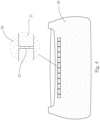
- a reinforced core 20 used is as shown in FIG. 1 , the reinforced core 20 has a thin sheet 21 and a plurality of perforations 22 penetrating through the sheet 21, wherein, in order to tackle the drawback of poor strength of the reinforced core 20 due to the reinforced core 20 being a reinforced foam with an elasticity provided by a foamed structure, a material of the sheet 21 can be selected according to actual requirements, such as an article that is non-foamed, substantially non-foamed, or an article still has the required mechanical strength and elasticity after foaming and made of thermoplastic polymer material, thermosetting polymer material, elastic polymer material, carbon fiber or other composite materials, so that the reinforced core 20 has a higher hardness than ordinary foam to meet an object of reinforcement.
- a hole diameter size of the perforations 22 is limited to a range that does not greatly affect a strength of the sheet 21.
- the perforations 22 only need to be small holes, that is, big enough for entry of a polymer raw material, and can also meet the requirements of the invention.
- the perforations 22 can also be set as holes with different hole diameters to be disposed on different areas of the sheet 21 according to required characteristics of the reinforced core 20 for specific application or usage of a molded article, such as making the reinforced core 20 easy to bend and deform structurally or maintaining the highest possible strength.
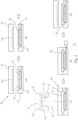
- Implementation of the method 10 for combining the foam with the reinforced core comprises following steps.
- the mold 30 has an upper mold plate 32 which is different to a mold plate used for the claimed invention and a lower mold plate 33 that can be overlapped and connected with or separated from each other.
- the second position protruding points of the upper mold plate according to the invention are not shown.
- the upper mold plate 32 and the lower mold plate 33 are separately disposed to define mold cavities 321, 331 of the mold chamber 31 in an open state.
- the reinforced core 20 is placed into the mold cavity 331 of the lower mold plate 33 when the mold 30 is at the mold opening position, and then the upper mold plate 32 is stacked on the lower mold plate 33, so that the reinforced core 20 is accommodated in the mold chamber 31.
- a sheet surface 211 on one side, a sheet surface 212 on another side, and a peripheral edge 213 of the sheet 21 are facing a chamber wall 311 of the mold chamber 31, and are separated from the chamber wall 311 without abutting against the chamber wall 311.
- an appropriate support structure can be provided between the reinforced core 20 and the chamber wall 311 of the mold chamber 31 in the direction of gravity, and the reinforced core 20 can be supported on the appropriate support structure.
- three protruding points 34 of pins, posts or protrusions arranged in a triangular configuration and with a height smaller than the mold chamber 31 can be protruded from a bottom surface of the mold cavity 331 of the lower mold plate 33, and upper free ends of the protruding points 34 are used to place and support the sheet 21 of the reinforced core 20 to maintain a separation state between the reinforced core 20 and the bottom surface of the mold cavity 331 of the lower mold plate 33.
- the protruding points 34 serving as supporting elements can be fixed on the lower mold plate 33 or movably disposed on the lower mold plate 33 for retracting, stretching or displacing.
- a preformed, non-foamed or unfoamed embryo (not shown in the figures) can be placed on the bottom surface of the mold cavity 331 of the lower mold plate 33 as a supporting element, and then the reinforced core 20 is placed on the embryo directly, so that an effect of separating the reinforced core 20 from the bottom surface of the mold cavity 331 of the lower mold plate 33 can be obtained.
- a molten polymer raw material 40 containing a foaming agent such as a supercritical fluid is filled into the mold chamber 31 through a suitable runner, so that the polymer raw material 40 is at least filled in a part of mold chamber space of the mold chamber 31 between the sheet surface 211 of the sheet 21 and the top chamber wall 311 of the mold chamber 31, and in hole spaces of the perforations 22.
- the rated polymer raw material 40 is filled in an entire space of the mold chamber 31, as shown in FIG. 2(D) ; but when the supporting technique used is the embryo, the rated polymer raw material 40 is only filled in a part of the mold chamber space of the mold chamber 31 and the hole spaces of the perforations 22.
- foaming can be performed in the mold chamber 31 and molded into a foam 50 by the mold chamber 31, and the mold 30 can be opened as shown in FIG. 2(E) to take out a finished product.
- the polymer raw material 40 located in the perforations 22 after foaming and forming can be used as a connecting structure for connecting a part of the foam 50 located outside the sheet surface 211 and the sheet surface 212 of the reinforced core 20, thereby, a close bonding effect is obtained between the reinforced core 20 and the foam 50, and a stability of bonding between the reinforced core 20 and the foam 50 is ensured.
- the embryo should contain a component that can be bonded with the polymer raw material 40, or both the embryo and the polymer raw material 40 have a same matrix; thereby, in a state of contacting with the embryo, a bond can be formed between the polymer raw material 40 located in the perforations 22, and the polymer raw material 40 located on a peripheral side of the reinforced core 20 to obtain the same effect as described above.
- a material with a same matrix as that of the foam 50 can be selected for manufacturing the sheet 21 of the reinforced core 20, for example, materials used for manufacturing both the polymer raw material 40 and the sheet 21 have to contain TPU, TPE, PU, EVA or other recyclable raw materials, so that when the combinational article is recycled, the foam 50 and the reinforced core 20 can be recycled synchronously in a same recycling process.
- an appropriate inert gas or carbon dioxide can be filled into the mold chamber 31 to form a back pressure. After a rated material filling volume is filled, the filled back pressure gas is vented instantaneously, so that the polymer raw material 40 is foamed while the back pressure disappears.
- a combinational article 11 of a foam and a reinforced core made by the above-mentioned method is structurally capable of completely enclosing the entire reinforced core 20 by using the foam 50, and at the same time, the foamed part formed in each of the perforations 22 is used as a bonding element for bridging connection to connect with a part of the foam 50 located outside the sheet surface 211 and the sheet surface 212 of the reinforced core 20, so that the combinational article 11 of the foam and the reinforced core can have an elasticity of the foam 50 and a rigidity of the reinforced core 20.
- the combinational article 11 is used as a sole, comfort level of wearing and treading stability for a user can be greatly improved.
Landscapes
- Engineering & Computer Science (AREA)
- Mechanical Engineering (AREA)
- Chemical & Material Sciences (AREA)
- Materials Engineering (AREA)
- Moulds For Moulding Plastics Or The Like (AREA)
- Injection Moulding Of Plastics Or The Like (AREA)
- Molding Of Porous Articles (AREA)
- Moulding By Coating Moulds (AREA)
- Molds, Cores, And Manufacturing Methods Thereof (AREA)
Claims (8)
- Procédé (10) de combinaison d'une mousse (50) avec une âme renforcée (20) comprenant les étapes suivantes de :adoption d'une âme renforcée (20), l'âme renforcée (20) présentant une feuille mince (21) et une pluralité de perforations (22) pénétrant à travers la feuille (21) respectivement, adoption d'un moule (30), le moule (30) présentant au moins deux plaques de moulage (32, 33), les plaques de moulage (32, 33) se déplaçant relativement l'une par rapport à l'autre entre une position de serrage de moule et une position d'ouverture de moule sous l'action d'une force externe lorsque les plaques de moulage (32, 33) sont situées en position de serrage de moule, définissant une chambre de moulage (31) avec un espace fermé entre les plaques de moulage (32, 33),positionnement de l'âme renforcée (20) dans l'espace de la chambre de moulage (31), séparant une surface de feuille (211) et une autre surface de feuille (212) sur deux côtés opposés de l'âme renforcée (20) des parois (311) de chambre sur deux côtés de la chambre de moulage (31) tournées vers les deux surfaces de feuille (211, 212) respectivement, etintroduction d'une matière première polymère fondue homologuée (40) contenant un agent moussant au moins dans une partie de l'espace de la chambre de moulage (31) et des espaces de trous des perforations (22) à expanser et mouler dans la chambre de moulage (31), dans lequel une partie de l'espace de la chambre de moulage (31) fait référence à un espace compris entre la surface de feuille (211) de l'un des côtés de l'âme renforcée (20) et la paroi (311) de chambre de l'un des côtés de la chambre de moulage (31) tournée vers la surface de feuille (211),dans lequel le moule (30) comprend en outre une pluralité de points saillants de première position formés en faisant saillie depuis la paroi (311) de chambre dans la chambre de moulage (31) dans une direction opposée à la gravité, et l'âme renforcée (20) est placée sur des extrémités libres des points saillants de première position pour garantir une distance entre l'âme renforcée (20) et la paroi (311) de chambre de la chambre de moulage (31),caractérisé en ce qu'une pluralité de points saillants de seconde position font saillie sur la paroi (311) de chambre de la chambre de moulage (31) sur un autre côté par rapport au côté avec les points saillants de première position, et une distance entre les extrémités libres des points saillants de première position et des extrémités libres des points saillants de seconde position est égale à une épaisseur d'une feuille (21) de l'âme renforcée (20), de sorte que l'âme renforcée puisse être prise en sandwich et fixée entre les points saillants de première position et les points saillants de seconde position.
- Procédé (10) de combinaison de la mousse (50) avec l'âme renforcée (20) selon la revendication 1, dans lequel la matière première polymère homologuée (40) est introduite dans tout l'espace de la chambre de moulage (31) à l'exception d'un espace où est située l'âme renforcée (20).
- Procédé (10) de combinaison de la mousse (50) avec l'âme renforcée (20) selon la revendication 1, avant que la matière première polymère (40) n'entre dans la chambre de moulage (31), disposant en outre un embryon entre l'autre surface de feuille (212) de l'âme renforcée (20) et la paroi (311) de chambre de la chambre de moulage (31) tournée vers l'autre surface de feuille (212).
- Procédé (10) de combinaison de la mousse (50) avec l'âme renforcée (20) selon la revendication 3, dans lequel la matière première polymère (40) et l'embryon comprennent respectivement une même matrice.
- Procédé (10) de combinaison de la mousse (50) avec l'âme renforcée (20) selon la revendication 3 ou 4, dans lequel l'embryon ne comprend pas d'agent moussant et est non expansé.
- Procédé (10) de combinaison de la mousse (50) avec l'âme renforcée (20) selon la revendication 1, dans lequel l'agent moussant contenu dans la matière première polymère (40) est un fluide supercritique.
- Procédé (10) de combinaison de la mousse (50) avec l'âme renforcée (20) selon la revendication 1, dans lequel un bord périphérique (213) de l'âme renforcée (20) est séparé de la paroi de chambre entourant la chambre de moulage (31).
- Procédé (10) de combinaison de la mousse (50) avec l'âme renforcée (20) selon la revendication 1, dans lequel l'âme renforcée (20) est en matière polymère thermoplastique, matière polymère thermodurcissable, matière polymère élastique ou matière composite.
Priority Applications (1)
| Application Number | Priority Date | Filing Date | Title |
|---|---|---|---|
| EP22190679.5A EP4140687B1 (fr) | 2021-08-23 | 2022-08-17 | Article et son procédé de fabrication |
Applications Claiming Priority (2)
| Application Number | Priority Date | Filing Date | Title |
|---|---|---|---|
| TW110130996 | 2021-08-23 | ||
| TW110141372 | 2021-11-05 |
Publications (3)
| Publication Number | Publication Date |
|---|---|
| EP4140686A1 EP4140686A1 (fr) | 2023-03-01 |
| EP4140686C0 EP4140686C0 (fr) | 2025-02-05 |
| EP4140686B1 true EP4140686B1 (fr) | 2025-02-05 |
Family
ID=78851021
Family Applications (1)
| Application Number | Title | Priority Date | Filing Date |
|---|---|---|---|
| EP21213970.3A Active EP4140686B1 (fr) | 2021-08-23 | 2021-12-13 | Procédé de combinaison de mousse à âme renforcée |
Country Status (5)
| Country | Link |
|---|---|
| EP (1) | EP4140686B1 (fr) |
| JP (1) | JP7212408B1 (fr) |
| KR (1) | KR20230029475A (fr) |
| ES (1) | ES3024625T3 (fr) |
| PL (1) | PL4140686T4 (fr) |
Family Cites Families (11)
| Publication number | Priority date | Publication date | Assignee | Title |
|---|---|---|---|---|
| DE1704329A1 (de) * | 1967-11-09 | 1971-05-06 | Phoenix Icas Gmbh | Form zum Herstellen von Sandalen |
| JPS5697401A (en) * | 1979-12-31 | 1981-08-06 | Kohkoku Chem Ind | Shoe making method |
| JPS6034364B2 (ja) * | 1980-12-29 | 1985-08-08 | 月星化成株式会社 | くつの製造方法 |
| JPH02224605A (ja) * | 1989-02-25 | 1990-09-06 | Asahi Corp | 衝撃吸収性の靴底の射出成形法 |
| JP3352937B2 (ja) * | 1998-03-12 | 2002-12-03 | 月星化成株式会社 | 靴底の成形方法 |
| US6032388A (en) | 1998-05-01 | 2000-03-07 | Puma Ag Rudolf Dassler Sport | Thin, flexible shoe outsole with injected-through tread elements, a method of producing such an outsole and a shoe provided with such an outsole |
| AU4483001A (en) * | 2000-04-14 | 2001-10-30 | Woo-Hyun Kim | Architectural flooring plate and method of manufacturing the same |
| JP4836678B2 (ja) * | 2006-06-16 | 2011-12-14 | 株式会社イノアックコーポレーション | クッション体の製造方法 |
| MX336122B (es) * | 2008-04-14 | 2016-01-08 | Polyworks Inc | Metodo de embutición para la fabricacion de articulos de absorción de impactos y vibraciones y los articulos formados del mismo. |
| WO2013138439A1 (fr) * | 2012-03-13 | 2013-09-19 | New Balance Athletic Shoe, Inc. | Parties en mousse ayant un composant de tissu et systèmes et procédés de fabrication associés |
| JPWO2014175331A1 (ja) | 2013-04-23 | 2017-02-23 | 成富 正徳 | 薄板金属と発泡性樹脂の複合構造体とその製造方法 |
-
2021
- 2021-12-08 JP JP2021199171A patent/JP7212408B1/ja active Active
- 2021-12-09 KR KR1020210176159A patent/KR20230029475A/ko active Pending
- 2021-12-13 PL PL21213970.3T patent/PL4140686T4/pl unknown
- 2021-12-13 EP EP21213970.3A patent/EP4140686B1/fr active Active
- 2021-12-13 ES ES21213970T patent/ES3024625T3/es active Active
Also Published As
| Publication number | Publication date |
|---|---|
| JP7212408B1 (ja) | 2023-01-25 |
| EP4140686C0 (fr) | 2025-02-05 |
| PL4140686T3 (pl) | 2025-07-28 |
| ES3024625T3 (en) | 2025-06-04 |
| KR20230029475A (ko) | 2023-03-03 |
| EP4140686A1 (fr) | 2023-03-01 |
| PL4140686T4 (pl) | 2025-07-28 |
| JP2023031197A (ja) | 2023-03-08 |
Similar Documents
| Publication | Publication Date | Title |
|---|---|---|
| CA2298265C (fr) | Moule et utilisation connexe | |
| US7201625B2 (en) | Foam product having outer skin and method for producing the same | |
| WO2005063071A3 (fr) | Vessie remplie de fluide, a structure de renforcement | |
| TW200727806A (en) | Article of footwear having a fluid-filled bladder with a reinforcing structure | |
| WO2013047224A1 (fr) | Panneau multicouche | |
| CN103732940A (zh) | 冲击吸收体和冲击吸收体的制造方法 | |
| EP4140686B1 (fr) | Procédé de combinaison de mousse à âme renforcée | |
| KR101450027B1 (ko) | 가변 밀도 시팅 재료를 형성하는 시스템 및 장치 | |
| JP4635524B2 (ja) | 発泡成形方法 | |
| CN109228181B (zh) | 一种键帽的生产和安装工艺 | |
| JPS6151526B2 (fr) | ||
| KR102588825B1 (ko) | 겔 패딩을 갖춘 시트 제조방법, 이 방법으로 만들어진 시트, 및 이 방법을 구현하는 장치 | |
| US20080280096A1 (en) | Gliding Board Having a Reinforced Sandwich Structure | |
| CN207088389U (zh) | 一种副仪表连接板注塑模具 | |
| TWM626301U (zh) | 發泡物與強化芯之結合物品 | |
| CN101195283B (zh) | 发泡产品及其制作方法 | |
| CN216723351U (zh) | 一种与碳板一体发泡成型的鞋底及具有其的鞋 | |
| CN223173496U (zh) | 一种鞋具成型装置 | |
| JP2016078433A (ja) | Frpサンドイッチ構造体の製造方法およびfrpサンドイッチ構造体 | |
| KR101830052B1 (ko) | 적어도 하나의 변위가능한 작동 부재를 포함하는 디바이스 및 상기 디바이스의 제조 방법 | |
| JP5665327B2 (ja) | 樹脂発泡体とプレート部材との一体成型品の製造方法および、その一体成型品 | |
| JP4671587B2 (ja) | 装飾パーツを有する射出成形長靴の製造方法 | |
| KR101882343B1 (ko) | 신발 압착용 다기능 패드의 제조방법 | |
| JP3068677U (ja) | インナ―ソ―ルと履物 | |
| KR20110101500A (ko) | 진공성형을 이용한 방수판 제조방법 및 그 제조장치, 방수판 |
Legal Events
| Date | Code | Title | Description |
|---|---|---|---|
| PUAI | Public reference made under article 153(3) epc to a published international application that has entered the european phase |
Free format text: ORIGINAL CODE: 0009012 |
|
| STAA | Information on the status of an ep patent application or granted ep patent |
Free format text: STATUS: THE APPLICATION HAS BEEN PUBLISHED |
|
| AK | Designated contracting states |
Kind code of ref document: A1 Designated state(s): AL AT BE BG CH CY CZ DE DK EE ES FI FR GB GR HR HU IE IS IT LI LT LU LV MC MK MT NL NO PL PT RO RS SE SI SK SM TR |
|
| STAA | Information on the status of an ep patent application or granted ep patent |
Free format text: STATUS: REQUEST FOR EXAMINATION WAS MADE |
|
| 17P | Request for examination filed |
Effective date: 20230901 |
|
| RBV | Designated contracting states (corrected) |
Designated state(s): AL AT BE BG CH CY CZ DE DK EE ES FI FR GB GR HR HU IE IS IT LI LT LU LV MC MK MT NL NO PL PT RO RS SE SI SK SM TR |
|
| STAA | Information on the status of an ep patent application or granted ep patent |
Free format text: STATUS: EXAMINATION IS IN PROGRESS |
|
| 17Q | First examination report despatched |
Effective date: 20231222 |
|
| GRAP | Despatch of communication of intention to grant a patent |
Free format text: ORIGINAL CODE: EPIDOSNIGR1 |
|
| STAA | Information on the status of an ep patent application or granted ep patent |
Free format text: STATUS: GRANT OF PATENT IS INTENDED |
|
| RIC1 | Information provided on ipc code assigned before grant |
Ipc: B29D 35/12 20100101ALN20240626BHEP Ipc: A43B 13/18 20060101ALN20240626BHEP Ipc: A43B 13/14 20060101ALN20240626BHEP Ipc: B29L 31/50 20060101ALN20240626BHEP Ipc: B29D 35/00 20100101ALI20240626BHEP Ipc: A43B 13/12 20060101ALI20240626BHEP Ipc: B29C 44/12 20060101AFI20240626BHEP |
|
| INTG | Intention to grant announced |
Effective date: 20240703 |
|
| RIN1 | Information on inventor provided before grant (corrected) |
Inventor name: YEH, LIANG-HUI Inventor name: CHEN, CHING-HAO |
|
| GRAS | Grant fee paid |
Free format text: ORIGINAL CODE: EPIDOSNIGR3 |
|
| GRAA | (expected) grant |
Free format text: ORIGINAL CODE: 0009210 |
|
| STAA | Information on the status of an ep patent application or granted ep patent |
Free format text: STATUS: THE PATENT HAS BEEN GRANTED |
|
| AK | Designated contracting states |
Kind code of ref document: B1 Designated state(s): AL AT BE BG CH CY CZ DE DK EE ES FI FR GB GR HR HU IE IS IT LI LT LU LV MC MK MT NL NO PL PT RO RS SE SI SK SM TR |
|
| REG | Reference to a national code |
Ref country code: GB Ref legal event code: FG4D |
|
| REG | Reference to a national code |
Ref country code: CH Ref legal event code: EP |
|
| REG | Reference to a national code |
Ref country code: IE Ref legal event code: FG4D |
|
| REG | Reference to a national code |
Ref country code: DE Ref legal event code: R096 Ref document number: 602021025748 Country of ref document: DE |
|
| U01 | Request for unitary effect filed |
Effective date: 20250305 |
|
| U07 | Unitary effect registered |
Designated state(s): AT BE BG DE DK EE FI FR IT LT LU LV MT NL PT RO SE SI Effective date: 20250313 |
|
| REG | Reference to a national code |
Ref country code: ES Ref legal event code: FG2A Ref document number: 3024625 Country of ref document: ES Kind code of ref document: T3 Effective date: 20250604 |
|
| PG25 | Lapsed in a contracting state [announced via postgrant information from national office to epo] |
Ref country code: RS Free format text: LAPSE BECAUSE OF FAILURE TO SUBMIT A TRANSLATION OF THE DESCRIPTION OR TO PAY THE FEE WITHIN THE PRESCRIBED TIME-LIMIT Effective date: 20250505 |
|
| PG25 | Lapsed in a contracting state [announced via postgrant information from national office to epo] |
Ref country code: NO Free format text: LAPSE BECAUSE OF FAILURE TO SUBMIT A TRANSLATION OF THE DESCRIPTION OR TO PAY THE FEE WITHIN THE PRESCRIBED TIME-LIMIT Effective date: 20250505 Ref country code: IS Free format text: LAPSE BECAUSE OF FAILURE TO SUBMIT A TRANSLATION OF THE DESCRIPTION OR TO PAY THE FEE WITHIN THE PRESCRIBED TIME-LIMIT Effective date: 20250605 |
|
| PG25 | Lapsed in a contracting state [announced via postgrant information from national office to epo] |
Ref country code: HR Free format text: LAPSE BECAUSE OF FAILURE TO SUBMIT A TRANSLATION OF THE DESCRIPTION OR TO PAY THE FEE WITHIN THE PRESCRIBED TIME-LIMIT Effective date: 20250205 |
|
| PG25 | Lapsed in a contracting state [announced via postgrant information from national office to epo] |
Ref country code: GR Free format text: LAPSE BECAUSE OF FAILURE TO SUBMIT A TRANSLATION OF THE DESCRIPTION OR TO PAY THE FEE WITHIN THE PRESCRIBED TIME-LIMIT Effective date: 20250506 |
|
| PG25 | Lapsed in a contracting state [announced via postgrant information from national office to epo] |
Ref country code: SM Free format text: LAPSE BECAUSE OF FAILURE TO SUBMIT A TRANSLATION OF THE DESCRIPTION OR TO PAY THE FEE WITHIN THE PRESCRIBED TIME-LIMIT Effective date: 20250205 |
|
| PG25 | Lapsed in a contracting state [announced via postgrant information from national office to epo] |
Ref country code: CZ Free format text: LAPSE BECAUSE OF FAILURE TO SUBMIT A TRANSLATION OF THE DESCRIPTION OR TO PAY THE FEE WITHIN THE PRESCRIBED TIME-LIMIT Effective date: 20250205 |
|
| PG25 | Lapsed in a contracting state [announced via postgrant information from national office to epo] |
Ref country code: SK Free format text: LAPSE BECAUSE OF FAILURE TO SUBMIT A TRANSLATION OF THE DESCRIPTION OR TO PAY THE FEE WITHIN THE PRESCRIBED TIME-LIMIT Effective date: 20250205 |
|
| PLBE | No opposition filed within time limit |
Free format text: ORIGINAL CODE: 0009261 |
|
| STAA | Information on the status of an ep patent application or granted ep patent |
Free format text: STATUS: NO OPPOSITION FILED WITHIN TIME LIMIT |
|
| PGFP | Annual fee paid to national office [announced via postgrant information from national office to epo] |
Ref country code: GB Payment date: 20251226 Year of fee payment: 5 |
|
| 26N | No opposition filed |
Effective date: 20251106 |
|
| PGFP | Annual fee paid to national office [announced via postgrant information from national office to epo] |
Ref country code: TR Payment date: 20251208 Year of fee payment: 5 |
|
| PGFP | Annual fee paid to national office [announced via postgrant information from national office to epo] |
Ref country code: PL Payment date: 20251117 Year of fee payment: 5 |
|
| U20 | Renewal fee for the european patent with unitary effect paid |
Year of fee payment: 5 Effective date: 20251223 |
|
| PGFP | Annual fee paid to national office [announced via postgrant information from national office to epo] |
Ref country code: ES Payment date: 20260119 Year of fee payment: 5 |