EP4140809A1 - Hubbett eines freizeitfahrzeugs - Google Patents
Hubbett eines freizeitfahrzeugs Download PDFInfo
- Publication number
- EP4140809A1 EP4140809A1 EP22191569.7A EP22191569A EP4140809A1 EP 4140809 A1 EP4140809 A1 EP 4140809A1 EP 22191569 A EP22191569 A EP 22191569A EP 4140809 A1 EP4140809 A1 EP 4140809A1
- Authority
- EP
- European Patent Office
- Prior art keywords
- frame
- bed
- side wall
- base
- slat carrier
- Prior art date
- Legal status (The legal status is an assumption and is not a legal conclusion. Google has not performed a legal analysis and makes no representation as to the accuracy of the status listed.)
- Granted
Links
Images

Classifications
-
- A—HUMAN NECESSITIES
- A47—FURNITURE; DOMESTIC ARTICLES OR APPLIANCES; COFFEE MILLS; SPICE MILLS; SUCTION CLEANERS IN GENERAL
- A47C—CHAIRS; SOFAS; BEDS
- A47C23/00—Spring mattresses with rigid frame or forming part of the bedstead, e.g. box springs; Divan bases; Slatted bed bases
- A47C23/06—Spring mattresses with rigid frame or forming part of the bedstead, e.g. box springs; Divan bases; Slatted bed bases using wooden springs, e.g. of slat type ; Slatted bed bases
- A47C23/062—Slat supports
- A47C23/067—Slat supports adjustable, e.g. in height or elasticity
-
- A—HUMAN NECESSITIES
- A47—FURNITURE; DOMESTIC ARTICLES OR APPLIANCES; COFFEE MILLS; SPICE MILLS; SUCTION CLEANERS IN GENERAL
- A47C—CHAIRS; SOFAS; BEDS
- A47C17/00—Sofas; Couches; Beds
- A47C17/64—Travelling or camp beds
- A47C17/80—Travelling or camp beds adapted to be used in or connected to vehicles
-
- A—HUMAN NECESSITIES
- A47—FURNITURE; DOMESTIC ARTICLES OR APPLIANCES; COFFEE MILLS; SPICE MILLS; SUCTION CLEANERS IN GENERAL
- A47C—CHAIRS; SOFAS; BEDS
- A47C19/00—Bedsteads
- A47C19/20—Multi-stage bedsteads; Bedsteads stackable to multi-stage bedsteads
- A47C19/207—Mezzanine beds
-
- A—HUMAN NECESSITIES
- A47—FURNITURE; DOMESTIC ARTICLES OR APPLIANCES; COFFEE MILLS; SPICE MILLS; SUCTION CLEANERS IN GENERAL
- A47C—CHAIRS; SOFAS; BEDS
- A47C23/00—Spring mattresses with rigid frame or forming part of the bedstead, e.g. box springs; Divan bases; Slatted bed bases
- A47C23/06—Spring mattresses with rigid frame or forming part of the bedstead, e.g. box springs; Divan bases; Slatted bed bases using wooden springs, e.g. of slat type ; Slatted bed bases
-
- A—HUMAN NECESSITIES
- A47—FURNITURE; DOMESTIC ARTICLES OR APPLIANCES; COFFEE MILLS; SPICE MILLS; SUCTION CLEANERS IN GENERAL
- A47C—CHAIRS; SOFAS; BEDS
- A47C23/00—Spring mattresses with rigid frame or forming part of the bedstead, e.g. box springs; Divan bases; Slatted bed bases
- A47C23/06—Spring mattresses with rigid frame or forming part of the bedstead, e.g. box springs; Divan bases; Slatted bed bases using wooden springs, e.g. of slat type ; Slatted bed bases
- A47C23/062—Slat supports
- A47C23/066—Slat supports by chains, ropes or belts
-
- B—PERFORMING OPERATIONS; TRANSPORTING
- B60—VEHICLES IN GENERAL
- B60P—VEHICLES ADAPTED FOR LOAD TRANSPORTATION OR TO TRANSPORT, TO CARRY, OR TO COMPRISE SPECIAL LOADS OR OBJECTS
- B60P3/00—Vehicles adapted to transport, to carry or to comprise special loads or objects
- B60P3/32—Vehicles adapted to transport, to carry or to comprise special loads or objects comprising living accommodation for people, e.g. caravans, camping, or like vehicles
- B60P3/36—Auxiliary arrangements; Arrangements of living accommodation; Details
- B60P3/38—Sleeping arrangements, e.g. living or sleeping accommodation on the roof of the vehicle
- B60P3/39—Sleeping arrangements, e.g. living or sleeping accommodation on the roof of the vehicle expansible, collapsible or repositionable elements adapted to support a bed, e.g. wall portions
Definitions
- This invention relates to a liftable bed of a recreational vehicle.
- the invention relates to the sector of vans, mini-vans, camper vans or the like, also known as "recreational vehicles", that is to say, suitable for leisure time and such as to comprise a habitable space.
- the habitable space is usually confined, so the need is felt to increase as much as possible the available space. This is especially true in height; that is to say, being able to have as much space as possible improves the comfort of the living space.
- prior art slat carrier devices use standard profile sections such as to define a predetermined size in height for the bed.
- a further drawback of the prior art solutions relates to the protection screen of a bed, which is currently only used on some beds, without having the possibility of removing the protective screen, fitting it when necessary, or storing it in such a way as to reduce the space occupied by the bed as a whole.
- a further drawback of the prior art solutions is due to the fact that the current weights and dimensions of beds for recreational vehicles do not allow additional accessory elements to be added to the bed, which could improve the comfort, such as, for example, a reading light or an isolation panel.
- a further drawback of the prior art solutions relates to the overhanging and projecting elements of the bed which may represent critical points for the safety of the occupants.
- a further drawback is due to the fact that the standard profiles do not allow the insertion of the slats to be easily adapted in beds with curvilinear shapes, or different from the classic quadrangular extensions.
- the aim of the invention is therefore to provide a liftable bed of a recreational vehicle which is able to overcome the above-mentioned drawbacks of the prior art.
- a further aim of the invention is to provide a liftable bed of a recreational vehicle which is at the same time practical to use and simple and inexpensive to make. According to the invention, these aims and others are achieved by a liftable bed of a recreational vehicle comprising the technical features described in the accompanying claims.
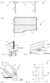
- the numeral 1 denotes in its entirety a liftable bed of a recreational vehicle made in accordance with the invention, hereinafter also referred to simply as the bed 1.
- the bed 1 comprises: two uprights 2, a base 3, a slat carrier device 4 and a plurality of slats 5.
- the two uprights 2 are integral with the recreational vehicle.
- the two uprights are installed inside the habitable space of the recreational vehicle.
- the base 3 slidably engages with the two uprights 2.
- the two uprights 2 each have a track, not illustrated, to allow the translation of the base 3.
- the base 3 is movable between at least a first lowered position BB, illustrated in Figures 1 and 2 , and at least one second raised position AA, illustrated in Figure 3 .
- at least a first lowered position BB is close to a first end 21 of one of the two uprights 2.
- at least a second raised position AA is close to a second end 22 of at least one of the two uprights 2, as shown in Figure 3 .
- the base 3 comprises a lower panel 31 of the bed 1 for isolating the bed from the surrounding environment or screening the plurality of slats 5.
- the base 3 comprises a frame 6 closed in a loop.
- the frame 6 defines the space necessary to receive a mattress, not illustrated, to be placed on the plurality of slats 5.
- the frame 6 comprises a first side wall 64 and a second side wall 65, wherein the second side wall 65 is opposite the first side wall 64, as illustrated in Figure 10 .
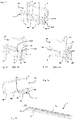
- the first side wall 64 has a guide 60 defined by a first protrusion 61 and a second protrusion 62, as illustrated in Figures 9 and 10 .
- the first protrusion 61 is located in a plane positioned above the second protrusion 62.
- the first protrusion 61 and the second 62 are separated and spaced from each other in such a way as to define the guide 60.
- the first protrusion 61 and the second 62 protrusion extend perpendicularly from the first side wall 64, as illustrated in Figures 9 and 10 .
- the second protrusion 62 is located along the lower half of the first side wall 64.
- the second protrusion 62 is positioned in such a way as to leave a free space beneath it, in such a way as to allow the passage, for example, of cables or other elements necessary for correct operation or comfort of the bed 1.
- the second protrusion 62 is positioned flush with the lower edge 64' of the first side wall 64.
- the first protrusion 61 has a coupling element 61' configured to engage on a coupling element 43 of the slat carrier device 4, described in more detail below. In this way, the slat carrier device 4 is constrained to the frame 6.
- the coupling element 61' is positioned on at least part of the outermost end edge 61" of the first protrusion 61.
- the slat carrier device 4 is configured to be constrained to the frame 6, for receiving the plurality of slats 5.
- the plurality of slats 5 is connected to the slat carrier device 4 in such a way that the slats 5 remain in position, to define the support surface of the mattress, not illustrated.
- the slat carrier device 4 in turn comprises a support base 41 and at least one blocking element 42.
- the support base 41 comprises an surface 411' of external extension configured to be positioned resting in the guide 60 of the frame 6.
- the surface 411' of external extension having a substantially triangular cross section.
- the surface 411' of external extension is defined in Figure 11 by the surfaces 411'a and 411'b.
- the support base 41 can come into contact with the second protrusion 62 of the frame 6.
- the support base 41 thanks to the surface 41'b, is also in contact with the first side wall 64, in such a way as to guarantee, in the manner of an end stop, the correct position of the slat carrier device 4 in the guide 60.
- the support base 41 does not engage on the first protrusion 61.
- the slat carrier device 4 comprises more than one blocking element 42.
- the blocking element 42 is configured to constrain a slat 5 on all four relative end sides, in such a way as to hold it in position even during the movements of the recreational vehicle.
- Each blocking element 42 is integral with the support base 41 and is configured to constrain one of the slats 5 in a predetermined position along the guide 60.
- the blocking element 42 is also configured to constrain the slat carrier device 4 to the guide 60.
- the blocking element 42 comprises an surface 412' of external extension having a substantially C-shaped cross section configured to be inserted at least partly into the guide 60 of the frame 6, as illustrated in Figure 12 .
- the surface 412' of external extension is defined by the surfaces with a, b, c, indicated in Figure 12 .
- the slat carrier device 4 comprises a coupling element 43.
- the coupling element 43 is located at the blocking element 42.
- the tooth 42' positioned on the upper surface of the blocking element 42 forms the coupling element 43 for the blocking element 42, as illustrated in Figure 12 .
- the tooth 42' which faces the first protrusion 61, is configured to engage with the coupling element 61' of the first protrusion 61, as illustrated in Figure 12 . In this way, the slat carrier device 4 is constrained to the frame 6.
- the slat carrier device 4 has a linear extension.
- the support base 41 is linear, as shown in the accompanying drawings.
- the blocking element 12 has a linear extension, as shown in the accompanying drawings.
- the slat carrier device 4 is made of flexible material so that it can be easily inserted in the guide 60 of the frame 6.
- the slat carrier device 4 is made in a single piece to give greater strength and stability to the slat carrier device 4.
- the bed 1 comprises a protection screen, to improve the safety of the bed 1 when used by children, for example, to prevent them from falling when the bed is suspended in the air.
- the slat carrier device 4 comprises coupling means 44 configured to be constrained with their first end edge 441 along the first protrusion 61 of the frame 6, at a portion of it not engaged by a blocking element 42, as illustrated in Figures 11, 12 and 13 .
- the coupling means 44 comprise a coupling tooth 441' configured for constraining the coupling means 44 to the coupling element 61' of the first protrusion 61, as illustrated in Figure 13 .
- the coupling means 44 also comprise a seat 442 for fixing the protective screen, not illustrated, to the frame 6.
- the coupling means 44 are removable, in such a way that they can be inserted when required.
- the coupling means 44 are made as one with the support base 41.
- the slat carrier device 4 also comprises further coupling means 45 for attaching an accessory element to the bed 1, as illustrated in Figure 11 .
- the bed 1 comprises a slat carrier insert 7, an example of which is shown in Figure 15 .
- the slat carrier insert 7 comprises a support base 71 having a surface 71' of external extension configured to be inserted into the guide 60 of the frame 6.
- the support base 71 has a substantially C-shaped cross section for constraining at least one of the slats 5 in a predetermined position along the guide 60 of the frame 6.
- the slat carrier insert 7 does not have elements for blocking the slat transversal to the main direction of extension DD of the insert itself.
- the slat 5 can be positioned in the most suitable position along the main direction of extension DD, depending on requirements.
- the support base 71 of the slat carrier insert 7 has at least one notch 72 to allow the insert 7 to follow a curved profile of the frame 6.
- the slats 5 in order to follow the curve, cannot be positioned equidistant from each other, but must follow one or more predetermined radiuses of curvature of the curve of the frame.
- the slat carrier insert 7 does not have blocks between one slat 5 and the adjacent slat.
- the slat carrier insert 7 is made of a flexible material so that it can be easily inserted into the guide 60 of the frame 6.
- the slat carrier insert 7 also comprises further coupling means 45, not illustrated, for attaching an accessory element to the bed 1.
- the further coupling means 45 are of the removable type, whilst according to other embodiments they are made in a single piece with the support base 71.
- the slat carrier device 4 is replaced by the slat carrier insert 7.
- the bed 1 comprises anti-tip means 8 configured to support the base 3, as illustrated in Figures 1 to 4 .
- Straps, ropes, belts or similar products represent the anti-tip means 8 for the bed 1.
- the anti-tip means 8 allow the bed 1 to be held down and prevent the bed from oscillating or rotating, which could adversely affect the safety and stability of the bed in different configurations of use.
- Configurations of use are, for example, the first position BB lowered towards a ground surface, to be able to access the bed, and the second position AA raised towards the ceiling of the habitable space, to facilitate the comfort of the recreational vehicle.
- the number of belts 8 is greater or smaller than two, based on the dimensions and weights of the bed 1.
- the bed 1 also comprises at least one device 10 for sliding anti-tip means 8 positioned on the second side wall 65 of the frame 6, as illustrated in Figure 14 .
- the frame 6 has a slot 63, as described in more detail below.
- the sliding device 10 comprises: an interlocking portion 11 and a stop portion 13.
- the interlocking portion 11 has an surface 11' of external extension, designed to define an opening 12.
- the portion 11 is configured to be inserted into the slot 63 of the frame 6.
- the device 10 is at least partly connected to the frame 6.
- the stop portion 13, which is integral with the interlocking portion 11, is configured in such a way that the device 10 has a substantially T-shaped profile. In effect, the stop portion 13 is configured to be positioned in contact with the second side wall 65 of the frame 6.
- the stop portion 13 is configured to be stably connected to the second side wall 65, for example with coupling means not illustrated.
- the anti-tip means 8 pass through the opening 12 to protrude from the side of the frame 6 defined by the second side wall 65.
- the device 10 is positioned flush with a lower edge 65' of the second wall 65 to prevent overhanging or surfaces projecting from the lower surface of the base 3 or of the frame 6.
- the anti-tip means 8 slide inside the sliding device 10, thanks to the opening 12, on opposite sides of the base 3.
- the bed 1 also comprises at least one guide 9 for supporting the anti-tip means 8, as illustrated in Figure 4 .
- the support guide 9 is positioned transversally to the bed 1 to intercept the anti-tip means 8.
- the support guide 9 is stably connected to the base 3. This increases the rigidity and the strength of the bed 1.
- the support guide 9 is also configured in such a way that the anti-tip means 8 emerge only at the ends of the base 3, at the frame 6 and the devices 10.
- the support guide 9 comprises a slot 91 in which the anti-tip means 8 slide, to facilitate the sliding and correct tensioning and position of the anti-tip means 8.
- the support guide 9 comprises at least one engagement seat 92 for connecting an accessory element to the bed 1.
- An accessory element is, for example, represented by an isolation panel, cupboards or objects such as to increase the comfort of the bed 1.
- the bed 1 comprises movement means 80 positioned close to one end of the base 3 for translating the base 3 along the two uprights 2 between at least a first position BB and at least a second position AA.
- the movement means 80 comprise a motor designed to move a shaft 81.
- the anti-tip means 8 are constrained with a relative first end to the shaft 81 and with the other end to the recreational vehicle, so that the anti-tip means 8 rotate on themselves during the translation of the base 3 along the two uprights 2.
- the bed 1 In use, when the movement means 8 are actuated, the bed 1, starting from a closed configuration, corresponding to the second raised position AA, shown in Figure 3 , moves to an open configuration shown, for example, by the first lowered position BB, illustrated in Figures 1 and 2 .
- the base 3 thus translates on the two uprights 2, whilst the anti-tip means 8 unwind about the shaft 81 to support the bed 1 whilst descending from the ceiling towards the habitable space of the recreational vehicle.
- the liftable bed of a recreational vehicle achieves the preset aims and brings important advantages.
- a first advantage of the bed according to the invention is the possibility of reducing the dimensions of the bed and thereby increasing the useful space of the recreational vehicle.
- the known profile P and the respective prior art slat carrier device DPD comprise a coupling which extends in an insertion plane of the slat carrier device DPD from the top downwards, as shown by the arrow FF in Figure 7 .
- the slats D are inserted in contrast between the slat carrier device DPD and the profile P, making installation difficult, as it is not possible to define in advance the position of the slats D.
- the shape of the prior art profile P comprising a seat SI for engaging the slat carrier device DPD facing upwards, determines the height H at which the slats D can be positioned.
- the guide 60 of the frame 6 allows the slat carrier device 4 to be inserted laterally, as indicated by the arrow FF' in Figure 9 .
- the height H' at which to position the slats 5 is considerably reduced with respect to the height H of the prior art devices, allowing the overall dimensions of the bed 1 to be reduced, especially in terms of height HL of the bed.
- Another advantage is due to the possibility of reducing the weights of a liftable bed of a recreational vehicle. Another advantage is the possibility of inserting the sliding device 10 flush with the bed, facilitating the installation, and allowing the projecting elements and the overhanging elements necessary for installing the lower panel 31 of the bed to be reduced.
- a further advantage is the possibility of facilitating the installation of the slats and also of being able to adapt them to different shapes of beds, for example if this has curvilinear stretches.
- Yet another advantage is the possibility of only having the coupling means 44 for the protection screen as required.
- the prior art solutions comprise means PV for coupling the protection screen positioned on the top of the profile P, thereby further increasing the overall dimensions of the profile P.
- the bed according to the invention comprises, on the other hand, the use of coupling means 44, to be inserted when required, and positioned at the first protrusion 61, thereby allowing a further reduction in the overall dimensions of the frame 6, and consequently of the bed 1.
- Yet another advantage is due to the fact that it is possible to fix accessory elements to the bed in different positions of the bed.
Landscapes
- Engineering & Computer Science (AREA)
- Health & Medical Sciences (AREA)
- Public Health (AREA)
- Transportation (AREA)
- Mechanical Engineering (AREA)
- General Health & Medical Sciences (AREA)
- Nursing (AREA)
- Seats For Vehicles (AREA)
- Vehicle Waterproofing, Decoration, And Sanitation Devices (AREA)
Priority Applications (1)
| Application Number | Priority Date | Filing Date | Title |
|---|---|---|---|
| SI202230029T SI4140809T1 (sl) | 2021-08-27 | 2022-08-22 | Dvižno ležišče v rekreacijskem vozilu |
Applications Claiming Priority (1)
| Application Number | Priority Date | Filing Date | Title |
|---|---|---|---|
| IT102021000022415A IT202100022415A1 (it) | 2021-08-27 | 2021-08-27 | Letto sollevabile di un veicolo ricreativo |
Publications (2)
| Publication Number | Publication Date |
|---|---|
| EP4140809A1 true EP4140809A1 (de) | 2023-03-01 |
| EP4140809B1 EP4140809B1 (de) | 2024-03-13 |
Family
ID=78649787
Family Applications (1)
| Application Number | Title | Priority Date | Filing Date |
|---|---|---|---|
| EP22191569.7A Active EP4140809B1 (de) | 2021-08-27 | 2022-08-22 | Hubbett eines freizeitfahrzeugs |
Country Status (4)
| Country | Link |
|---|---|
| US (1) | US20230065705A1 (de) |
| EP (1) | EP4140809B1 (de) |
| IT (1) | IT202100022415A1 (de) |
| SI (1) | SI4140809T1 (de) |
Families Citing this family (2)
| Publication number | Priority date | Publication date | Assignee | Title |
|---|---|---|---|---|
| USD1070446S1 (en) * | 2021-11-30 | 2025-04-15 | Kevin Dunn | Folding bed frame |
| EP4663477A1 (de) * | 2024-06-11 | 2025-12-17 | LCI Italy S.r.l. | Anhebbares bett eines freizeitfahrzeugs |
Citations (4)
| Publication number | Priority date | Publication date | Assignee | Title |
|---|---|---|---|---|
| GB1460567A (en) * | 1972-10-20 | 1977-01-06 | Slumberland Group Ltd | Beds |
| AT335657B (de) * | 1975-02-06 | 1977-03-25 | Wuester Mewaplast Ing H | Liegemobelgestell |
| US4592105A (en) * | 1984-02-14 | 1986-06-03 | Sico Incorporated | Bed frame construction |
| EP3093191A1 (de) * | 2015-05-13 | 2016-11-16 | Trigano VDL | Bettanordnung mit verstellbarer höhe, die einen längsverschiebbaren bettrahmen umfasst |
-
2021
- 2021-08-27 IT IT102021000022415A patent/IT202100022415A1/it unknown
-
2022
- 2022-08-22 SI SI202230029T patent/SI4140809T1/sl unknown
- 2022-08-22 EP EP22191569.7A patent/EP4140809B1/de active Active
- 2022-08-24 US US17/894,748 patent/US20230065705A1/en not_active Abandoned
Patent Citations (4)
| Publication number | Priority date | Publication date | Assignee | Title |
|---|---|---|---|---|
| GB1460567A (en) * | 1972-10-20 | 1977-01-06 | Slumberland Group Ltd | Beds |
| AT335657B (de) * | 1975-02-06 | 1977-03-25 | Wuester Mewaplast Ing H | Liegemobelgestell |
| US4592105A (en) * | 1984-02-14 | 1986-06-03 | Sico Incorporated | Bed frame construction |
| EP3093191A1 (de) * | 2015-05-13 | 2016-11-16 | Trigano VDL | Bettanordnung mit verstellbarer höhe, die einen längsverschiebbaren bettrahmen umfasst |
Also Published As
| Publication number | Publication date |
|---|---|
| IT202100022415A1 (it) | 2023-02-27 |
| US20230065705A1 (en) | 2023-03-02 |
| SI4140809T1 (sl) | 2024-05-31 |
| EP4140809B1 (de) | 2024-03-13 |
Similar Documents
| Publication | Publication Date | Title |
|---|---|---|
| EP4140809B1 (de) | Hubbett eines freizeitfahrzeugs | |
| US8776284B2 (en) | Moveable bed system | |
| US5535806A (en) | Roller blind, particularly for use as blackout shade | |
| US7584574B2 (en) | Sliding window assembly having a removable sliding panel | |
| RU2472911C2 (ru) | Устройство со шторой и элементом для повторной установки шторы в направляющую | |
| CN103101463B (zh) | 具有饮料保持器的扶手组件 | |
| GB2310173A (en) | A safety device for the interior of a vehicle. | |
| EP3330475A2 (de) | Schiene für eine architektonische öffnungsabdeckung | |
| US8584729B2 (en) | Mechanism for raising and lowering a dual shade covering a window | |
| ES2975334T3 (es) | Cama de techo modular para furgoneta reconvertida | |
| US5285993A (en) | Seat slide device with protecting cover | |
| KR20140122244A (ko) | 카브리오버스 | |
| EP1232888A1 (de) | Schutzelement für die Führungsschiene eines öffnungsfähigen Fahrzeugdaches | |
| US4941636A (en) | Locking slide apparatus for mounting a seat | |
| US6959961B2 (en) | Louver vehicle roof | |
| WO2013160183A1 (en) | Sunroof apparatus | |
| CA3040167A1 (en) | Side mounted sliding window | |
| JP2001055046A (ja) | 車輌用開口部の遮蔽装置 | |
| US8579003B2 (en) | Mechanism for raising and lowering a dual shade covering a window | |
| JP4226535B2 (ja) | ドアパネル構造およびウインドレギュレータ | |
| EP1710108A2 (de) | Vorhanganordnung für Fahrzeug mit Seitenplane | |
| KR100405810B1 (ko) | 승합차의 슬라이드형 사이드윈도우 | |
| EP0282583A1 (de) | Kraftfahrzeug-sonnendach | |
| KR200488580Y1 (ko) | 차량 도어용 차양 장치 | |
| KR101388282B1 (ko) | 선루프장치 |
Legal Events
| Date | Code | Title | Description |
|---|---|---|---|
| PUAI | Public reference made under article 153(3) epc to a published international application that has entered the european phase |
Free format text: ORIGINAL CODE: 0009012 |
|
| STAA | Information on the status of an ep patent application or granted ep patent |
Free format text: STATUS: THE APPLICATION HAS BEEN PUBLISHED |
|
| AK | Designated contracting states |
Kind code of ref document: A1 Designated state(s): AL AT BE BG CH CY CZ DE DK EE ES FI FR GB GR HR HU IE IS IT LI LT LU LV MC MK MT NL NO PL PT RO RS SE SI SK SM TR |
|
| STAA | Information on the status of an ep patent application or granted ep patent |
Free format text: STATUS: REQUEST FOR EXAMINATION WAS MADE |
|
| 17P | Request for examination filed |
Effective date: 20230418 |
|
| RBV | Designated contracting states (corrected) |
Designated state(s): AL AT BE BG CH CY CZ DE DK EE ES FI FR GB GR HR HU IE IS IT LI LT LU LV MC MK MT NL NO PL PT RO RS SE SI SK SM TR |
|
| P01 | Opt-out of the competence of the unified patent court (upc) registered |
Effective date: 20230522 |
|
| RIC1 | Information provided on ipc code assigned before grant |
Ipc: A47C 17/80 20060101ALI20230817BHEP Ipc: A47C 23/06 20060101ALI20230817BHEP Ipc: B60P 3/39 20060101AFI20230817BHEP |
|
| GRAP | Despatch of communication of intention to grant a patent |
Free format text: ORIGINAL CODE: EPIDOSNIGR1 |
|
| STAA | Information on the status of an ep patent application or granted ep patent |
Free format text: STATUS: GRANT OF PATENT IS INTENDED |
|
| INTG | Intention to grant announced |
Effective date: 20231016 |
|
| GRAS | Grant fee paid |
Free format text: ORIGINAL CODE: EPIDOSNIGR3 |
|
| GRAA | (expected) grant |
Free format text: ORIGINAL CODE: 0009210 |
|
| STAA | Information on the status of an ep patent application or granted ep patent |
Free format text: STATUS: THE PATENT HAS BEEN GRANTED |
|
| AK | Designated contracting states |
Kind code of ref document: B1 Designated state(s): AL AT BE BG CH CY CZ DE DK EE ES FI FR GB GR HR HU IE IS IT LI LT LU LV MC MK MT NL NO PL PT RO RS SE SI SK SM TR |
|
| REG | Reference to a national code |
Ref country code: GB Ref legal event code: FG4D |
|
| REG | Reference to a national code |
Ref country code: CH Ref legal event code: EP |
|
| REG | Reference to a national code |
Ref country code: DE Ref legal event code: R096 Ref document number: 602022002351 Country of ref document: DE |
|
| REG | Reference to a national code |
Ref country code: IE Ref legal event code: FG4D |
|
| PG25 | Lapsed in a contracting state [announced via postgrant information from national office to epo] |
Ref country code: LT Free format text: LAPSE BECAUSE OF FAILURE TO SUBMIT A TRANSLATION OF THE DESCRIPTION OR TO PAY THE FEE WITHIN THE PRESCRIBED TIME-LIMIT Effective date: 20240313 |
|
| REG | Reference to a national code |
Ref country code: LT Ref legal event code: MG9D |
|
| PG25 | Lapsed in a contracting state [announced via postgrant information from national office to epo] |
Ref country code: GR Free format text: LAPSE BECAUSE OF FAILURE TO SUBMIT A TRANSLATION OF THE DESCRIPTION OR TO PAY THE FEE WITHIN THE PRESCRIBED TIME-LIMIT Effective date: 20240614 |
|
| REG | Reference to a national code |
Ref country code: NL Ref legal event code: MP Effective date: 20240313 |
|
| PG25 | Lapsed in a contracting state [announced via postgrant information from national office to epo] |
Ref country code: HR Free format text: LAPSE BECAUSE OF FAILURE TO SUBMIT A TRANSLATION OF THE DESCRIPTION OR TO PAY THE FEE WITHIN THE PRESCRIBED TIME-LIMIT Effective date: 20240313 Ref country code: RS Free format text: LAPSE BECAUSE OF FAILURE TO SUBMIT A TRANSLATION OF THE DESCRIPTION OR TO PAY THE FEE WITHIN THE PRESCRIBED TIME-LIMIT Effective date: 20240613 |
|
| PG25 | Lapsed in a contracting state [announced via postgrant information from national office to epo] |
Ref country code: ES Free format text: LAPSE BECAUSE OF FAILURE TO SUBMIT A TRANSLATION OF THE DESCRIPTION OR TO PAY THE FEE WITHIN THE PRESCRIBED TIME-LIMIT Effective date: 20240313 |
|
| PG25 | Lapsed in a contracting state [announced via postgrant information from national office to epo] |
Ref country code: RS Free format text: LAPSE BECAUSE OF FAILURE TO SUBMIT A TRANSLATION OF THE DESCRIPTION OR TO PAY THE FEE WITHIN THE PRESCRIBED TIME-LIMIT Effective date: 20240613 Ref country code: NO Free format text: LAPSE BECAUSE OF FAILURE TO SUBMIT A TRANSLATION OF THE DESCRIPTION OR TO PAY THE FEE WITHIN THE PRESCRIBED TIME-LIMIT Effective date: 20240613 Ref country code: LT Free format text: LAPSE BECAUSE OF FAILURE TO SUBMIT A TRANSLATION OF THE DESCRIPTION OR TO PAY THE FEE WITHIN THE PRESCRIBED TIME-LIMIT Effective date: 20240313 Ref country code: HR Free format text: LAPSE BECAUSE OF FAILURE TO SUBMIT A TRANSLATION OF THE DESCRIPTION OR TO PAY THE FEE WITHIN THE PRESCRIBED TIME-LIMIT Effective date: 20240313 Ref country code: GR Free format text: LAPSE BECAUSE OF FAILURE TO SUBMIT A TRANSLATION OF THE DESCRIPTION OR TO PAY THE FEE WITHIN THE PRESCRIBED TIME-LIMIT Effective date: 20240614 Ref country code: FI Free format text: LAPSE BECAUSE OF FAILURE TO SUBMIT A TRANSLATION OF THE DESCRIPTION OR TO PAY THE FEE WITHIN THE PRESCRIBED TIME-LIMIT Effective date: 20240313 Ref country code: ES Free format text: LAPSE BECAUSE OF FAILURE TO SUBMIT A TRANSLATION OF THE DESCRIPTION OR TO PAY THE FEE WITHIN THE PRESCRIBED TIME-LIMIT Effective date: 20240313 Ref country code: BG Free format text: LAPSE BECAUSE OF FAILURE TO SUBMIT A TRANSLATION OF THE DESCRIPTION OR TO PAY THE FEE WITHIN THE PRESCRIBED TIME-LIMIT Effective date: 20240313 |
|
| REG | Reference to a national code |
Ref country code: AT Ref legal event code: MK05 Ref document number: 1665463 Country of ref document: AT Kind code of ref document: T Effective date: 20240313 |
|
| PG25 | Lapsed in a contracting state [announced via postgrant information from national office to epo] |
Ref country code: SE Free format text: LAPSE BECAUSE OF FAILURE TO SUBMIT A TRANSLATION OF THE DESCRIPTION OR TO PAY THE FEE WITHIN THE PRESCRIBED TIME-LIMIT Effective date: 20240313 Ref country code: LV Free format text: LAPSE BECAUSE OF FAILURE TO SUBMIT A TRANSLATION OF THE DESCRIPTION OR TO PAY THE FEE WITHIN THE PRESCRIBED TIME-LIMIT Effective date: 20240313 |
|
| PG25 | Lapsed in a contracting state [announced via postgrant information from national office to epo] |
Ref country code: NL Free format text: LAPSE BECAUSE OF FAILURE TO SUBMIT A TRANSLATION OF THE DESCRIPTION OR TO PAY THE FEE WITHIN THE PRESCRIBED TIME-LIMIT Effective date: 20240313 |
|
| PG25 | Lapsed in a contracting state [announced via postgrant information from national office to epo] |
Ref country code: NL Free format text: LAPSE BECAUSE OF FAILURE TO SUBMIT A TRANSLATION OF THE DESCRIPTION OR TO PAY THE FEE WITHIN THE PRESCRIBED TIME-LIMIT Effective date: 20240313 |
|
| PG25 | Lapsed in a contracting state [announced via postgrant information from national office to epo] |
Ref country code: IS Free format text: LAPSE BECAUSE OF FAILURE TO SUBMIT A TRANSLATION OF THE DESCRIPTION OR TO PAY THE FEE WITHIN THE PRESCRIBED TIME-LIMIT Effective date: 20240713 |
|
| PG25 | Lapsed in a contracting state [announced via postgrant information from national office to epo] |
Ref country code: SM Free format text: LAPSE BECAUSE OF FAILURE TO SUBMIT A TRANSLATION OF THE DESCRIPTION OR TO PAY THE FEE WITHIN THE PRESCRIBED TIME-LIMIT Effective date: 20240313 Ref country code: PT Free format text: LAPSE BECAUSE OF FAILURE TO SUBMIT A TRANSLATION OF THE DESCRIPTION OR TO PAY THE FEE WITHIN THE PRESCRIBED TIME-LIMIT Effective date: 20240715 |
|
| PG25 | Lapsed in a contracting state [announced via postgrant information from national office to epo] |
Ref country code: CZ Free format text: LAPSE BECAUSE OF FAILURE TO SUBMIT A TRANSLATION OF THE DESCRIPTION OR TO PAY THE FEE WITHIN THE PRESCRIBED TIME-LIMIT Effective date: 20240313 Ref country code: EE Free format text: LAPSE BECAUSE OF FAILURE TO SUBMIT A TRANSLATION OF THE DESCRIPTION OR TO PAY THE FEE WITHIN THE PRESCRIBED TIME-LIMIT Effective date: 20240313 |
|
| PG25 | Lapsed in a contracting state [announced via postgrant information from national office to epo] |
Ref country code: AT Free format text: LAPSE BECAUSE OF FAILURE TO SUBMIT A TRANSLATION OF THE DESCRIPTION OR TO PAY THE FEE WITHIN THE PRESCRIBED TIME-LIMIT Effective date: 20240313 |
|
| PG25 | Lapsed in a contracting state [announced via postgrant information from national office to epo] |
Ref country code: PL Free format text: LAPSE BECAUSE OF FAILURE TO SUBMIT A TRANSLATION OF THE DESCRIPTION OR TO PAY THE FEE WITHIN THE PRESCRIBED TIME-LIMIT Effective date: 20240313 |
|
| PG25 | Lapsed in a contracting state [announced via postgrant information from national office to epo] |
Ref country code: SK Free format text: LAPSE BECAUSE OF FAILURE TO SUBMIT A TRANSLATION OF THE DESCRIPTION OR TO PAY THE FEE WITHIN THE PRESCRIBED TIME-LIMIT Effective date: 20240313 |
|
| PG25 | Lapsed in a contracting state [announced via postgrant information from national office to epo] |
Ref country code: SM Free format text: LAPSE BECAUSE OF FAILURE TO SUBMIT A TRANSLATION OF THE DESCRIPTION OR TO PAY THE FEE WITHIN THE PRESCRIBED TIME-LIMIT Effective date: 20240313 Ref country code: SK Free format text: LAPSE BECAUSE OF FAILURE TO SUBMIT A TRANSLATION OF THE DESCRIPTION OR TO PAY THE FEE WITHIN THE PRESCRIBED TIME-LIMIT Effective date: 20240313 Ref country code: RO Free format text: LAPSE BECAUSE OF FAILURE TO SUBMIT A TRANSLATION OF THE DESCRIPTION OR TO PAY THE FEE WITHIN THE PRESCRIBED TIME-LIMIT Effective date: 20240313 Ref country code: PT Free format text: LAPSE BECAUSE OF FAILURE TO SUBMIT A TRANSLATION OF THE DESCRIPTION OR TO PAY THE FEE WITHIN THE PRESCRIBED TIME-LIMIT Effective date: 20240715 Ref country code: PL Free format text: LAPSE BECAUSE OF FAILURE TO SUBMIT A TRANSLATION OF THE DESCRIPTION OR TO PAY THE FEE WITHIN THE PRESCRIBED TIME-LIMIT Effective date: 20240313 Ref country code: IS Free format text: LAPSE BECAUSE OF FAILURE TO SUBMIT A TRANSLATION OF THE DESCRIPTION OR TO PAY THE FEE WITHIN THE PRESCRIBED TIME-LIMIT Effective date: 20240713 Ref country code: EE Free format text: LAPSE BECAUSE OF FAILURE TO SUBMIT A TRANSLATION OF THE DESCRIPTION OR TO PAY THE FEE WITHIN THE PRESCRIBED TIME-LIMIT Effective date: 20240313 Ref country code: CZ Free format text: LAPSE BECAUSE OF FAILURE TO SUBMIT A TRANSLATION OF THE DESCRIPTION OR TO PAY THE FEE WITHIN THE PRESCRIBED TIME-LIMIT Effective date: 20240313 Ref country code: AT Free format text: LAPSE BECAUSE OF FAILURE TO SUBMIT A TRANSLATION OF THE DESCRIPTION OR TO PAY THE FEE WITHIN THE PRESCRIBED TIME-LIMIT Effective date: 20240313 |
|
| REG | Reference to a national code |
Ref country code: DE Ref legal event code: R097 Ref document number: 602022002351 Country of ref document: DE |
|
| PG25 | Lapsed in a contracting state [announced via postgrant information from national office to epo] |
Ref country code: DK Free format text: LAPSE BECAUSE OF FAILURE TO SUBMIT A TRANSLATION OF THE DESCRIPTION OR TO PAY THE FEE WITHIN THE PRESCRIBED TIME-LIMIT Effective date: 20240313 |
|
| PLBE | No opposition filed within time limit |
Free format text: ORIGINAL CODE: 0009261 |
|
| STAA | Information on the status of an ep patent application or granted ep patent |
Free format text: STATUS: NO OPPOSITION FILED WITHIN TIME LIMIT |
|
| PG25 | Lapsed in a contracting state [announced via postgrant information from national office to epo] |
Ref country code: DK Free format text: LAPSE BECAUSE OF FAILURE TO SUBMIT A TRANSLATION OF THE DESCRIPTION OR TO PAY THE FEE WITHIN THE PRESCRIBED TIME-LIMIT Effective date: 20240313 |
|
| 26N | No opposition filed |
Effective date: 20241216 |
|
| PG25 | Lapsed in a contracting state [announced via postgrant information from national office to epo] |
Ref country code: LU Free format text: LAPSE BECAUSE OF NON-PAYMENT OF DUE FEES Effective date: 20240822 |
|
| PG25 | Lapsed in a contracting state [announced via postgrant information from national office to epo] |
Ref country code: MC Free format text: LAPSE BECAUSE OF FAILURE TO SUBMIT A TRANSLATION OF THE DESCRIPTION OR TO PAY THE FEE WITHIN THE PRESCRIBED TIME-LIMIT Effective date: 20240313 |
|
| REG | Reference to a national code |
Ref country code: BE Ref legal event code: MM Effective date: 20240831 |
|
| PG25 | Lapsed in a contracting state [announced via postgrant information from national office to epo] |
Ref country code: BE Free format text: LAPSE BECAUSE OF NON-PAYMENT OF DUE FEES Effective date: 20240831 |
|
| PG25 | Lapsed in a contracting state [announced via postgrant information from national office to epo] |
Ref country code: IE Free format text: LAPSE BECAUSE OF NON-PAYMENT OF DUE FEES Effective date: 20240822 |
|
| PGFP | Annual fee paid to national office [announced via postgrant information from national office to epo] |
Ref country code: DE Payment date: 20250819 Year of fee payment: 4 |
|
| PGFP | Annual fee paid to national office [announced via postgrant information from national office to epo] |
Ref country code: IT Payment date: 20250901 Year of fee payment: 4 |
|
| PGFP | Annual fee paid to national office [announced via postgrant information from national office to epo] |
Ref country code: FR Payment date: 20250821 Year of fee payment: 4 |
|
| PGFP | Annual fee paid to national office [announced via postgrant information from national office to epo] |
Ref country code: SI Payment date: 20250808 Year of fee payment: 4 |
|
| PG25 | Lapsed in a contracting state [announced via postgrant information from national office to epo] |
Ref country code: CY Free format text: LAPSE BECAUSE OF FAILURE TO SUBMIT A TRANSLATION OF THE DESCRIPTION OR TO PAY THE FEE WITHIN THE PRESCRIBED TIME-LIMIT; INVALID AB INITIO Effective date: 20220822 |
|
| PG25 | Lapsed in a contracting state [announced via postgrant information from national office to epo] |
Ref country code: HU Free format text: LAPSE BECAUSE OF FAILURE TO SUBMIT A TRANSLATION OF THE DESCRIPTION OR TO PAY THE FEE WITHIN THE PRESCRIBED TIME-LIMIT; INVALID AB INITIO Effective date: 20220822 |
|
| REG | Reference to a national code |
Ref country code: CH Ref legal event code: H13 Free format text: ST27 STATUS EVENT CODE: U-0-0-H10-H13 (AS PROVIDED BY THE NATIONAL OFFICE) Effective date: 20260324 |