EP4143405B1 - Vorhängeschloss - Google Patents
Vorhängeschloss Download PDFInfo
- Publication number
- EP4143405B1 EP4143405B1 EP21796755.3A EP21796755A EP4143405B1 EP 4143405 B1 EP4143405 B1 EP 4143405B1 EP 21796755 A EP21796755 A EP 21796755A EP 4143405 B1 EP4143405 B1 EP 4143405B1
- Authority
- EP
- European Patent Office
- Prior art keywords
- locking
- shackle
- lock core
- padlock
- ball
- Prior art date
- Legal status (The legal status is an assumption and is not a legal conclusion. Google has not performed a legal analysis and makes no representation as to the accuracy of the status listed.)
- Active
Links
Images




Classifications
-
- E—FIXED CONSTRUCTIONS
- E05—LOCKS; KEYS; WINDOW OR DOOR FITTINGS; SAFES
- E05B—LOCKS; ACCESSORIES THEREFOR; HANDCUFFS
- E05B67/00—Padlocks; Details thereof
-
- E—FIXED CONSTRUCTIONS
- E05—LOCKS; KEYS; WINDOW OR DOOR FITTINGS; SAFES
- E05B—LOCKS; ACCESSORIES THEREFOR; HANDCUFFS
- E05B15/00—Other details of locks; Parts for engagement by bolts of fastening devices
- E05B15/0053—Other details of locks; Parts for engagement by bolts of fastening devices means providing a stable, i.e. indexed, position of lock parts
- E05B15/006—Spring-biased ball or roller entering a notch
-
- E—FIXED CONSTRUCTIONS
- E05—LOCKS; KEYS; WINDOW OR DOOR FITTINGS; SAFES
- E05B—LOCKS; ACCESSORIES THEREFOR; HANDCUFFS
- E05B47/00—Operating or controlling locks or other fastening devices by electric or magnetic means
- E05B47/06—Controlling mechanically-operated bolts by electro-magnetically-operated detents
- E05B47/0611—Cylinder locks with electromagnetic control
-
- E—FIXED CONSTRUCTIONS
- E05—LOCKS; KEYS; WINDOW OR DOOR FITTINGS; SAFES
- E05B—LOCKS; ACCESSORIES THEREFOR; HANDCUFFS
- E05B63/00—Locks or fastenings with special structural characteristics
- E05B63/14—Arrangement of several locks or locks with several bolts, e.g. arranged one behind the other
- E05B63/143—Arrangement of several locks, e.g. in parallel or series, on one or more wings
-
- E—FIXED CONSTRUCTIONS
- E05—LOCKS; KEYS; WINDOW OR DOOR FITTINGS; SAFES
- E05B—LOCKS; ACCESSORIES THEREFOR; HANDCUFFS
- E05B67/00—Padlocks; Details thereof
- E05B67/06—Shackles; Arrangement of the shackle
- E05B67/063—Padlocks with removable shackles
-
- E—FIXED CONSTRUCTIONS
- E05—LOCKS; KEYS; WINDOW OR DOOR FITTINGS; SAFES
- E05B—LOCKS; ACCESSORIES THEREFOR; HANDCUFFS
- E05B67/00—Padlocks; Details thereof
- E05B67/06—Shackles; Arrangement of the shackle
- E05B67/22—Padlocks with sliding shackles, with or without rotary or pivotal movement
- E05B67/24—Padlocks with sliding shackles, with or without rotary or pivotal movement with built- in cylinder locks
-
- E—FIXED CONSTRUCTIONS
- E05—LOCKS; KEYS; WINDOW OR DOOR FITTINGS; SAFES
- E05B—LOCKS; ACCESSORIES THEREFOR; HANDCUFFS
- E05B47/00—Operating or controlling locks or other fastening devices by electric or magnetic means
- E05B47/0001—Operating or controlling locks or other fastening devices by electric or magnetic means with electric actuators; Constructional features thereof
- E05B2047/0014—Constructional features of actuators or power transmissions therefor
- E05B2047/0018—Details of actuator transmissions
- E05B2047/0024—Cams
-
- E—FIXED CONSTRUCTIONS
- E05—LOCKS; KEYS; WINDOW OR DOOR FITTINGS; SAFES
- E05B—LOCKS; ACCESSORIES THEREFOR; HANDCUFFS
- E05B47/00—Operating or controlling locks or other fastening devices by electric or magnetic means
- E05B2047/0084—Key or electric means; Emergency release
-
- E—FIXED CONSTRUCTIONS
- E05—LOCKS; KEYS; WINDOW OR DOOR FITTINGS; SAFES
- E05B—LOCKS; ACCESSORIES THEREFOR; HANDCUFFS
- E05B35/00—Locks for use with special keys or a plurality of keys ; keys therefor
-
- Y—GENERAL TAGGING OF NEW TECHNOLOGICAL DEVELOPMENTS; GENERAL TAGGING OF CROSS-SECTIONAL TECHNOLOGIES SPANNING OVER SEVERAL SECTIONS OF THE IPC; TECHNICAL SUBJECTS COVERED BY FORMER USPC CROSS-REFERENCE ART COLLECTIONS [XRACs] AND DIGESTS
- Y10—TECHNICAL SUBJECTS COVERED BY FORMER USPC
- Y10T—TECHNICAL SUBJECTS COVERED BY FORMER US CLASSIFICATION
- Y10T70/00—Locks
- Y10T70/40—Portable
- Y10T70/413—Padlocks
Definitions
- the present invention relates to a padlock comprising a lock body, a shackle having two shackle legs, a locking mechanism for locking the shackle to the lock body, a selectively rotatable lock core, wherein said lock core is arranged to operate said locking mechanism for locking and unlocking the padlock.
- the present invention also relates to a replaecable padlock shackle.
- US 8,904,833 shows a padlock which includes a lock body, a shackle having two legs and a locking mechanism for locking the shackle to the lock body.
- the locking mechanism comprises a rotatable cam and two locking balls.
- the padlock is in locked status, the locking balls are engaged with notches of the first and second shackle legs.
- the cam is rotated to a position where the two locking balls are located corresponding to recesses formed in the cam, so that the locking balls are able to be located in the recesses, and the shackle can be pulled upward until the first shackle leg is completely removed from the lock body.
- the shackle is replaceable by use of a tool.
- this padlock may be considered bulky. Also, replacement of the shackle may be considered cumbersome.
- An object of the present invention is to provide a compact padlock.
- Another object of the present invention is to provide a compact padlock that can be operated independently by two different keys.
- a padlock comprising a lock body, a shackle having two shackle legs, a locking mechanism for locking the shackle to the lock body, a selectively rotatable lock core, wherein said lock core is arranged to operate said locking mechanism for locking and unlocking the padlock, wherein said locking mechanism, contrary to the state of the art, comprises at least three locking elements in the form of at least three locking balls which, when the locking mechanism is in a locked state, are disposed side by side in a first direction extending between a first locking element recess formed in the first shackle leg and a second locking element recess formed in the second shackle leg.
- Said padlock further comprises a rotatable member being attached to said lock core and comprising a retaining portion, which is configured to retain a first locking ball of the locking mechanism in a locking position when said lock core is situated in a first lock core position, and a release cavity which is configured to, upon rotation of said lock core from its lock core position to a second lock core position, receive said first locking element, wherein said release cavity is configured to allow movement of the first locking ball in a second direction, which is different from said first direction, from its locking position to a non-locking position in which the shackle is disengaged from the lock body, thereby allowing withdrawal of the shackle.
- a compact padlock is provided, since the locking element is arranged to be moved in a second direction upon unlocking.
- the retaining portion of the rotatable member only need to, in a locked state, support the first locking ball to prevent it from moving in the second direction and do not need to block the locking balls from lateral displacement, which enables a compact solution.
- a compact solution as seen in the first direction is provided.
- the first locking ball In the locked state the first locking ball thus itself holds the other locking balls in place and prevents them from leaving their respective locking recesses.
- a padlock with a high level of security is enabled, since unlocking movement of each of said locking balls is mechanically blocked by the retaining portion of the rotatable member.
- said second direction is orthogonal to said first direction.
- first direction corresponds to a horizontal direction and the second direction corresponds to a vertical direction.
- Each of said locking elements is thus a ball.
- said lock core form part of an electromechanical lock.
- an electromechanical lock may be configured to be operated by a programmable key, in the form of a physical programmable key configured to be inserted into a key receptacle of the electromechanical lock cylinder, or in the form of a mobile device, such as a mobile phone, which mobile device is configured to communicate with a lock core rotation device of the electromechanical lock.
- said rotatable member comprises a guiding surface which is configured to, upon rotation of said lock core, move the first locking ball from its non-locking position to its locking position.
- At least one release member forms a positioning element configured to, when the first locking ball is situated in its locking position, hold the first locking element in an offset position relative to the other locking elements.
- the release member is a non-movable member which holds the first locking element pre-positioned in such a position that movement thereof is initiated upon rotation of the first lock core.
- the non-movable member thus forms a static member of the padlock.
- the non-movable release member may be formed integral with or secured to the lock body.
- the retaining portion of the rotatable member may then, if the retaining portion is flat, be arranged such that the first locking ball is situated vertically below the other locking balls, i.e. in an offset position, as seen when the padlock is situated in an upright position, i.e. in a position in which the visible portion of shackle is located vertically above the lock body.
- the retaining portion may be formed with a recess, the depth of which is adapted to hold the first locking ball in such an offset position.
- said locking mechanism comprises at least five locking balls which, when the locking mechanism is in a locked state, are disposed side by side in said first direction, and said padlock further comprising a second selectively rotatable lock core, arranged to independently operate said locking mechanism for locking and unlocking the padlock, and a second rotatable member being attached to said second lock core and comprising a retaining portion, which is configured to retain a second locking ball of the locking mechanism in a locking position when the second lock core is in a first lock core position, and a release cavity which is configured to, upon rotation of the second lock core from the first lock core position to a second lock core position, receive said second locking ball, wherein said second rotatable member is configured to allow movement of said second locking ball in the second direction from its locking position to a non-locking position in which the shackle is disengaged from the lock body, thereby allowing withdrawal of the shackle.
- a first opening device such as a programmable key in the form of a physical key or in the form of a mobile device, may operate the first locking device and a second opening device, such as a mechanical key, may operate the second locking device.
- the padlock may thus be unlocked by a key inserted in the key receptacle of a first lock or by a key inserted in the key receptacle of a second lock.
- a padlock that is possible to independently operate with two different keys is thus achieved.
- each rotatable member provides for a robust and reliable operation of the locking mechanism.
- At least one of said release members comprises a magnetic element.
- a first rotatable member 29 is attached to the first lock core 25.
- the first rotatable member 29 comprises a first retaining portion 31 and a first release cavity 33, as illustrated in Fig. 1A .
- the first rotatable member 29 further comprises a first guiding surface 34 which is disposed in connection to the first release cavity 33.
- the first rotatable member 29 is attached to the first lock core 25 so as to rotate therewith upon rotation thereof.
- the guiding surface 34 raises from the bottom surface of the first release cavity 33 to the first retaining portion 31. In other words the first guiding surface 34 connects the the bottom surface of the first release cavity 33 and retaining surface of the first retaining portion 31.
- the mechanical lock cylinder 21 comprises a lock cylinder body 35 and a second lock core 37 located within the lock cylinder body 35.
- the second lock core 37 is provided with a key receptacle 38 for receiving a key and is selectively rotatable with respect to the lock cylinder body 35.
- a locking ball cavity 61 is formed in the second lock body part 3b.
- the locking ball cavity 61 is configured to receive the locking balls 51, 53, 55, 57, 59 of the locking mechanism 10.
- the circumferential groove 75 is configured to receive the spring-biased ball 65 of the shackle retaining device 63 to allow rotation of the shackle 5 relative the lock body 3.
- the first flat portion 66 which provides a bearing surface to the spring-biased ball 65 upon withdrawal of the shackle 5, extends from the first locking ball recess 45 to the circumferential groove 75.
- the depth to which the first flat portion 66 is recessed in to the first shackle leg 7 is approximately the same as the depth of the circumferential groove 75.
- the second release arrangement 81 comprises a release member, in the form of a spring-biased ball 89, as illustrated in the enlarged part of Fig. 3A .
- the spring-biased ball 89 is arranged to apply a force on the second locking ball 53 and thereby press the third locking ball 53 against the retaining portion 41 of the second rotatable member 39.
- the programmable key 91 which is used to operate the electromechanical lock 19, comprises an energy source, such as a battery, and a control unit powered by the energy source.
- the key 91 can access a cloud based or locally hosted access control system which transfer authorization data to the key or log information from the key 91 to the access control system via internet and a synchronization unit or via a mobile communication system such as the GSM net and a mobile device, such as a mobile phone.
- the mobile device is the key itself.
- the key 91 access the synchronization unit or the mobile device by a physical contact, by near field communication, such as NFC, or by radio communication, such as Bluetooth.
- the key 91 can store all data necessary to access at least one specific electromechanical lock 19, but cannot access any electromechanical locks for which it does not have the appropriate authorization data. Locking and unlocking of a lock using the programmable key 91 is rendered possible only if the programmable key is synchronized appropriately via the synchronization unit or a mobile device. Further, the programmable key 91 is provided with means by which electrical power, data and mechanical effort can be transmitted to the lock in a known manner.
- the electromechanical lock 19 is configured to be powered by and communicate with the programmable key 91 upon the insertion of the key 91 in the key receptacle 27. To this end the electromechanical lock 19 comprises power receiving means, communication means, access control device for controlling access of a key 91 inserted in the key receptacle 27 and an electrical control unit.
- Fig. 2A illustrates the padlock 1 in a locked state.
- the third locking ball 55 engages the wall of the first locking ball recess 45 and the fourth locking ball 57 engages the wall of the second locking ball recess 47.
- the first locking ball 51 is situated in a locking position, in which it is supported by the first retaining portion 31, and the second locking ball 53 is situated in a locking position, in which it is supported by the second retaining portion 41.
- the fifth locking ball 59 which is disposed between the first locking ball 51 and the second locking ball 53, prevents the other locking balls 55, 57, 59 from being displaced laterally.
- the intermediate locking balls 51, 53, 59 together prevent the third and fourth locking balls 55, 57 from being displaced from their respective locking ball recesses 45, 47.
- the locking balls are disposed side by side in the first direction.
- the third locking ball 55 and the fourth locking ball 57 are then free to move out of the first locking element recess 45 and the second locking element recess 47, respectively, as illustrated by arrows E and F in Fig. 2C , which allows the shackle 5 from to be withdrawn, as illustrated by arrows G in Fig. 2C , to place the padlock 1 in an unlocked state.
- the shackle 5 is withdrawn until the spring-biased ball 65 is received in the circumferential groove 75, as best illustrated in Fig. 2D .
- the second shackle leg 9 is completely withdrawn from the lock body 3 while the first shackle leg 7 is still within the shackle leg bore 11 and connected to the lock body 3 by the shackle retaining device 63.
- the first lock core 25 is thus rotated to permit movement of the locking balls 51, 53, 55, 57, 59 for disengaging the shackle 5, thereby permitting movement of the shackle 5 in a direction away from the lock body 3 and removal of the shorter leg 5 from the corresponding shackle leg bore 13 for placing the padlock 1 in an unlocked state.
- the locking mechanism 10 thus comprises locking elements, in the form of locking balls 51, 53, 55, 57, 59, each of which is movable between a locking position, in which it, together with the other locking elements, prevents the shackle 5 from being withdrawn from the lock body 3, and a releasing position in which it permis the shackle 5 from being withdrawn from the lock body 3.
- the third locking ball 55 is moved into the first locking ball recess 45
- the fourth locking ball 57 is moved into the second locking ball recess 47
- the intermediate locking balls 51, 53, 59 are moved into positions in which they together prevent the third 55 and fourth 57 locking balls from being displaced from their respective locking ball recesses 45, 47.
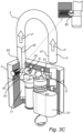
- FIG. 3A illustrates the padlock 1 in the locked state, which has been described hereinbefore with reference to Fig. 2A .
- the first release cavity 43 is exposed to the second locking ball 53.
- the second locking ball 53 is free to move in a second direction, which is orthogonal to the first direction, from its locking position into the second release cavity 43, as schematically illustrated by arrow K in Fig. 3B .
- the second locking ball 53 is forced to move away from its locking position by the releasing member 89, as illustrated by arrows L and M in the enlarged part of Fig. 3B .
- the movement of the second locking ball 53 away from its locking position is thus initiated by the spring-biased ball 89 which exerts a force on the second locking ball 53.
- the release cavities 33, 43 thus enables the third locking ball 55 and the fourth locking ball 57 to be moved from the first locking ball recess 45 and the second locking ball recess 47, respectively and thereby the locking mechanism to be moved to an unlocking position in which it permits withdrawal of the shackle 5 from the lock body 3.
- the longer shackle leg 95 of a replacement shackle 97 e.g. a shackle with more clearance between the shackle 97 and the lock body 3 can be inserted into the first shackle leg bore 11, as illustrated by arrows T in Fig. 4C , and used together with the lock body 3 in the manner previously described for the replaced shackle 5.
- a replacement shackle 97 e.g. a shackle with more clearance between the shackle 97 and the lock body 3
- the replacement shackle 97 it is oriented such that the second flat surface 99 of the longer shackle leg 95 faces the spring-biased ball 65 of the shackle retaining device 63.
- the second embodiment differs from the first embodiment in that the padlock 201 comprises one single lock core 25 instead of two lock cores.
- the locking balls are disposed side by side in a first direction extending between the first locking element recess 45 and the second locking element recess 47 in such a manner that the first locking ball 51 is in contact with each of the second locking ball 55 and the third locking ball 57.
- a second locking ball 55 is arranged to be received in the first locking element recess 45 and engage the wall thereof and a third locking ball 57 is arranged to be received in the second locking ball recess 47 and engage the wall thereof.
- the first locking ball 51 i.e. the intermediate locking ball, is configured to maintain the second locking ball 55 in the first locking ball recess 45 and the third locking ball 57 in the second locking ball recess 47 when the padlock 1 is in its locked state.
- the padlock may be provided with a movable release member.
- a release member may instead comprise a non-movable member configured to hold a locking ball in an offset position and, upon rotation of a lock core, act to initiate movement of the locking element into the release cavity of the corresponding rotatable member.
Landscapes
- Engineering & Computer Science (AREA)
- Structural Engineering (AREA)
- Physics & Mathematics (AREA)
- Electromagnetism (AREA)
- Refuge Islands, Traffic Blockers, Or Guard Fence (AREA)
Claims (10)
- Vorhängeschloss (1; 201), umfassendeinen Schlosskörper (3; 203),einen Bügel (5) mit zwei Bügelschenkeln (7, 9),einen Verriegelungsmechanismus (10) zum Verriegeln des Bügels (5) mit dem Schlosskörper (3; 203),einen selektiv drehbaren Schlosskern (25),wobei der Schlosskern (25) dazu dient, den Verriegelungsmechanismus (10) zum Verriegeln und Entriegeln des Vorhängeschlosses (1) zu betätigen,wobei der Verriegelungsmechanismus mindestens drei Verriegelungskugeln (51, 53, 59) umfasst, die, wenn sich der Verriegelungsmechanismus in einem verriegelten Zustand befindet, nebeneinander in einer ersten Richtung angeordnet sind, die sich zwischen einer ersten Verriegelungselementaussparung (45), die im ersten Bügelschenkel (7) ausgebildet ist, und einer zweiten Verriegelungselementaussparung (47), die im zweiten Bügelschenkel (9) ausgebildet ist, erstreckt,wobei das Vorhängeschloss ferner ein drehbares Element (29) umfasst, das an dem Schlosskern (25) befestigt ist und einen Halteabschnitt (31) umfasst, der konfiguriert ist, um eine erste Verriegelungskugel (51) des Verriegelungsmechanismus (10) in einer Verriegelungsposition zu halten, wenn sich der Schlosskern (25) in einer ersten Schlosskernposition befindet, und einen Freigabehohlraum (33), der konfiguriert ist, um bei einer Drehung des Schlosskerns (25) aus seiner ersten Schlosskernposition in eine zweite Schlosskernposition die erste Verriegelungskugel (51) aufzunehmen,wobei der Freigabehohlraum (33) konfiguriert ist, um eine Bewegung der ersten Verriegelungskugel (51) in einer zweiten Richtung, die sich von der ersten Richtung unterscheidet, aus ihrer Verriegelungsposition in eine Nichtverriegelungsposition zu ermöglichen, in der der Bügel (5) vom Schlosskörper (3; 203) gelöst ist, wodurch ein Herausziehen des Bügels (5) ermöglicht wird.
- Vorhängeschloss (1; 201) nach Anspruch 1, wobei der Freigabehohlraum (33) konfiguriert ist, um bei Drehung des Schlosskerns (25) aus seiner ersten Schlosskernposition in seine zweite Schlosskernposition die erste Verriegelungskugel (51) vollständig aufzunehmen.
- Vorhängeschloss (1; 201) nach einem der vorhergehenden Ansprüche, wobei die zweite Richtung orthogonal zur ersten Richtung ist.
- Vorhängeschloss (1; 201) nach einem der vorhergehenden Ansprüche, wobei der Schlosskern (25) Teil eines elektromechanischen Schlosses (19) ist.
- Vorhängeschloss nach einem der vorhergehenden Ansprüche, wobei das drehbare Element (29) eine Führungsoberfläche (34) aufweist, die konfiguriert ist, um bei Drehung des Schlosskerns (25) die erste Verriegelungskugel (51) aus ihrer nicht verriegelnden Position in ihre verriegelnde Position zu bewegen.
- Vorhängeschloss (1; 201) nach einem der vorhergehenden Ansprüche, wobei das Vorhängeschloss ferner ein Freigabeelement (79) umfasst, das angeordnet ist, um eine Kraft auf die erste Verriegelungskugel (51) auszuüben, wobei die Kraft bei Drehung des drehbaren Elements (29) wirkt, um eine Bewegung der ersten Verriegelungskugel (51) in den Freigabehohlraum (33) einzuleiten.
- Vorhängeschloss (1; 201) nach Anspruch 6, wobei das Freigabeelement (79) ein federvorgespanntes Element und vorzugsweise eine federvorgespannte Kugel (87) umfasst.
- Vorhängeschloss nach Anspruch 6, wobei mindestens ein Freigabeelement ein Positionierungselement bildet, das konfiguriert ist, um die erste Verriegelungskugel in einer versetzten Position relativ zu den anderen Verriegelungskugeln zu halten, wenn sich die erste Verriegelungskugel in ihrer Verriegelungsposition befindet.
- Vorhängeschloss (1) nach einem der vorhergehenden Ansprüche, wobei der Verriegelungsmechanismus (10) mindestens fünf Verriegelungskugeln (51, 53, 55, 57, 59) umfasst, die, wenn sich der Verriegelungsmechanismus in einem verriegelten Zustand befindet, in der ersten Richtung nebeneinander angeordnet sind, und wobei das Vorhängeschloss ferner einen zweiten selektiv drehbaren Schlosskern (37) umfasst, der angeordnet ist, um den Verriegelungsmechanismus (10) zum Verriegeln und Entriegeln des Vorhängeschlosses (1) unabhängig zu betätigen, undein zweites drehbares Element (39), das an dem zweiten Schlosskern (37) befestigt ist und einen Halteabschnitt (41), der konfiguriert ist, um eine zweite Verriegelungskugel (53) des Verriegelungsmechanismus (10) in einer Verriegelungsposition zu halten, wenn sich der zweite Schlosskern (37) in einer ersten Schlosskernposition befindet, und einen Freigabehohlraum (43) umfasst, der konfiguriert ist, um bei einer Drehung des zweiten Schlosskerns (37) aus seiner ersten Schlosskernposition in eine zweite Schlosskernposition die zweite Verriegelungskugel (53) aufzunehmen,wobei das zweite drehbare Element (39) konfiguriert ist, um eine Bewegung der zweiten Verriegelungskugel (53) in einer zweiten Richtung, die sich von der ersten Richtung unterscheidet, aus ihrer Verriegelungsposition in eine Nichtverriegelungsposition zu ermöglichen, in der der Bügel (5) vom Schlosskörper (3) gelöst ist, wodurch ein Herausziehen des Bügels (5) ermöglicht wird.
- Vorhängeschloss (1; 201) nach einem der vorhergehenden Ansprüche,
wobei der erste Bügelschenkel (7) mit einer Umfangsnut (75), einem ersten vertieften Abschnitt (66) zwischen der ersten Verriegelungselementaussparung (45) und der Umfangsnut (75) und einem zweiten vertieften Abschnitt (77) versehen ist, der sich von der Umfangsnut (75) erstreckt und am äußersten Abschnitt des freien Endes (7a) des ersten Bügelschenkels (7) endet, wobei der zweite vertiefte Abschnitt (77) konfiguriert ist, um ein vollständiges Herausziehen des ersten Bügelschenkels (7) aus dem Schlosskörper (3; 203) zu ermöglichen.
Applications Claiming Priority (2)
| Application Number | Priority Date | Filing Date | Title |
|---|---|---|---|
| SE2050477A SE2050477A1 (en) | 2020-04-27 | 2020-04-27 | Padlock |
| PCT/SE2021/050380 WO2021221549A1 (en) | 2020-04-27 | 2021-04-26 | Padlock |
Publications (4)
| Publication Number | Publication Date |
|---|---|
| EP4143405A1 EP4143405A1 (de) | 2023-03-08 |
| EP4143405A4 EP4143405A4 (de) | 2024-05-29 |
| EP4143405B1 true EP4143405B1 (de) | 2025-06-25 |
| EP4143405C0 EP4143405C0 (de) | 2025-06-25 |
Family
ID=78083406
Family Applications (1)
| Application Number | Title | Priority Date | Filing Date |
|---|---|---|---|
| EP21796755.3A Active EP4143405B1 (de) | 2020-04-27 | 2021-04-26 | Vorhängeschloss |
Country Status (3)
| Country | Link |
|---|---|
| EP (1) | EP4143405B1 (de) |
| SE (1) | SE2050477A1 (de) |
| WO (1) | WO2021221549A1 (de) |
Families Citing this family (3)
| Publication number | Priority date | Publication date | Assignee | Title |
|---|---|---|---|---|
| US11568693B2 (en) * | 2020-07-24 | 2023-01-31 | Konnex Enterprises Inc. | Systems, devices, and methods for controlling access to a secure space |
| CN116591554B (zh) * | 2023-05-15 | 2025-08-29 | 国网陕西省电力有限公司西安供电公司 | 一种nb-iot智能挂锁 |
| EP4729724A1 (de) * | 2024-10-18 | 2026-04-22 | Swedlock AB | Vorhängeschloss |
Family Cites Families (10)
| Publication number | Priority date | Publication date | Assignee | Title |
|---|---|---|---|---|
| US912773A (en) * | 1908-08-12 | 1909-02-16 | Yale & Towne Mfg Co | Duplex or master-key lock. |
| US2460615A (en) * | 1945-06-07 | 1949-02-01 | Yale & Towne Mfg Co | Removable core lock |
| US4158952A (en) * | 1978-07-14 | 1979-06-26 | Medeco Security Locks, Inc. | Padlock with removable top closure |
| US20030196461A1 (en) * | 2002-04-17 | 2003-10-23 | Gaieter Liou | Padlock |
| CN1957154A (zh) * | 2004-03-12 | 2007-05-02 | 总锁有限责任公司 | 遥控安全装置 |
| CN101029548B (zh) * | 2006-03-02 | 2011-02-09 | 川斯海洋集团有限公司 | 可快速更换锁钩的挂锁 |
| CA2804820C (en) * | 2010-07-15 | 2015-05-19 | Master Lock Company Llc | Padlock |
| US8904833B1 (en) | 2013-07-22 | 2014-12-09 | Federal Lock Co., Ltd. | Lock with replaceable shackle |
| JP2015067970A (ja) * | 2013-09-26 | 2015-04-13 | セイコークロック株式会社 | 電子錠 |
| CN105178740A (zh) * | 2015-10-15 | 2015-12-23 | 温州市法兰特锁业有限公司 | 一种挂锁 |
-
2020
- 2020-04-27 SE SE2050477A patent/SE2050477A1/en unknown
-
2021
- 2021-04-26 WO PCT/SE2021/050380 patent/WO2021221549A1/en not_active Ceased
- 2021-04-26 EP EP21796755.3A patent/EP4143405B1/de active Active
Also Published As
| Publication number | Publication date |
|---|---|
| EP4143405A4 (de) | 2024-05-29 |
| SE543997C2 (en) | 2021-10-26 |
| EP4143405A1 (de) | 2023-03-08 |
| WO2021221549A1 (en) | 2021-11-04 |
| EP4143405C0 (de) | 2025-06-25 |
| SE2050477A1 (en) | 2021-10-26 |
Similar Documents
| Publication | Publication Date | Title |
|---|---|---|
| EP4143405B1 (de) | Vorhängeschloss | |
| US7845202B2 (en) | Interchangeable electromechanical lock core | |
| CN103953229B (zh) | 一种机械复合锁 | |
| CN110118036B (zh) | 双重解锁模式挂锁 | |
| US9587415B2 (en) | Sidebit operated interchangeable core control lug | |
| US10041275B2 (en) | Combination lock structure for simple password retrieval | |
| US20140130555A1 (en) | Data port lock | |
| JP2012502205A (ja) | 移動可能な鍵組み合わせ部材を持つ鍵装置および錠アセンブリー | |
| US10047540B2 (en) | Locking device | |
| US12247416B2 (en) | Electromechanical lock assembly | |
| JP6449481B2 (ja) | 錠前装置および施錠装置 | |
| CN106437325A (zh) | 电子锁 | |
| US20070214850A1 (en) | Lock assembly | |
| US12601204B2 (en) | Smart lock | |
| US20190277063A1 (en) | Security lock | |
| RU2443841C2 (ru) | Магнитный блок как средство блокировки магнитного кодового замка | |
| CN103608537B (zh) | 磁性排斥锁组件 | |
| EP4038251B1 (de) | Elektromechanische schliessvorrichtung mit ringförmigem element, sperr- und halteeinrichtungen | |
| JP2019206864A (ja) | 錠装置 | |
| AU2019210588B9 (en) | Secure product | |
| CN205822953U (zh) | 行李箱密码锁 | |
| CN105386649A (zh) | 圆筒锁 | |
| EP3070235A1 (de) | Schlüsselaufbewahrungsvorrichtung | |
| JPS63501162A (ja) | 安全装置及び方法 | |
| AU2013204530B1 (en) | Lock Structure |
Legal Events
| Date | Code | Title | Description |
|---|---|---|---|
| STAA | Information on the status of an ep patent application or granted ep patent |
Free format text: STATUS: THE INTERNATIONAL PUBLICATION HAS BEEN MADE |
|
| PUAI | Public reference made under article 153(3) epc to a published international application that has entered the european phase |
Free format text: ORIGINAL CODE: 0009012 |
|
| STAA | Information on the status of an ep patent application or granted ep patent |
Free format text: STATUS: REQUEST FOR EXAMINATION WAS MADE |
|
| 17P | Request for examination filed |
Effective date: 20221115 |
|
| AK | Designated contracting states |
Kind code of ref document: A1 Designated state(s): AL AT BE BG CH CY CZ DE DK EE ES FI FR GB GR HR HU IE IS IT LI LT LU LV MC MK MT NL NO PL PT RO RS SE SI SK SM TR |
|
| DAV | Request for validation of the european patent (deleted) | ||
| DAX | Request for extension of the european patent (deleted) | ||
| REG | Reference to a national code |
Ref country code: DE Ref legal event code: R079 Free format text: PREVIOUS MAIN CLASS: E05B0067000000 Ipc: E05B0067240000 Ref document number: 602021032976 Country of ref document: DE |
|
| A4 | Supplementary search report drawn up and despatched |
Effective date: 20240425 |
|
| RIC1 | Information provided on ipc code assigned before grant |
Ipc: E05B 47/00 20060101ALI20240419BHEP Ipc: E05B 67/06 20060101ALI20240419BHEP Ipc: E05B 67/24 20060101AFI20240419BHEP |
|
| GRAP | Despatch of communication of intention to grant a patent |
Free format text: ORIGINAL CODE: EPIDOSNIGR1 |
|
| STAA | Information on the status of an ep patent application or granted ep patent |
Free format text: STATUS: GRANT OF PATENT IS INTENDED |
|
| INTG | Intention to grant announced |
Effective date: 20250130 |
|
| GRAS | Grant fee paid |
Free format text: ORIGINAL CODE: EPIDOSNIGR3 |
|
| GRAA | (expected) grant |
Free format text: ORIGINAL CODE: 0009210 |
|
| STAA | Information on the status of an ep patent application or granted ep patent |
Free format text: STATUS: THE PATENT HAS BEEN GRANTED |
|
| AK | Designated contracting states |
Kind code of ref document: B1 Designated state(s): AL AT BE BG CH CY CZ DE DK EE ES FI FR GB GR HR HU IE IS IT LI LT LU LV MC MK MT NL NO PL PT RO RS SE SI SK SM TR |
|
| REG | Reference to a national code |
Ref country code: GB Ref legal event code: FG4D |
|
| REG | Reference to a national code |
Ref country code: CH Ref legal event code: EP |
|
| REG | Reference to a national code |
Ref country code: CH Ref legal event code: EP |
|
| REG | Reference to a national code |
Ref country code: IE Ref legal event code: FG4D |
|
| REG | Reference to a national code |
Ref country code: DE Ref legal event code: R096 Ref document number: 602021032976 Country of ref document: DE |
|
| U01 | Request for unitary effect filed |
Effective date: 20250704 |
|
| U07 | Unitary effect registered |
Designated state(s): AT BE BG DE DK EE FI FR IT LT LU LV MT NL PT RO SE SI Effective date: 20250711 |
|
| PG25 | Lapsed in a contracting state [announced via postgrant information from national office to epo] |
Ref country code: GR Free format text: LAPSE BECAUSE OF FAILURE TO SUBMIT A TRANSLATION OF THE DESCRIPTION OR TO PAY THE FEE WITHIN THE PRESCRIBED TIME-LIMIT Effective date: 20250926 |
|
| PG25 | Lapsed in a contracting state [announced via postgrant information from national office to epo] |
Ref country code: HR Free format text: LAPSE BECAUSE OF FAILURE TO SUBMIT A TRANSLATION OF THE DESCRIPTION OR TO PAY THE FEE WITHIN THE PRESCRIBED TIME-LIMIT Effective date: 20250625 |
|
| PG25 | Lapsed in a contracting state [announced via postgrant information from national office to epo] |
Ref country code: RS Free format text: LAPSE BECAUSE OF FAILURE TO SUBMIT A TRANSLATION OF THE DESCRIPTION OR TO PAY THE FEE WITHIN THE PRESCRIBED TIME-LIMIT Effective date: 20250925 |
|
| PG25 | Lapsed in a contracting state [announced via postgrant information from national office to epo] |
Ref country code: IS Free format text: LAPSE BECAUSE OF FAILURE TO SUBMIT A TRANSLATION OF THE DESCRIPTION OR TO PAY THE FEE WITHIN THE PRESCRIBED TIME-LIMIT Effective date: 20251025 |
|
| PG25 | Lapsed in a contracting state [announced via postgrant information from national office to epo] |
Ref country code: SM Free format text: LAPSE BECAUSE OF FAILURE TO SUBMIT A TRANSLATION OF THE DESCRIPTION OR TO PAY THE FEE WITHIN THE PRESCRIBED TIME-LIMIT Effective date: 20250625 |
|
| PG25 | Lapsed in a contracting state [announced via postgrant information from national office to epo] |
Ref country code: CZ Free format text: LAPSE BECAUSE OF FAILURE TO SUBMIT A TRANSLATION OF THE DESCRIPTION OR TO PAY THE FEE WITHIN THE PRESCRIBED TIME-LIMIT Effective date: 20250625 |
|
| PG25 | Lapsed in a contracting state [announced via postgrant information from national office to epo] |
Ref country code: PL Free format text: LAPSE BECAUSE OF FAILURE TO SUBMIT A TRANSLATION OF THE DESCRIPTION OR TO PAY THE FEE WITHIN THE PRESCRIBED TIME-LIMIT Effective date: 20250625 |
|
| PG25 | Lapsed in a contracting state [announced via postgrant information from national office to epo] |
Ref country code: SK Free format text: LAPSE BECAUSE OF FAILURE TO SUBMIT A TRANSLATION OF THE DESCRIPTION OR TO PAY THE FEE WITHIN THE PRESCRIBED TIME-LIMIT Effective date: 20250625 |
|
| PG25 | Lapsed in a contracting state [announced via postgrant information from national office to epo] |
Ref country code: ES Free format text: LAPSE BECAUSE OF FAILURE TO SUBMIT A TRANSLATION OF THE DESCRIPTION OR TO PAY THE FEE WITHIN THE PRESCRIBED TIME-LIMIT Effective date: 20250625 |
|
| PGFP | Annual fee paid to national office [announced via postgrant information from national office to epo] |
Ref country code: GB Payment date: 20260317 Year of fee payment: 6 |
|
| PGFP | Annual fee paid to national office [announced via postgrant information from national office to epo] |
Ref country code: NO Payment date: 20260318 Year of fee payment: 6 |
|
| U20 | Renewal fee for the european patent with unitary effect paid |
Year of fee payment: 6 Effective date: 20260317 |
|
| PLBE | No opposition filed within time limit |
Free format text: ORIGINAL CODE: 0009261 |
|
| STAA | Information on the status of an ep patent application or granted ep patent |
Free format text: STATUS: NO OPPOSITION FILED WITHIN TIME LIMIT |