EP4144251B1 - Boucle de ceinture et ceinture - Google Patents
Boucle de ceinture et ceinture Download PDFInfo
- Publication number
- EP4144251B1 EP4144251B1 EP21804554.0A EP21804554A EP4144251B1 EP 4144251 B1 EP4144251 B1 EP 4144251B1 EP 21804554 A EP21804554 A EP 21804554A EP 4144251 B1 EP4144251 B1 EP 4144251B1
- Authority
- EP
- European Patent Office
- Prior art keywords
- block
- cover plate
- base
- plate
- side plate
- Prior art date
- Legal status (The legal status is an assumption and is not a legal conclusion. Google has not performed a legal analysis and makes no representation as to the accuracy of the status listed.)
- Active
Links
Images


Classifications
-
- A—HUMAN NECESSITIES
- A44—HABERDASHERY; JEWELLERY
- A44B—BUTTONS, PINS, BUCKLES, SLIDE FASTENERS, OR THE LIKE
- A44B11/00—Buckles; Similar fasteners for interconnecting straps or the like, e.g. for safety belts
- A44B11/25—Buckles; Similar fasteners for interconnecting straps or the like, e.g. for safety belts with two or more separable parts
- A44B11/26—Buckles; Similar fasteners for interconnecting straps or the like, e.g. for safety belts with two or more separable parts with push-button fastenings
- A44B11/263—Buckles; Similar fasteners for interconnecting straps or the like, e.g. for safety belts with two or more separable parts with push-button fastenings with a push-button acting perpendicularly to the main plane of the buckle
-
- A—HUMAN NECESSITIES
- A44—HABERDASHERY; JEWELLERY
- A44B—BUTTONS, PINS, BUCKLES, SLIDE FASTENERS, OR THE LIKE
- A44B11/00—Buckles; Similar fasteners for interconnecting straps or the like, e.g. for safety belts
- A44B11/25—Buckles; Similar fasteners for interconnecting straps or the like, e.g. for safety belts with two or more separable parts
- A44B11/2503—Safety buckles
- A44B11/2507—Safety buckles actuated by a push-button
- A44B11/2511—Safety buckles actuated by a push-button acting perpendicularly to the main plane of the buckle, e.g. placed on the front face of the buckle
-
- A—HUMAN NECESSITIES
- A44—HABERDASHERY; JEWELLERY
- A44B—BUTTONS, PINS, BUCKLES, SLIDE FASTENERS, OR THE LIKE
- A44B11/00—Buckles; Similar fasteners for interconnecting straps or the like, e.g. for safety belts
- A44B11/25—Buckles; Similar fasteners for interconnecting straps or the like, e.g. for safety belts with two or more separable parts
- A44B11/2592—Buckles; Similar fasteners for interconnecting straps or the like, e.g. for safety belts with two or more separable parts fastening by sliding in the main plane or a plane parallel to the main plane of the buckle
Definitions
- Embodiments of the present application relate to the technical field of fastening accessories, and in particular, to a belt buckle and a belt.
- a belt buckle generally refers to a connecting apparatus in which a pair of male buckle and female buckle connected to each other are mounted at connection belts of a canvas bag or handbag or at end portions of a belt, and is commonly used in the fields such as belts and straps.
- a male buckle 10 thereof is provided with two elastic jaws 11, and a female buckle 20 is provided with an insertion slot matching the elastic jaws 11.
- An inner wall of the insertion slot is provided with clamping holes 21 in communication with the outside.
- the elastic jaws 11 are pressed by the inner wall of the insertion slot and shrink to the middle. After front ends of the elastic jaws 11 move to the clamping holes, the elastic jaws 11 are restored from the deformation and are clamped to the clamping holes 21 to realize the fastening of the male buckle 10 and the female buckle 20.
- the front ends of the elastic jaws 11 need to be pressed at the same time, so that the front ends of the elastic jaws 11 shrink into the insertion slot, and can the male buckle 10 be drawn out.
- embodiments of the present application embodiment provide a belt buckle and a belt that are easy in use.
- a belt buckle including: a female buckle, including a base and a cover plate, an insertion slot being provided in the base, the cover plate being mounted on the base, the cover plate being provided with a protrusion, the cover plate being rotatable relative to the base, and the female buckle being used to connect to one end of a lace; a male buckle, including an insertion block and a male buckle main body, the male buckle main body being connected to the insertion block, a recess being provided in the end of the insertion block facing towards the cover plate, the male buckle being used to connect to the other end of the lace; wherein when the insertion block is inserted into the insertion slot, and the protrusion extends into the recess, the female buckle and the male buckle are fastened together; and an elastic member arranged on the end of the cover plate away from the male buckle; wherein when the cover plate is pressed, one end of the cover plate moves towards the base, the elastic member presses the base, and the other end of the cover plate lifts in the direction away from the
- the base includes a bottom plate, a first side plate, a second side plate, and a connecting piece; two sides of the bottom plate are respectively connected to the first side plate and the second side plate to form the insertion slot, two ends of the connecting piece are respectively connected to the first side plate and the second side plate, the connecting piece and the bottom plate are arranged at an interval, and the connecting piece is used for winding the lace.
- the first side plate and the second side plate are in a round arch shape, and when the cover plate covers the base, the ends of the first side plate and the second side plate away from the male buckle are arranged at a distance from the cover plate, the cover plate is pressed, and the cover plate is movable in a direction close to the bottom plate, so as to press the elastic member.
- the base further includes a guard rod, the first side plate and the second side plate extend outward towards one end away from the bottom plate and are connected to both ends of the guard rod, and the guard rod is located on one side of the base away from the male buckle.
- the first side plate partially extends in a direction towards the second side plate to form a first supporting plate
- the second side plate partially extends in a direction towards the first side plate to form a second supporting plate
- the first supporting plate and the second supporting plate are arranged symmetrically at an interval
- the first supporting plate and the second supporting plate are both located on one side of the base away from the insertion block.
- an end face of the cover plate facing the base is partially stretched to form a first guide block and a second guide block, and the first guide block and the second guide block are arranged at an interval so that a channel is formed between the first guide block and the second guide block; and the insertion block extends into the channel so that the protrusion is extendable into the recess.
- the cover plate is further provided with a supporting block, the supporting block is accommodated in the channel, and two ends of the supporting block are connected to the first guide block and the second guide block, respectively.
- the insertion block is provided with an inclined surface, one end of the insertion block is partially recessed to form the recess, and the first guide block and the second guide block are both higher than the protrusion; and when the insertion block is inserted towards the channel, the protrusion moves along the inclined surface, one end of the cover plate moves towards the bottom plate and compresses the elastic member, and after the protrusion extends into the recess, the elastic member is restored from the deformation.
- side walls of the first guide block and the second guide block are respectively provided with a first position-limiting block and a second position-limiting block
- the first side plate and the second side plate are respectively provided with a first position-limiting slot and a second position-limiting slot.
- the male buckle main body includes an opening frame
- the opening frame includes a main frame block, a first sub-frame block, and a second sub-frame block.
- Two ends of the main frame block are respectively connected to ends of the first sub-frame block and the second sub-frame block, respectively.
- the other ends of the first sub-frame block and the second sub-frame block respectively extend towards a middle closing direction to form a first extension block and a second extension block.
- Two side surfaces of the insertion block are respectively connected to the first extension block and the second extension block.
- the male buckle main body further includes a connecting rod, and the first sub-frame block and the second sub-frame block extend in a direction away from the base to form a first abutting block and a second abutting block. Two ends of the connecting rod are respectively connected to the first abutting block and the second abutting block.
- one surface of the insertion block facing the base is a bottom surface of the insertion block
- end faces of the first sub-frame block and the second sub-frame block away from the bottom surface of the insertion block are higher than the bottom surface of the insertion block
- one end of the base close to the male buckle extends outward to form a guide piece.
- ends of the first side plate and the second side plate facing the male buckle extend outward, respectively forming a first extension portion and a second extension portion, and when the female buckle and the male buckle are fastened together, the first extension portion and the second extension portion respectively abut against the first sub-frame block and the second sub-frame block.
- a belt includes the above belt buckle and a lace, one end of the lace is connected to the female buckle, and the other end of the lace is connected to the male buckle.
- the belt buckle provided by the embodiments of the present application includes: a female buckle, including a base and a cover plate, an insertion slot being provided in the base, the cover plate being mounted on the base, the cover plate being provided with a protrusion, the cover plate being rotatable relative to the base, and the female buckle being used to connect to one end of a lace; a male buckle, including an insertion block and a male buckle main body, the male buckle main body being connected to the insertion block, a recess being provided in the end of the insertion block facing towards the cover plate, the male buckle being used to connect to the other end of the lace; wherein when the insertion block is inserted into the insertion slot, and the protrusion extends into the recess, the female buckle and the male buckle are fastened together; and an elastic member arranged on the end of the cover plate away from the male buckle.
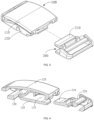
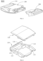
- the female buckle 100 includes a base 110, a cover plate 120, and an elastic member 130.
- the base 110 is mounted to fit the cover plate 120, and the elastic member 130 is arranged on one side of the cover plate 120 facing towards the base 110, wherein the cover plate 120 can swing relative to the base 110.
- One end of the cover plate 120 is pressed so that the elastic member 130 and the base 110 press each other, and the other end of the cover plate 120 swings in a direction away from the base 110.
- one side of the first guide block 122 away from the second guide block 123 is provided with a first position-limiting block 126
- one side of the second guide block 123 away from the first guide block 122 is provided with a second position-limiting block 127
- the first position-limiting block 126 and the second position-limiting block 127 are symmetrically arranged.
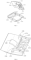
- the first position-limiting block 126 and the second position-limiting block 127 extend into the first position-limiting slot 1121 and the second position-limiting slot 1131, respectively.
- the first position-limiting block 126 and the second position-limiting block 127 rotate synchronously in the first position-limiting slot 1121 and the second position-limiting slot 1131 respectively, so that the two ends of the cover plate 120 swing relative to the base 110.
- the other end of the elastic member 130 abuts against the bottom plate 111.
- the elastic member 130 presses the bottom plate 111, and the side of the cover plate 120 away from the elasticity lifts in a direction away from the bottom plate 111, so that the position of the protrusion 121 changes accordingly.
- the male buckle 200 includes an insertion block 210 and a male buckle main body 220.
- the male buckle main body 220 is connected to the insertion block 210.
- One end of the insertion block 210 is recessed inward to form a recess 211, and the insertion block 210 is provided with an inclined surface 212.
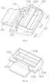
- the insertion block 210 is inserted into the insertion slot 115, and the protrusion 121 extends into the recess 211, so that the female buckle 100 and the male buckle 200 are fastened together.
- the male buckle main body 220 includes an opening frame 221, and the opening frame 221 includes a main frame block 2211, a first sub-frame block 2212, and a second sub-frame block 2213.
- Two ends of the main frame block 2211 are respectively connected to ends of the first sub-frame block 2212 and the second sub-frame block 2213, respectively.
- the other ends of the first sub-frame block 2212 and the second sub-frame block 2213 respectively extend towards a middle closing direction to form a first extension block 2214 and a second extension block 2215.
- Two side surfaces of the insertion block 210 are respectively connected to the first extension block 2214 and the second extension block 2215.
- the male buckle main body 220 further includes a connecting rod 2216, and the first sub-frame block 2212 and the second sub-frame block 2213 extend to one end to form a first abutting block 2217 and a second abutting block 2218. Two ends of the connecting rod 2216 are respectively connected to the first abutting block 2217 and the second abutting block 2218.
- the protrusion 121 abuts against the inclined surface 212 and moves along the inclined surface 212.
- the protrusion 121 is gradually lifted by the insertion block 210.
- the first position-limiting block 126 and the second position-limiting block 127 rotate in the slot.
- the side of the cover plate 120 close to the elastic member 130 downward-presses the elastic member 130 towards the bottom plate 111.
- the elastic member is restored from the deformation.
- the side of the cover plate 120 close to the male buckle 200 moves in the direction towards the base 110, and the cover plate 120 returns to its original position, thereby realizing fastening together of the male buckle 200 and the female buckle 100.
- the guide piece 1111 slides tightly close to a bottom surface of the insertion block 210 away from the inclined surface 212.
- the protrusion 121 is exactly embedded in the recess 211.
- the two ends of the guide piece 1111 respectively abut against the first extension block 2214 and the second extension block 2215.
- the first abutting block 2217 abuts against the first extension portion 1122 and the end portion of the cover plate 120
- the second abutting block 2218 abuts against the second extension portion 1132 and the end portion of the cover plate 120.
- the cover plate 120 when the cover plate 120 is pressed to close to one side of the elastic member 130, the elastic member 130 and the base 110 press each other, and the other side of the cover plate 120 will be lifted in the direction away from the bottom plate 111.
- the protrusion 121 is released from the recess 211, and at this moment, the male buckle 200 is pulled in the direction away from the female buckle 100, and the fastening relationship of the male buckle 200 and the female buckle 100 is released.
- one end of the lace may be tied to the connecting piece 114 of the female buckle 100, and of course may also be tied to other positions of the female buckle 100.
- the lace is tied to the connecting piece 114.
- the other end of the lace may be tied to the connecting rod 2216 or other positions of the male buckle 200, such as the main frame block 2211.
- the other end of the lace is tied to the connecting rod 2216.
Landscapes
- Buckles (AREA)
Claims (12)
- Boucle de ceinture (900), comprenant :une boucle femelle (100), comprenant une base (110) et une plaque de recouvrement (120), une fente d'insertion (115) étant prévue dans la base (110), la plaque de recouvrement (120) étant montée sur la base (110), la plaque de recouvrement (120) étant pourvue d'une saillie (121), la plaque de recouvrement (120) étant rotative par rapport à la base (110), et la boucle femelle (100) étant utilisée pour être reliée à une extrémité d'un lacet ;une boucle mâle (200), comprenant un bloc d'insertion (210) et un corps principal de boucle mâle (220), le corps principal de boucle mâle (220) étant relié au bloc d'insertion (210), un évidement (211) étant prévu dans l'extrémité du bloc d'insertion faisant face à la plaque de recouvrement, la boucle mâle (200) étant utilisée pour se raccorder à l'autre extrémité du lacet ; dans laquelle, lorsque le bloc d'insertion (210) est inséré dans la fente d'insertion (115), et la saillie (121) s'étend dans l'évidement (211), la boucle femelle (100) et la boucle mâle (200) sont fixées l'une à l'autre ; etun élément élastique (130) agencé sur l'extrémité de la plaque de recouvrement (120) à l'écart de la boucle mâle (200) ;dans laquelle, lorsque la plaque de recouvrement (120) est enfoncée, une extrémité de la plaque de recouvrement (120) se déplace vers la base (110), l'élément élastique (130) enfonce la base (110), et l'autre extrémité de la plaque de recouvrement (120) se soulève dans la direction s'éloignant de la base (110), de manière à amener la saillie à se séparer de l'évidement (211) ;dans laquelle la base (110) comprend une plaque inférieure (111), une première plaque latérale (112), une deuxième plaque latérale (113) et une pièce de liaison (114) ;deux côtés de la plaque inférieure (111) sont respectivement reliés à la première plaque latérale (112) et à la deuxième plaque latérale (113) pour former la fente d'insertion (115), deux extrémités de la pièce de liaison (114) sont respectivement reliées à la première plaque latérale (112) et à la deuxième plaque latérale (113), la pièce de liaison (114) et la plaque inférieure (111) sont agencées à un intervalle, et la pièce de liaison (114) est utilisée pour enrouler le lacet ;caractérisée en ce que la base (110) comprend en outre une tige protectrice (116), la première plaque latérale (112) et la deuxième plaque latérale (113) s'étendent vers l'extérieur vers une extrémité éloignée de la plaque inférieure (111) et sont reliées aux deux extrémités de la tige protectrice (116), et la tige protectrice (116) est située sur un côté de la base (110) à l'écart de la boucle mâle (200).
- Boucle de ceinture selon la revendication 1, dans laquelle la première plaque latérale (112) et la deuxième plaque latérale (113) sont en forme d'arc rond, et lorsque la plaque de recouvrement (120) recouvre la base (110), les extrémités de la première plaque latérale (112) et de la deuxième plaque latérale (113) à l'écart de la boucle mâle (200) sont agencées à une certaine distance de la plaque de recouvrement (120),
dans lequel, lorsque la plaque de recouvrement (120) est pressée, la plaque de recouvrement (120) est mobile dans une direction proche de la plaque inférieure (111), de manière à enfoncer l'élément élastique (130). - Boucle de ceinture selon la revendication 1, dans laquelle la première plaque latérale (112) s'étend partiellement dans une direction vers la deuxième plaque latérale (113) pour former une première plaque support (1123), la deuxième plaque latérale (113) s'étend partiellement dans une direction vers la première plaque latérale (112) pour former une deuxième plaque support (1133), la première plaque support (1123) et la deuxième plaque support (1133) sont agencées symétriquement à un intervalle, et la première plaque support (1123) et la deuxième plaque support (1133) sont toutes deux situées sur un côté de la base à l'écart du bloc d'insertion (210).
- Boucle de ceinture selon la revendication 1, dans laquelle une face d'extrémité de la plaque de recouvrement (120) faisant face à la base est partiellement étirée pour former un premier bloc de guidage (122) et un deuxième bloc de guidage (123), et le premier bloc de guidage (122) et le deuxième bloc de guidage (123) sont agencés à un intervalle de sorte qu'un canal est formé entre le premier bloc de guidage (122) et le deuxième bloc de guidage (123) ; et le bloc d'insertion (210) s'étend dans le canal de sorte que la saillie (121) est extensible dans l'évidement (211).
- Boucle de ceinture selon la revendication 4, dans laquelle la plaque de recouvrement (120) est en outre pourvue d'un bloc support (124), le bloc support (124) est logé dans le canal, et deux extrémités du bloc support sont reliées au premier bloc de guidage (122) et au deuxième bloc de guidage (123), respectivement.
- Boucle de ceinture selon la revendication 5, dans laquelle le bloc d'insertion (210) est pourvu d'une surface inclinée (212), une extrémité du bloc d'insertion (210) est partiellement évidée pour former l'évidement (211), et le premier bloc de guidage (122) et le deuxième bloc de guidage (123) sont tous les deux plus hauts que la saillie (121); et
lorsque le bloc d'insertion (210) est inséré vers le canal, la saillie (121) se déplace le long de la surface inclinée (212), une extrémité de la plaque de recouvrement (120) se déplace vers la plaque inférieure (111) et comprime l'élément élastique (130), et après l'extension de la saillie (121) dans l'évidement (211), l'élément élastique (130) déformé est détendu. - Boucle de ceinture selon la revendication 4, dans laquelle les parois latérales du premier bloc de guidage (122) et du deuxième bloc de guidage (123) sont respectivement pourvues d'un premier bloc de limitation de position (126) et d'un deuxième bloc de limitation de position (127), et la première plaque latérale (112) et la deuxième plaque latérale (113) sont respectivement pourvues d'une première fente de limitation de position (1121) et d'une deuxième fente de limitation de position (1131),
lorsque la plaque de recouvrement (120) recouvre la base (110), le premier bloc de limitation de position (126) s'étend dans la première fente de limitation de position (1121), le deuxième bloc de limitation de position (127) s'étend dans la deuxième fente de limitation de position (1131), une extrémité de la plaque de recouvrement (120) est enfoncée, et le premier bloc de limitation de position (126) et le deuxième bloc de limitation de position (127) tournent dans la première fente de limitation de position (1121) et la deuxième fente de limitation de position (1131), respectivement, de sorte que l'autre extrémité de la plaque de recouvrement (120) se soulève dans la direction s'éloignant de la base (110). - Boucle de ceinture selon l'une quelconque des revendications 1 à 7, dans laquelle le corps principal de boucle mâle (220) comprend un cadre d'ouverture (221), et le cadre d'ouverture (221) comprend un bloc cadre principal (2211), un premier sous-bloc cadre (2212) et un deuxième sous-bloc cadre (2213), deux extrémités du bloc cadre principal (2211) sont respectivement reliées à des extrémités du premier sous-bloc cadre (2212) et du deuxième sous-bloc cadre (2213), respectivement, les autres extrémités du premier sous-bloc cadre (2212) et du deuxième sous-bloc cadre (2213) s'étendent respectivement vers une direction de fermeture médiane pour former un premier bloc d'extension (2214) et un deuxième bloc d'extension (2215), deux surfaces latérales du bloc d'insertion (210) sont respectivement reliées au premier bloc d'extension (2214) et au deuxième bloc d'extension (2215), et lorsque le bloc d'insertion (210) est inséré dans la fente d'insertion (115), les parties d'extrémité du premier sous-bloc cadre (2212) et du deuxième sous-bloc cadre (2213) butent toutes deux contre la base (110).
- Boucle de ceinture selon la revendication 8, dans laquelle le corps principal de boucle mâle (220) comprend en outre une tige de liaison (2216), le premier sous-bloc cadre (2212) et le deuxième sous-bloc cadre (2213) s'étendent dans une direction s'éloignant de la base pour former un premier bloc de butée (2217) et un deuxième bloc de butée (2218), et deux extrémités de la tige de liaison (2216) sont respectivement reliées au premier bloc de butée (2217) et au deuxième bloc de butée (2218).
- Boucle de ceinture selon la revendication 8, dans laquelle une surface du bloc d'insertion (210) faisant face à la base est une surface inférieure du bloc d'insertion (210), les faces d'extrémité du premier sous-bloc cadre (2212) et du deuxième sous-bloc cadre (2213) à l'écart de la surface inférieure du bloc d'insertion (210) sont plus hautes que la surface inférieure du bloc d'insertion (210), et une extrémité de la base (110) proche de la boucle mâle (200) s'étend vers l'extérieur pour former une pièce de guidage (1111) ; et
lorsque le bloc d'insertion (210) est inséré dans la boucle femelle (100), une face d'extrémité de la pièce de guidage (1111) et la surface inférieure du bloc d'insertion coulissent l'une par rapport à l'autre, et la pièce de guidage (1111) s'insère entre le premier bloc d'extension (2214) et le deuxième bloc d'extension (2215). - Boucle de ceinture selon la revendication 9, dans laquelle les extrémités de la première plaque latérale (112) et de la deuxième plaque latérale (113) faisant face à la boucle mâle (200) s'étendent vers l'extérieur, formant respectivement une première partie d'extension (1122) et une deuxième partie d'extension (1132), et lorsque la boucle femelle (100) et la boucle mâle (200) sont fixées l'une à l'autre, la première partie d'extension (1122) et la deuxième partie d'extension (1132) butent respectivement contre le premier bloc de butée (2217) et le deuxième bloc de butée (2218).
- Ceinture, comprenant une boucle de ceinture (900) selon l'une quelconque des revendications 1 à 11 et un lacet, dans laquelle une extrémité du lacet est reliée à la boucle femelle et l'autre extrémité du lacet est reliée à la boucle mâle.
Applications Claiming Priority (2)
| Application Number | Priority Date | Filing Date | Title |
|---|---|---|---|
| CN202020780745.5U CN213154410U (zh) | 2020-05-12 | 2020-05-12 | 一种带扣及腰带 |
| PCT/CN2021/080577 WO2021227639A1 (fr) | 2020-05-12 | 2021-03-12 | Boucle de ceinture et ceinture |
Publications (3)
| Publication Number | Publication Date |
|---|---|
| EP4144251A1 EP4144251A1 (fr) | 2023-03-08 |
| EP4144251A4 EP4144251A4 (fr) | 2023-10-18 |
| EP4144251B1 true EP4144251B1 (fr) | 2025-01-22 |
Family
ID=75764816
Family Applications (1)
| Application Number | Title | Priority Date | Filing Date |
|---|---|---|---|
| EP21804554.0A Active EP4144251B1 (fr) | 2020-05-12 | 2021-03-12 | Boucle de ceinture et ceinture |
Country Status (6)
| Country | Link |
|---|---|
| US (1) | US12108846B2 (fr) |
| EP (1) | EP4144251B1 (fr) |
| JP (1) | JP3232696U (fr) |
| KR (1) | KR102743708B1 (fr) |
| CN (1) | CN213154410U (fr) |
| WO (1) | WO2021227639A1 (fr) |
Families Citing this family (2)
| Publication number | Priority date | Publication date | Assignee | Title |
|---|---|---|---|---|
| CN213154410U (zh) * | 2020-05-12 | 2021-05-11 | 香港多耐福有限公司 | 一种带扣及腰带 |
| USD1021687S1 (en) * | 2020-05-12 | 2024-04-09 | Duraflex Hong Kong Limited | Buckle |
Family Cites Families (18)
| Publication number | Priority date | Publication date | Assignee | Title |
|---|---|---|---|---|
| JPH0746167Y2 (ja) * | 1989-11-10 | 1995-10-25 | ワイケイケイ株式会社 | バックル |
| SE468195B (sv) * | 1991-03-04 | 1992-11-23 | Holmbergs Fab Ab Brdr | Laas till bilbaelte, saerskilt barnbaelte |
| JPH11309004A (ja) * | 1998-04-30 | 1999-11-09 | Ykk Corp | バックル |
| CN2380053Y (zh) * | 1999-08-04 | 2000-05-31 | 张正安 | 扳开式带扣 |
| JP3078238U (ja) * | 2000-03-15 | 2001-06-29 | 台灣扣具工業股▲ふん▼有限公司 | 織帯用バックル |
| JP3780497B2 (ja) * | 2001-09-25 | 2006-05-31 | フルヤ工業株式会社 | 合成樹脂製バックル |
| KR200405410Y1 (ko) * | 2005-10-12 | 2006-01-11 | 백남일 | 버클 |
| JP5134437B2 (ja) * | 2008-05-28 | 2013-01-30 | 株式会社ニフコ | バックル |
| CN201541856U (zh) * | 2009-11-11 | 2010-08-11 | 吉多思实业(深圳)有限公司 | 扣件 |
| CN102711545B (zh) * | 2009-12-25 | 2015-04-01 | Ykk株式会社 | 旁开扣及其锁定构件 |
| US8667651B2 (en) * | 2012-02-10 | 2014-03-11 | Ching-Wen Wang | Combined diving utensil |
| CN205018424U (zh) * | 2015-09-17 | 2016-02-10 | 台湾扣具工业股份有限公司 | 绳索扣 |
| CN205018422U (zh) * | 2015-09-17 | 2016-02-10 | 台湾扣具工业股份有限公司 | 绳索扣 |
| CN107713187A (zh) * | 2017-11-02 | 2018-02-23 | 洪佳泺 | 一种扣头 |
| CN208114135U (zh) * | 2018-03-13 | 2018-11-20 | 台湾扣具工业股份有限公司 | 绳带扣 |
| USD1021687S1 (en) * | 2020-05-12 | 2024-04-09 | Duraflex Hong Kong Limited | Buckle |
| CN213154410U (zh) * | 2020-05-12 | 2021-05-11 | 香港多耐福有限公司 | 一种带扣及腰带 |
| EP3915429B1 (fr) * | 2020-05-27 | 2023-12-27 | Pandora A/S | Fermoir de bijouterie |
-
2020
- 2020-05-12 CN CN202020780745.5U patent/CN213154410U/zh active Active
-
2021
- 2021-03-12 EP EP21804554.0A patent/EP4144251B1/fr active Active
- 2021-03-12 KR KR1020227042476A patent/KR102743708B1/ko active Active
- 2021-03-12 WO PCT/CN2021/080577 patent/WO2021227639A1/fr not_active Ceased
- 2021-04-20 JP JP2021001459U patent/JP3232696U/ja active Active
-
2022
- 2022-11-08 US US17/982,685 patent/US12108846B2/en active Active
Also Published As
| Publication number | Publication date |
|---|---|
| US20230073144A1 (en) | 2023-03-09 |
| EP4144251A4 (fr) | 2023-10-18 |
| KR20230008779A (ko) | 2023-01-16 |
| US12108846B2 (en) | 2024-10-08 |
| EP4144251A1 (fr) | 2023-03-08 |
| WO2021227639A1 (fr) | 2021-11-18 |
| JP3232696U (ja) | 2021-07-01 |
| KR102743708B1 (ko) | 2024-12-16 |
| CN213154410U (zh) | 2021-05-11 |
Similar Documents
| Publication | Publication Date | Title |
|---|---|---|
| US12108846B2 (en) | Belt buckle and belt | |
| EP3738460B1 (fr) | Boucle | |
| CN201541856U (zh) | 扣件 | |
| US5314763A (en) | Battery latch | |
| US20010054217A1 (en) | Back-clip structure | |
| CN209403730U (zh) | 搭扣 | |
| US8819960B2 (en) | Buckle | |
| US20240358123A1 (en) | Connecting Buckle with Safety Switch | |
| CN212177609U (zh) | 连接装置 | |
| CN109065397B (zh) | 一种具有复位功能的三位置钮子开关 | |
| CN106640869A (zh) | 锁紧装置 | |
| CN212257872U (zh) | 一种无线网卡用稳定性好的连接结构 | |
| US20130081236A1 (en) | Buckle assembly | |
| CN211649724U (zh) | 一种壁挂的自锁结构及具有自锁功能的壁挂 | |
| CN215075966U (zh) | 一种智能穿戴设备用连接结构及智能穿戴设备 | |
| CN109742604B (zh) | 一种拉环快速解锁装置以及快速解锁连接器 | |
| JPH049841Y2 (fr) | ||
| WO2023103262A1 (fr) | Boucle de liaison | |
| CN220654985U (zh) | 一种安全型背包卡扣 | |
| CN220966589U (zh) | 一种便于拆卸的滑动母扣 | |
| CN214064184U (zh) | 一种塑料软管接头 | |
| KR101531976B1 (ko) | 휴대단말기용 분리형 단말기커버 | |
| JPH09140431A (ja) | 携帯ソフトケース | |
| CN115251540B (zh) | 一种插扣 | |
| CN213992687U (zh) | 一种新型弹簧扣 |
Legal Events
| Date | Code | Title | Description |
|---|---|---|---|
| STAA | Information on the status of an ep patent application or granted ep patent |
Free format text: STATUS: THE INTERNATIONAL PUBLICATION HAS BEEN MADE |
|
| PUAI | Public reference made under article 153(3) epc to a published international application that has entered the european phase |
Free format text: ORIGINAL CODE: 0009012 |
|
| STAA | Information on the status of an ep patent application or granted ep patent |
Free format text: STATUS: REQUEST FOR EXAMINATION WAS MADE |
|
| 17P | Request for examination filed |
Effective date: 20221130 |
|
| AK | Designated contracting states |
Kind code of ref document: A1 Designated state(s): AL AT BE BG CH CY CZ DE DK EE ES FI FR GB GR HR HU IE IS IT LI LT LU LV MC MK MT NL NO PL PT RO RS SE SI SK SM TR |
|
| DAV | Request for validation of the european patent (deleted) | ||
| DAX | Request for extension of the european patent (deleted) | ||
| A4 | Supplementary search report drawn up and despatched |
Effective date: 20230915 |
|
| RIC1 | Information provided on ipc code assigned before grant |
Ipc: A44B 11/26 20060101ALI20230911BHEP Ipc: A44B 11/25 20060101AFI20230911BHEP |
|
| RIC1 | Information provided on ipc code assigned before grant |
Ipc: A44B 11/26 20060101ALI20240705BHEP Ipc: A44B 11/25 20060101AFI20240705BHEP |
|
| GRAP | Despatch of communication of intention to grant a patent |
Free format text: ORIGINAL CODE: EPIDOSNIGR1 |
|
| STAA | Information on the status of an ep patent application or granted ep patent |
Free format text: STATUS: GRANT OF PATENT IS INTENDED |
|
| INTG | Intention to grant announced |
Effective date: 20240902 |
|
| GRAJ | Information related to disapproval of communication of intention to grant by the applicant or resumption of examination proceedings by the epo deleted |
Free format text: ORIGINAL CODE: EPIDOSDIGR1 |
|
| STAA | Information on the status of an ep patent application or granted ep patent |
Free format text: STATUS: REQUEST FOR EXAMINATION WAS MADE |
|
| INTC | Intention to grant announced (deleted) | ||
| GRAP | Despatch of communication of intention to grant a patent |
Free format text: ORIGINAL CODE: EPIDOSNIGR1 |
|
| STAA | Information on the status of an ep patent application or granted ep patent |
Free format text: STATUS: GRANT OF PATENT IS INTENDED |
|
| GRAS | Grant fee paid |
Free format text: ORIGINAL CODE: EPIDOSNIGR3 |
|
| GRAA | (expected) grant |
Free format text: ORIGINAL CODE: 0009210 |
|
| STAA | Information on the status of an ep patent application or granted ep patent |
Free format text: STATUS: THE PATENT HAS BEEN GRANTED |
|
| INTG | Intention to grant announced |
Effective date: 20241204 |
|
| AK | Designated contracting states |
Kind code of ref document: B1 Designated state(s): AL AT BE BG CH CY CZ DE DK EE ES FI FR GB GR HR HU IE IS IT LI LT LU LV MC MK MT NL NO PL PT RO RS SE SI SK SM TR |
|
| REG | Reference to a national code |
Ref country code: GB Ref legal event code: FG4D |
|
| REG | Reference to a national code |
Ref country code: CH Ref legal event code: EP |
|
| REG | Reference to a national code |
Ref country code: IE Ref legal event code: FG4D |
|
| REG | Reference to a national code |
Ref country code: DE Ref legal event code: R096 Ref document number: 602021025180 Country of ref document: DE |
|
| P01 | Opt-out of the competence of the unified patent court (upc) registered |
Free format text: CASE NUMBER: APP_5024/2025 Effective date: 20250130 |
|
| REG | Reference to a national code |
Ref country code: SE Ref legal event code: TRGR |
|
| PGFP | Annual fee paid to national office [announced via postgrant information from national office to epo] |
Ref country code: AT Payment date: 20250417 Year of fee payment: 5 |
|
| REG | Reference to a national code |
Ref country code: NL Ref legal event code: MP Effective date: 20250122 |
|
| PG25 | Lapsed in a contracting state [announced via postgrant information from national office to epo] |
Ref country code: NL Free format text: LAPSE BECAUSE OF FAILURE TO SUBMIT A TRANSLATION OF THE DESCRIPTION OR TO PAY THE FEE WITHIN THE PRESCRIBED TIME-LIMIT Effective date: 20250122 |
|
| PG25 | Lapsed in a contracting state [announced via postgrant information from national office to epo] |
Ref country code: RS Free format text: LAPSE BECAUSE OF FAILURE TO SUBMIT A TRANSLATION OF THE DESCRIPTION OR TO PAY THE FEE WITHIN THE PRESCRIBED TIME-LIMIT Effective date: 20250422 |
|
| PG25 | Lapsed in a contracting state [announced via postgrant information from national office to epo] |
Ref country code: FI Free format text: LAPSE BECAUSE OF FAILURE TO SUBMIT A TRANSLATION OF THE DESCRIPTION OR TO PAY THE FEE WITHIN THE PRESCRIBED TIME-LIMIT Effective date: 20250122 |
|
| PG25 | Lapsed in a contracting state [announced via postgrant information from national office to epo] |
Ref country code: PL Free format text: LAPSE BECAUSE OF FAILURE TO SUBMIT A TRANSLATION OF THE DESCRIPTION OR TO PAY THE FEE WITHIN THE PRESCRIBED TIME-LIMIT Effective date: 20250122 |
|
| PG25 | Lapsed in a contracting state [announced via postgrant information from national office to epo] |
Ref country code: ES Free format text: LAPSE BECAUSE OF FAILURE TO SUBMIT A TRANSLATION OF THE DESCRIPTION OR TO PAY THE FEE WITHIN THE PRESCRIBED TIME-LIMIT Effective date: 20250122 |
|
| REG | Reference to a national code |
Ref country code: LT Ref legal event code: MG9D |
|
| PG25 | Lapsed in a contracting state [announced via postgrant information from national office to epo] |
Ref country code: IS Free format text: LAPSE BECAUSE OF FAILURE TO SUBMIT A TRANSLATION OF THE DESCRIPTION OR TO PAY THE FEE WITHIN THE PRESCRIBED TIME-LIMIT Effective date: 20250522 |
|
| REG | Reference to a national code |
Ref country code: AT Ref legal event code: MK05 Ref document number: 1760752 Country of ref document: AT Kind code of ref document: T Effective date: 20250122 |
|
| PG25 | Lapsed in a contracting state [announced via postgrant information from national office to epo] |
Ref country code: HR Free format text: LAPSE BECAUSE OF FAILURE TO SUBMIT A TRANSLATION OF THE DESCRIPTION OR TO PAY THE FEE WITHIN THE PRESCRIBED TIME-LIMIT Effective date: 20250122 |
|
| PG25 | Lapsed in a contracting state [announced via postgrant information from national office to epo] |
Ref country code: LV Free format text: LAPSE BECAUSE OF FAILURE TO SUBMIT A TRANSLATION OF THE DESCRIPTION OR TO PAY THE FEE WITHIN THE PRESCRIBED TIME-LIMIT Effective date: 20250122 Ref country code: PT Free format text: LAPSE BECAUSE OF FAILURE TO SUBMIT A TRANSLATION OF THE DESCRIPTION OR TO PAY THE FEE WITHIN THE PRESCRIBED TIME-LIMIT Effective date: 20250522 |
|
| PG25 | Lapsed in a contracting state [announced via postgrant information from national office to epo] |
Ref country code: GR Free format text: LAPSE BECAUSE OF FAILURE TO SUBMIT A TRANSLATION OF THE DESCRIPTION OR TO PAY THE FEE WITHIN THE PRESCRIBED TIME-LIMIT Effective date: 20250423 Ref country code: BG Free format text: LAPSE BECAUSE OF FAILURE TO SUBMIT A TRANSLATION OF THE DESCRIPTION OR TO PAY THE FEE WITHIN THE PRESCRIBED TIME-LIMIT Effective date: 20250122 |
|
| PGFP | Annual fee paid to national office [announced via postgrant information from national office to epo] |
Ref country code: CH Payment date: 20250401 Year of fee payment: 5 |
|
| PG25 | Lapsed in a contracting state [announced via postgrant information from national office to epo] |
Ref country code: AT Free format text: LAPSE BECAUSE OF FAILURE TO SUBMIT A TRANSLATION OF THE DESCRIPTION OR TO PAY THE FEE WITHIN THE PRESCRIBED TIME-LIMIT Effective date: 20250122 |
|
| PG25 | Lapsed in a contracting state [announced via postgrant information from national office to epo] |
Ref country code: SM Free format text: LAPSE BECAUSE OF FAILURE TO SUBMIT A TRANSLATION OF THE DESCRIPTION OR TO PAY THE FEE WITHIN THE PRESCRIBED TIME-LIMIT Effective date: 20250122 |
|
| PG25 | Lapsed in a contracting state [announced via postgrant information from national office to epo] |
Ref country code: DK Free format text: LAPSE BECAUSE OF FAILURE TO SUBMIT A TRANSLATION OF THE DESCRIPTION OR TO PAY THE FEE WITHIN THE PRESCRIBED TIME-LIMIT Effective date: 20250122 |
|
| PG25 | Lapsed in a contracting state [announced via postgrant information from national office to epo] |
Ref country code: MC Free format text: LAPSE BECAUSE OF FAILURE TO SUBMIT A TRANSLATION OF THE DESCRIPTION OR TO PAY THE FEE WITHIN THE PRESCRIBED TIME-LIMIT Effective date: 20250122 |
|
| PG25 | Lapsed in a contracting state [announced via postgrant information from national office to epo] |
Ref country code: IT Free format text: LAPSE BECAUSE OF FAILURE TO SUBMIT A TRANSLATION OF THE DESCRIPTION OR TO PAY THE FEE WITHIN THE PRESCRIBED TIME-LIMIT Effective date: 20250122 |
|
| PG25 | Lapsed in a contracting state [announced via postgrant information from national office to epo] |
Ref country code: CZ Free format text: LAPSE BECAUSE OF FAILURE TO SUBMIT A TRANSLATION OF THE DESCRIPTION OR TO PAY THE FEE WITHIN THE PRESCRIBED TIME-LIMIT Effective date: 20250122 Ref country code: EE Free format text: LAPSE BECAUSE OF FAILURE TO SUBMIT A TRANSLATION OF THE DESCRIPTION OR TO PAY THE FEE WITHIN THE PRESCRIBED TIME-LIMIT Effective date: 20250122 |
|
| REG | Reference to a national code |
Ref country code: DE Ref legal event code: R097 Ref document number: 602021025180 Country of ref document: DE |
|
| PG25 | Lapsed in a contracting state [announced via postgrant information from national office to epo] |
Ref country code: RO Free format text: LAPSE BECAUSE OF FAILURE TO SUBMIT A TRANSLATION OF THE DESCRIPTION OR TO PAY THE FEE WITHIN THE PRESCRIBED TIME-LIMIT Effective date: 20250122 |
|
| PG25 | Lapsed in a contracting state [announced via postgrant information from national office to epo] |
Ref country code: SK Free format text: LAPSE BECAUSE OF FAILURE TO SUBMIT A TRANSLATION OF THE DESCRIPTION OR TO PAY THE FEE WITHIN THE PRESCRIBED TIME-LIMIT Effective date: 20250122 |
|
| PG25 | Lapsed in a contracting state [announced via postgrant information from national office to epo] |
Ref country code: LU Free format text: LAPSE BECAUSE OF NON-PAYMENT OF DUE FEES Effective date: 20250312 |
|
| PLBE | No opposition filed within time limit |
Free format text: ORIGINAL CODE: 0009261 |
|
| STAA | Information on the status of an ep patent application or granted ep patent |
Free format text: STATUS: NO OPPOSITION FILED WITHIN TIME LIMIT |
|
| REG | Reference to a national code |
Ref country code: CH Ref legal event code: L10 Free format text: ST27 STATUS EVENT CODE: U-0-0-L10-L00 (AS PROVIDED BY THE NATIONAL OFFICE) Effective date: 20251203 |
|
| REG | Reference to a national code |
Ref country code: BE Ref legal event code: MM Effective date: 20250331 |
|
| GBPC | Gb: european patent ceased through non-payment of renewal fee |
Effective date: 20250422 |
|
| 26N | No opposition filed |
Effective date: 20251023 |
|
| PG25 | Lapsed in a contracting state [announced via postgrant information from national office to epo] |
Ref country code: GB Free format text: LAPSE BECAUSE OF NON-PAYMENT OF DUE FEES Effective date: 20250422 |
|
| PG25 | Lapsed in a contracting state [announced via postgrant information from national office to epo] |
Ref country code: BE Free format text: LAPSE BECAUSE OF NON-PAYMENT OF DUE FEES Effective date: 20250331 |
|
| PG25 | Lapsed in a contracting state [announced via postgrant information from national office to epo] |
Ref country code: IE Free format text: LAPSE BECAUSE OF NON-PAYMENT OF DUE FEES Effective date: 20250312 |
|
| REG | Reference to a national code |
Ref country code: CH Ref legal event code: U11 Free format text: ST27 STATUS EVENT CODE: U-0-0-U10-U11 (AS PROVIDED BY THE NATIONAL OFFICE) Effective date: 20260401 |
|
| PGFP | Annual fee paid to national office [announced via postgrant information from national office to epo] |
Ref country code: SE Payment date: 20260212 Year of fee payment: 6 |
|
| PGFP | Annual fee paid to national office [announced via postgrant information from national office to epo] |
Ref country code: NO Payment date: 20260216 Year of fee payment: 6 Ref country code: DE Payment date: 20260216 Year of fee payment: 6 |
|
| PGFP | Annual fee paid to national office [announced via postgrant information from national office to epo] |
Ref country code: FR Payment date: 20260212 Year of fee payment: 6 |