EP4144821A1 - Brandschutzvorrichtung und verfahren zu dessen herstellung - Google Patents
Brandschutzvorrichtung und verfahren zu dessen herstellung Download PDFInfo
- Publication number
- EP4144821A1 EP4144821A1 EP22189994.1A EP22189994A EP4144821A1 EP 4144821 A1 EP4144821 A1 EP 4144821A1 EP 22189994 A EP22189994 A EP 22189994A EP 4144821 A1 EP4144821 A1 EP 4144821A1
- Authority
- EP
- European Patent Office
- Prior art keywords
- fire protection
- protection device
- growth
- fire
- wall
- Prior art date
- Legal status (The legal status is an assumption and is not a legal conclusion. Google has not performed a legal analysis and makes no representation as to the accuracy of the status listed.)
- Granted
Links
Images

Classifications
-
- C—CHEMISTRY; METALLURGY
- C09—DYES; PAINTS; POLISHES; NATURAL RESINS; ADHESIVES; COMPOSITIONS NOT OTHERWISE PROVIDED FOR; APPLICATIONS OF MATERIALS NOT OTHERWISE PROVIDED FOR
- C09K—MATERIALS FOR MISCELLANEOUS APPLICATIONS, NOT PROVIDED FOR ELSEWHERE
- C09K21/00—Fireproofing materials
- C09K21/06—Organic materials
-
- E—FIXED CONSTRUCTIONS
- E04—BUILDING
- E04B—GENERAL BUILDING CONSTRUCTIONS; WALLS, e.g. PARTITIONS; ROOFS; FLOORS; CEILINGS; INSULATION OR OTHER PROTECTION OF BUILDINGS
- E04B1/00—Constructions in general; Structures which are not restricted either to walls, e.g. partitions, or floors or ceilings or roofs
- E04B1/62—Insulation or other protection; Elements or use of specified material therefor
- E04B1/92—Protection against other undesired influences or dangers
- E04B1/94—Protection against other undesired influences or dangers against fire
-
- C—CHEMISTRY; METALLURGY
- C08—ORGANIC MACROMOLECULAR COMPOUNDS; THEIR PREPARATION OR CHEMICAL WORKING-UP; COMPOSITIONS BASED THEREON
- C08L—COMPOSITIONS OF MACROMOLECULAR COMPOUNDS
- C08L1/00—Compositions of cellulose, modified cellulose or cellulose derivatives
- C08L1/02—Cellulose; Modified cellulose
-
- H—ELECTRICITY
- H02—GENERATION; CONVERSION OR DISTRIBUTION OF ELECTRIC POWER
- H02G—INSTALLATION OF ELECTRIC CABLES OR LINES, OR OF COMBINED OPTICAL AND ELECTRIC CABLES OR LINES
- H02G3/00—Installations of electric cables or lines or protective tubing therefor in or on buildings, equivalent structures or vehicles
- H02G3/02—Details
- H02G3/04—Protective tubing or conduits, e.g. cable ladders or cable troughs
- H02G3/0406—Details thereof
- H02G3/0412—Heat or fire protective means
-
- H—ELECTRICITY
- H02—GENERATION; CONVERSION OR DISTRIBUTION OF ELECTRIC POWER
- H02G—INSTALLATION OF ELECTRIC CABLES OR LINES, OR OF COMBINED OPTICAL AND ELECTRIC CABLES OR LINES
- H02G3/00—Installations of electric cables or lines or protective tubing therefor in or on buildings, equivalent structures or vehicles
- H02G3/02—Details
- H02G3/08—Distribution boxes; Connection or junction boxes
-
- H—ELECTRICITY
- H05—ELECTRIC TECHNIQUES NOT OTHERWISE PROVIDED FOR
- H05K—PRINTED CIRCUITS; CASINGS OR CONSTRUCTIONAL DETAILS OF ELECTRIC APPARATUS; MANUFACTURE OF ASSEMBLAGES OF ELECTRICAL COMPONENTS
- H05K5/00—Casings, cabinets or drawers for electric apparatus
-
- H—ELECTRICITY
- H02—GENERATION; CONVERSION OR DISTRIBUTION OF ELECTRIC POWER
- H02G—INSTALLATION OF ELECTRIC CABLES OR LINES, OR OF COMBINED OPTICAL AND ELECTRIC CABLES OR LINES
- H02G3/00—Installations of electric cables or lines or protective tubing therefor in or on buildings, equivalent structures or vehicles
- H02G3/02—Details
- H02G3/08—Distribution boxes; Connection or junction boxes
- H02G3/081—Bases, casings or covers
- H02G3/083—Inlets
Definitions
- the invention generally relates to a fire protection device which delimits a room on one or more sides and, in addition, one or more walls delimiting the room or a hollow body delimiting the room with a fire protection class with fire resistance of at least EI; EW 15 included.
- the invention relates in particular to a fire protection housing with a wall or a hollow body of fire resistance class EI; EW 15 or higher.
- the invention also relates to a method for producing such a fire protection device.
- a fire protection housing is a housing system made of combustible or non-combustible materials, which is used to maintain the function or to insulate electrical equipment against fire loads.
- Such fire protection housings are known as wall-mounted housings with at least one wall, in this case with a door, which is optionally embedded in a front wall or alone forms the front boundary of the room, or designed as free-standing housings or placed in front of a wall or niche are.
- the housing is formed by walls enclosing a volume on all sides.
- fire protection device is intended to denote devices in general that are used for fire protection and for this purpose have a fire protection behavior that is defined by the current fire protection standards. This includes both complex devices and their components. If there are common or defined terms for complex fire protection devices consisting of several components, these are used here, e.g. B. that Fire protection housing, fire protection distributor, safety housing, safety cabinet, hazardous materials cabinet or similar devices. The following statements on the design of the wall or the hollow body of a fire protection housing can also be applied analogously to these fire protection devices.
- Such fire protection devices and fire protection housings have various additional functional components which are included in the fire protection certificate for the device or the fire protection housing and serve the function of the relevant electrical device or its protection or partitioning in the event of a fire in the device.
- These include, for example, fasteners and/or connections of the wall elements, hinges, locking systems, cable bulkheads, smoke-tightness systems, ventilation, measuring systems for early smoke and fire detection, air-conditioning systems and others.
- the wall structure has at least three, but often more, heat-insulating and/or stable shells that form increasingly complex wall systems. These can be equipped with cooling devices and/or special coatings.
- the requirements for smoke tightness require special measures at points where two walls are to be connected to one another, such as a multi-stage structure with layers offset from one another, particularly in the area of wall openings, such as doors, ducts, for example for cables, ventilation systems or other, itumescent , ie coatings etc. that foam up under the influence of heat, in order to seal gaps so that they are smoke-tight.
- gypsum and thermal insulation boards and a very complex, costly wall construction.
- the sustainability of the product is another aspect of the invention, both with regard to the choice of material and the manufacturing process.
- a composite material is used for the one or more walls or the hollow body, hereinafter referred to collectively as the fire protection component, of a fire protection device, which has a cellulose material, e.g. organic cellulose material, as the volume-forming material of the composite.
- the cellulosic material is interspersed with the filamentous organism of a fungal mycelium which gives the cellulosic material the desired shape and strength.
- regionally available raw materials can be used.
- fire protection properties can also be realized for the cellulose material in connection with the filamentous organism.
- Such fire protection components can be fire-retardant EI; EW 15 to fire-resistant F90 and even F120.
- EI fire-retardant
- EW 15 to fire-resistant F90 and even F120.
- the requirements for the fire resistance of a fire protection device are specified in the European standard EN 13501-2 Part 2.
- Class E describes a space-enclosing function of the fire protection device and designation I or W refers to the insulation or thermal insulation that is sufficient to ensure a sufficiently strong heat barrier for the protection of people in the vicinity of the fire protection device in the event of a fire from one side for the relevant classification period, in the examples given 30, 90 or 120 minutes .
- cellulose fibers from woody and non-woody plants are used as cellulose material.
- regenerated cellulose or cellulose derivatives can also be used.
- Wood fibers, hemp, flax, cereal straw, corn straw, bamboo, flour or others are used as natural cellulose, the main component of plant cell walls. Waste from biogas plants can also be used.
- Regenerated cellulose fibers are fibers which, like those mentioned above, are produced from naturally occurring, renewable raw materials in chemical processes and are therefore not to be counted among the natural fibers.
- Cellulose derivatives are chemical derivatives of cellulose.
- Important properties such as density, structure, strength, stability, appearance and other properties, in particular fire resistance, can be varied by selecting a fiber type, fiber thickness and fiber length and/or a mixture of different cellulose fibers and/or fiber sizes.
- the filamentous organism of a fungal mycelium is characterized by filamentous growth into a substrate, here the cellulosic substrate.
- the substrate partially decomposes as a result of the growth.
- the filamentous organism is characterized by forming end-to-end multicellular assemblies. The entanglement of the filaments that occurs during growth forms a mat-like structure, which partially decomposes and traps the cellulose as a result of growth.
- the growth can be supported and regulated as well as stopped by the environmental conditions.
- a mycelium the root system of fungi, is suitable for growing into the cellulosic material within days to such an extent that the fire protection component for a fire protection device can be produced.
- Mushrooms from the Trametene genus for example, have proven advantageous for the desired fire protection properties.
- Such fungi belong to the lignin (a wood component) decomposing fungi.
- the real tinder fungus has proven to be beneficial for the manufacture of fire protection devices. Due to the wide range of cellulose fibers that can be used, various fungal mycelia can be used, with the combination of cellulose fibers and fungi that can be used depending on the desired fire protection properties being determined by tests.
- the material obtained in this way makes it possible, in particular, for the walls of the fire protection component to be designed in a single layer without loss of fire protection properties.
- the complex multi-layer structure with three or more layers that had to be connected to one another can be avoided.
- waste gypsum may come from plaster wall demolition or plasterboard manufacture and may be used including existing surface layers such as paper.
- Such additives usually have a single-digit volume proportion, based on the total volume, although higher volume proportions can also be advantageous depending on the cellulose material used, for example up to a proportion of 12% or 13% or 14% or 15%.
- tests with the cellulosic materials used are suitable in order to determine the optimum proportion for the individual case.
- the material mixture and thus the fire protection device produced from it can also be colored, for example in order to use the color to document the fire protection and/or material properties.
- a color design is possible through the choice of the type of cellulose fibers and/or through coloring additives.
- a fire protection component can be cut from a block of the composite material grown in this way.
- a mold is provided, the mold cavity of which has a geometry which corresponds to that of the desired fire protection component, optionally also the entire wall of a fire protection device or a coherent part thereof comprising several components.
- the density and also the fire protection behavior of the fire protection component can be actively influenced, since the density of the composite material increases with the continued growth of the fungal mycelium. Post-pressing can be used to further influence properties for both manufacturing variants.
- a further advantage of the growth of the filamentous organism into the cellulose material is the possibility of finally positioning necessary functional components of the fire protection device directly or with suitable aids in the mold and allowing them to grow in this way.
- Such functional components are, for example, hinges, locks, handles, connecting elements for related fire protection components of the same or other materials.
- the named functional components can have a structured outer contour, which improves durability in the spongy or tissue-like structures.
- Components with such contours are known, for example, from screw connections in which so-called screw anchors with a wide thread are larger Pitch are introduced into the structure.
- Feedthroughs for example by means of pipes, sleeves, hoses or other designs, for cables, ventilation, sensors or other things can be integrated into the growth, so that the structure of the fire protection component that is finally produced does not have to be influenced later, or only minimally, by incorporating such necessary components.
- the cellulosic material is uniformly mixed with the filamentous organism or with a precursor thereof from which such an organism can be formed.
- the spores can be used as a precursor and mixed with the cellulose fibers.
- wood shavings from an acacia are mixed with spores of the Pilsner varieties mentioned above.
- the mixing ratio can be determined by trial and error depending on the cellulose material and the type of mushroom.
- the duration of the mycelium growth up to the desired density of the component can be optimized via the proportion of spores
- a pasty mass is produced from this mixture with the addition of liquid, for example water, which has such a consistency that it can either be processed into a block or filled into a mold.
- liquid for example water
- This mixture is filled into a mold and exposed to the environmental conditions required for the growth of the filamentous organism, in particular with regard to temperature, humidity and light conditions.
- the mold is designed to be transparent, at least for the required wavelengths. In particular, these are wavelengths in the infrared range and in the visible light range.
- the environmental conditions during the growth of the filamentous organism are to be selected and, if necessary, determined by experiments in such a way that the composition of cellulosic material and root mycelium remains in a ratio, in particular volume ratio, required for the desired fire protection properties.
- the temperature can be set to values in the range from 20.degree. C. to less than 50.degree. C., preferably 25.degree. C. to 45.degree. C., more preferably 30.degree. C. to 40.degree . Previous tests can also be used to determine the favorable temperature. If sufficient data material is available from such tests, the mixture and the growth process can also be determined by means of simulation.
- temperatures in the range of approx. 20°C have proven to be optimal for the aforementioned mixture of wood chips and fungal spores.
- temperatures can be achieved, for example, under the effect of daylight with a high light intensity, in particular solar radiation, which has an illuminance in the range from approx. 20000 lx to approx. 90000 lx this temperature should be achievable in the core of the mass, so that the outside temperatures can definitely be higher.
- the humidity of the starting mass has a significant influence on the core temperature.
- temperatures above 50°C stop growth and, depending on the type of mycelium, can kill it.
- other heat sources can also be used with which the temperature ranges mentioned can be achieved. Using natural light, however, the energy balance of the process is significantly more favourable.
- components of the relevant fire protection device are arranged at the desired positions in the mold so that the sections of the components later located within the device protrude into the mold, the components are increasingly enclosed by the composite material as a result of mycelium growth.
- this can be hinges, fasteners for the fire door on the wall, door handles, passages through the door for cables, ventilation or the like, and possibly other components.
- the mycelium evenly decomposes and permeates the cellulosic material, solidifying it in the process.
- the growth process of the mycelium can be stopped by increasing the temperature.
- an increase to 50°C has proven to be beneficial.
- Higher values are possible and more efficient, with values in the range from 70°C to less than 100°C, preferably in the range from in the range from 75°C to less than 100°C, more preferably in the range from 80°C to less than 100° C have proven to be advantageous in order to safely stop the growth process in the core area of the component.
- the stable framework of the mycelium remains in place without losing its structure and stability. Only the fruiting body, in particular the spores of the fungus responsible for growth, are destroyed. The result is a composite material made of wood fibers with a carbon-containing support structure.
- the wall framework of the fire protection component with the integrated functional components can now be removed from the mold and completed with the necessary additional functional components to form a functional fire protection device.
- the latter relate, for example, to a locking system, connecting means, such as described below, hinges, wall installations, such as ventilation systems, cable bushings or similar, sensors and others.
- the composite material can be subsequently pressed.
- the pressing can take place in the mold in which the composite material was produced, or in a separate press after the fire protection component has been removed from the mold.
- the fire protection component according to the invention and the associated manufacturing process are sustainable, in particular due to the energy-saving manufacturing process and the starting materials used.
- the fire protection component can be composted after use, so that its non-compostable components made of metal or plastic can be easily separated, for example by sieving or by means of magnets.
- the proportion of the spores of the mycelium and the moisture of the starting mass both affect the essential properties of the finished material of the fire protection device as well as the duration and efficiency of the procedure, their discontinuation is essentially a question of optimizing the procedure.
- the fire protection housing according to 1 comprises four surrounding walls, namely two side walls 2, a front wall 3, in which a single-leaf door 4 is inserted, and a ceiling 5 and a floor 6.
- the door 4 is designed to be pivotable by means of hinges 7 and can be closed by means of a handle 8.
- a wall opening 9 is arranged in the ceiling, optionally or additionally also in other positions of the fire protection housing 1 . This is formed, for example, but not restrictively, by a duct housing into which the required installations are integrated or can be integrated later. Such wall passages are necessary, for example, for cable ducts, ventilation systems or other things.
- Such fire protection housings 1 regularly enclose an electrical distribution box (not shown), whose functional integrity is to be secured over a defined period of time in the event of a fire.
- All enclosing walls of the fire protection housing 1 and the door 4 are made of the composite building material according to the invention, described in more detail above.
- This comprises a mixture of various natural cellulose fibers with other additives, such as gypsum waste, the total proportion of which is in the single-digit percentage range, and a heat-treated material according to the above process description dead fungal mycelium of a fungus from the Trametene genus.
- all six sides of the fire protection housing 1 are designed in one piece, ie without the stepped connection between the separate walls that is necessary in the prior art. Only the door is a separate one component. If it were necessary to run one or more of the walls mentioned as separate walls and to connect them to the other walls manufactured according to the invention or to other existing walls, the composite material according to the invention is also suitable for the heat- and smoke-tight connections of walls or walls known from the prior art apply wall parts.
- the fire protection housing 1 shows a wall-mounted embodiment of a fire protection housing 1. This is permanently mounted on an existing fire-resistant wall 10.
- the fire protection housing 1 comprises a front wall 3, in which a double-leaf door 4 is arranged in the middle. Their door wings can be pivoted by means of hinges 7 and can be closed with handles.
- the fire protection housing 1 further comprises two side walls 2 and a ceiling (not shown) and a floor 6.
- the components of this fire protection housing 1 also consist of a composite material, as shown in FIG 1 described and are - optionally all -, with the exception of the two doors 4, made in one piece.
- the rear wall of the fire protection housing 1 is formed by the existing wall 10.
- the fire protection housing 1 is professionally connected to the wall 10 and the side walls 2, the floor 6 and the ceiling (not shown) by means of connecting means 11, for example by means of angle connectors, in a heat- and smoke-tight manner by means of screws 13 or the like.
- Those screws 13, which are screwed into the components of the fire protection housing 1, are received by holding elements 12, such as dowels with a spiral outer contour with wide webs, as are known, for example, from plasterboard dowels. Other variants of the holding elements are possible.
- the holding elements 12 were already incorporated into the composite material during the production of the fire protection housing 1 or the component.
- such externally contoured holding elements 12 in the composite material are shown schematically by a rectangle. Screws 13, which are inserted into the wall 10 using the usual dowels, are shown by lines to distinguish them.
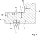
- the lateral connection of the two doors 4 to the front wall 3 is carried out professionally in a heat and smoke-tight manner using known from the prior art and in 3 step profiles shown as an example but not as a limitation.
- the central connection between the two doors 4 is designed to be heat and smoke-tight by means of known stepped profiles.
- the components of the door lock 14 to be introduced into the doors, their handles 8 or at least their connecting means (not shown) are already incorporated during the manufacture of the components of the fire protection housing 1 . Which components and/or connecting means these are depends on the closure used and can have a wide variety of designs.
- the step-shaped connection has, by way of example but not limitation, a three-step connection.
- Sealing means 16 known to those skilled in the art, for example intumescent coatings or lip seals or the like, are arranged on the surfaces of the steps which are perpendicular to the outside 15 of the door. Other designs and arrangements of the sealing means 16 are possible.
- connecting means 11 by means of the holding elements 12 as above 2 described, inserted. These can be used to reinforce the fire protection housing 1 or to mount internal fittings (not shown) of the fire protection housing 1 .
- the hinges 7 are also fastened in the composite material with screws (not shown) and the retaining elements 12 described above.
- the holding elements 12 are also prefabricated with the component.
- the walls of the fire protection housing according to the Figures 1 to 3 are produced with a thickness in the range from 80 to 100 mm using the method described above, the pH value of the pasty mass having a value of 6.
- the fungal mycelium was heated to 20°C in the core using daylight to stimulate the growth of the mycelium. Growth was arrested by core temperatures in the range of 80°C and the mycelium hardened.
- the housing and doors were released from the mold and using the prefabricated components to mount the doors to the one-piece housing wall and according to 2 mounted on the existing wall.
Landscapes
- Engineering & Computer Science (AREA)
- Chemical & Material Sciences (AREA)
- Architecture (AREA)
- Civil Engineering (AREA)
- Structural Engineering (AREA)
- Organic Chemistry (AREA)
- Health & Medical Sciences (AREA)
- Chemical Kinetics & Catalysis (AREA)
- Medicinal Chemistry (AREA)
- Polymers & Plastics (AREA)
- Materials Engineering (AREA)
- Microelectronics & Electronic Packaging (AREA)
- Physics & Mathematics (AREA)
- Electromagnetism (AREA)
- Building Environments (AREA)
Abstract
Description
- Die Erfindung betrifft allgemein eine Brandschutzvorrichtung, welche einen Raum ein- oder mehrseitig begrenzt und dazu eine oder mehrere den Raum begrenzende Wandungen oder einem den Raum begrenzenden Hohlkörper mit einer Brandschutzklasse mit Feuerwiderstand von mindestens EI; EW 15 umfasst. Die Erfindung betrifft insbesondere ein Brandschutzgehäuse mit einer Wandung oder einem Hohlkörper der Feuerwiderstandsklasse EI; EW 15 oder höher. Die Erfindung betrifft auch ein Verfahren zur Herstellung einer solchen Brandschutzvorrichtung.
- Als Brandschutzgehäuse wird ein Gehäusesystem aus brennbaren oder nicht brennbaren Materialien bezeichnet, welche dem Funktionserhalt oder der Brandlastdämmung von elektrischen Einrichtungen dienen. Derartige Brandschutzgehäuse sind als mit einer Wand verbundene Wandgehäuse bekannt mit zumindest einer Wandung, in diesem Fall mit einer Tür, die optional in eine Frontwandung eingelassen ist oder allein die frontseitige Begrenzung des Raumes bildet, oder als Standgehäuse freistehend ausgeführt oder vor eine Wand oder Nische gesetzt sind. Bei einem Standgehäuse wird das Gehäuse durch ein Volumen allseitig umschließende Wandungen gebildet.
- Nachfolgend soll der Begriff "Brandschutzvorrichtung" allgemein Vorrichtungen bezeichnen, welche dem Brandschutz dienen und zu diesem Zweck ein Brandschutzverhalten aufweisen, welches durch die gängigen Brandschutznormen festgelegt ist. Darunter zählen sowohl komplexe Vorrichtungen als auch deren Komponenten. Sofern es für komplexe, aus mehreren Komponenten bestehende Brandschutzvorrichtungen gängige oder festgelegte Begriffe gibt, werden diese hier verwendet, wie z. B. das Brandschutzgehäuse, Brandschutzverteiler, Sicherheitsgehäuse, Sicherheitsschrank, Gefahrstoffschrank oder vergleichbare Vorrichtungen. Die nachfolgenden Darlegungen zur Ausführung der Wandung oder des Hohlkörpers eines Brandschutzgehäuses sind analog auch auf diese Brandschutzvorrichtungen übertragbar.
- Derartige Brandschutzvorrichtungen und Brandschutzgehäuse weisen verschiedene ergänzende funktionale Komponenten auf, welche in den Brandschutznachweis der Vorrichtung bzw. des Brandschutzgehäuses einbezogen sind und der Funktion der betreffenden elektrischen Einrichtung bzw. deren Schutz oder Abschottung im Brandfall der Einrichtung dienen. Dazu gehören beispielsweise Befestigungsmittel und/oder Verbindungen der Wandelemente, Scharniere, Schließsysteme, Kabelschotts, Rauchdichtigkeitssystem, Be- und Entlüftungen, Messsysteme zur Rauch- und Brandfrüherkennung, Klimasysteme und andere.
- Gegenwärtig werden für den mehrschaligen Wandaufbau der Brandschutzvorrichtungen ein-, meist jedoch mehrschalige Gipsplatten mit Mineralfaser- oder anderen Wärmedämmplatten kombiniert, um die Anforderungen hinsichtlich Brandlast, Rauchdichtheit und Funktionserhalt zur erfüllen. Der Wandaufbau weist zumindest drei, häufig jedoch mehr wärmedämmende und/oder stabile Schalen auf, die zunehmend komplexere Wandsysteme bilden. Diese können mit Kühlvorrichtungen und/oder speziellen Beschichtungen ausgestattet sein. Insbesondere die Anforderungen der Rauchdichtheit erfordern an Stellen, an welchen zwei Wände miteinander zu verbinden sind, besondere Maßnahmen, wie ein mehrstufiger Aufbau mit zueinander versetzten Schichten, der insbesondere im Bereich von Wandöffnungen, wie Türen, Durchführungen beispielsweise für Kabel, Lüftungssystemen oder anderes, itumeszierende, d. h. unter Hitzeeinwirkung aufschäumende, Beschichtungen u. ä. auf, um Spalten rauchdicht zu verschließen. Im Ergebnis folgt ein zunehmender Bedarf an Gips- und Wärmedämmplatten und ein sehr komplexer, aufwendiger Wandaufbau.
- Auch wenn Gips recycelbar ist, ist dieser Rohstoff endlich, insbesondere aufgrund der Verbindung der Gipsbauteile als Verbund mit anderen Materialien beispielsweise als beschichtete und unbeschichtete Platten, welche aufwändig oder schwierig voneinander zu trennen sind.
- Es besteht daher der Bedarf nach einem nachhaltigen Ersatz für Mineralfaser- und Gipsplatten, welche für Brandschutzsysteme anwendbar und mit den notwendigen ergänzenden funktionalen Komponenten verbindbar sind, so dass das betreffende Brandschutzbauteil als solches die brandschutztechnischen Anforderungen und Tests erfüllt.
- Sowohl hinsichtlich der Materialauswahl als auch des Herstellungsprozesses ist die Nachhaltigkeit des Produkts ein weiterer Aspekt der Erfindung.
- Das Konzept der Erfindung kann dahingehend beschrieben werden, dass für die eine oder mehrere Wandungen oder den Hohlkörper, nachfolgend zusammenfassend auch als Brandschutzbauteil bezeichnet, einer Brandschutzvorrichtung ein Verbundmaterial verwendet wird, welches ein Cellulosematerial, z.B. organisches Cellulosematerial, als das volumenbildende Material des Verbunds aufweist. Das Cellulosematerial ist von dem filamentösen Organismus eine Pilzmyzeliums durchsetzt, welcher dem Cellulosematerial die gewünschte Form und Festigkeit verleiht. Bei der Auswahl des Cellulosewerkstoffs können vorwiegend regional verfügbare Ausgangsstoffe verwendet werden.
- Es wurde festgestellt, dass für das Cellulosematerial in Verbindung mit dem filamentösen Organismus darüber hinaus auch Brandschutzeigenschaften realisierbar sind. Derartige Brandschutzbauteile können feuerhemmend EI; EW 15 bis feuerbeständig F90 und sogar F120 ausgebildet werden. Die Anforderungen an den Feuerwiderstand einer Brandschutzvorrichtung sind in der Europäischen Norm EN 13501-2 Teil 2 festgelegt. Die Klasse E beschreibt eine raumabschließende Funktion der Brandschutzvorrichtung und die Bezeichnung I bzw. W betrifft die Isolation bzw., Wärmedämmung, die ausreichend ist, im für den betreffenden Klassifizierungszeitraum, in den angeführten Beispielen 30, 90 oder 120 Minuten, eine ausreichend starke Hitzebarriere zum Schutz von Menschen in der Nähe der Brandschutzvorrichtung bei einseitiger Brandbeanspruchung zu gewährleisten.
- Als Cellulosematerial kommen insbesondere Cellulosefaserstoffe von verholzenden und nichtverholzenden Pflanzen zur Anwendung. Alternativ oder in Kombination miteinander können auch Cellulose-Regenerate oder Cellulosederivate verwendet werden. Als natürliche Cellulose, dem Hauptbestandteil pflanzlicher Zellwände, kommen beispielsweise Holzfasern, Hanf, Flachs, Getreidestroh, Maisstroh, Bambus, Mehl oder andere zu Anwendung. Auch Abfälle aus Biogasanlagen sind verwendbar. Als Celluloseregenerate werden Fasern bezeichnet, welche wie auch die oben genannten aus natürlich vorkommenden, nachwachsenden Rohstoffen in chemischen Prozessen hergestellt werden und deshalb nicht zu den Naturfasern zu zählen sind. Cellulosederivate hingegen sind chemische Derivate von Cellulose.
- Über die Auswahl einer Faserart, die Faserdicke sowie Faserlänge und/oder einer Mischung aus verschiedenen Cellulosefasern und/oder Fasergrößen können wichtige Eigenschaften wie Dichte, Struktur, Festigkeit, Stabilität, Aussehen und weitere Eigenschaften, insbesondere der Feuerwiderstand, variiert werden.
- Der filamentöse Organismus eines Pilzmyzeliums ist durch ein fadenförmiges Wachstum in ein Substrat, vorliegend das Substrat aus Cellulose, gekennzeichnet. Das Substrat zersetzt sich infolge des Wachstums teilweise. Der filamentöse Organismus ist dadurch charakterisiert, dass er vielzellige End-to-End-Anordnungen bildet. Die während des Wachstums entstehende Verflechtung der Filamente bildet eine mattenartige Struktur, welche die Cellulose infolge des Wachstums teilweise zersetzt und einschließt. Das Wachstum kann durch die Umgebungsbedingungen unterstützt und reguliert werden sowie gestoppt werden.
- Ein Myzelium, das Wurzelwerk von Pilzen, ist geeignet, innerhalb von Tagen in einem solchen Umfang in das Cellulosematerial zu wachsen, dass das Brandschutzbauteil für eine Brandschutzvorrichtung herstellbar ist. Für die gewünschten Brandschutzeigenschaften haben sich beispielsweise Pilze aus der Gattung der Trameten als vorteilhaft erwiesen. Derartige Pilze gehören zu den Lignin (einem Holzbestandteil) abbauenden Pilzen. Beispielsweise hat sich der echte Zunderschwamm für die Herstellung von Brandschutzvorrichtungen als günstig erwiesen. Aufgrund der vielfältigen verwendbaren Cellulosefasern können verschiedene Pilzmyzelien zur Anwendung kommen, wobei in Abhängigkeit von den gewünschten Brandschutzeigenschaften die verwendbare Kombination von Cellulosefasern und Pilzen durch Versuche festzustellen ist.
- Das auf diese Art gewonnene Material gestattet es insbesondere, dass die Wandungen des Brandschutzbauteils einlagig ausgebildet werden können, ohne Verlust an Brandschutzeigenschaften. Der aufwändige mehrlagige Aufbau mit drei oder mehr Schichten, die miteinander zu verbinden waren, kann vermieden werden.
- Weitere für das Herstellungsverfahren vorteilhafte technologisch bedingte Zusatzstoffe zu den beiden Hauptbestandteilen sind möglich. So führen Zusätze von geschreddertem Abfallgips zu einer verbesserten Verarbeitung der Ausgangsmischung und damit verbunden zu einer höheren Feuerbeständigkeit und Stabilität. Der Abfallgips kann aus Rückbauten von Gipswänden oder der Herstellung von Gipsplatten stammen und kann einschließlich vorhandener Oberflächenschichten, beispielsweise Papier, verwendet werden. Derartige Zusätze weisen meist einen einstelligen Volumenanteil, bezogen auf das Gesamtvolumen, auf, wobei in Abhängigkeit von dem verwendeten Cellulosematerial auch höhere Volumentanteile von Vorteil sein können, beispielsweise bis zu einem Anteil von 12% oder 13% oder 14% oder 15%. Auch hier sind Versuche mit den verwendeten Cellulosmaterialien geeignet, um den optimalen Anteil für den Einzelfall zu ermitteln.
- Auch eine farbliche Gestaltung des Materialgemisches und damit der daraus hergestellten Brandschutzvorrichtung kann erfolgen, beispielsweise um mit der Farbe die Brandschutz- und/oder Materialeigenschaften zu dokumentieren. Eine farbliche Gestaltung ist durch die Wahl der Art der Cellulosefasern und/oder durch farbgebende Zusatzstoffe möglich.
- Ein Brandschutzbauteil kann aus einem auf diese Weise gewachsenen Block des Verbundmaterials geschnitten werden. Oder es wird eine Form bereitgestellt, deren Formhöhlung eine Geometrie aufweist, welche jener des gewünschten Brandschutzbauteils, optional auch der gesamten Wandung einer Brandschutzvorrichtung oder eines mehrere Bauteile umfassenden, zusammenhängenden Bestandteils davon entspricht. Bei der Verwendung einer Form kann die Dichte und auch das Brandschutzverhalten des Brandschutzbauteils aktiv beeinflusst werden, da mit fortgesetztem Wachstum des Pilzmyzeliums die Dichte des Verbundmaterials zunimmt. Durch ein Nach verpressen können Eigenschaften für beide Varianten der Herstellung weitergehend beeinflusst werden.
- Ein weiterer Vorteil des Wachstums des filamentösen Organismus in das Cellulosematerial besteht in der Möglichkeit, notwendige funktionale Komponenten der Brandschutzvorrichtung unmittelbar oder mit geeigneten Hilfsmitteln in der Form final zu positionieren und auf diese Weise einwachsen zu lassen. Solche funktionalen Komponenten sind beispielsweise Scharniere, Verschlüsse, Griffe, Verbindungselemente für zusammengehörige Brandschutzbauteile derselben oder anderer Materialien. Die benannten funktionalen Komponenten können eine strukturierte Außenkontur aufweisen, welche die Haltbarkeit in den schwamm- oder gewebeartigen Strukturen verbessern.
- Derartig konturierte Komponenten sind beispielsweise von Schraubverbindungen bekannt, bei denen sogenannte Schraubdübel mit breitem Gewinde großer Steigung in die Struktur eingebracht werden. Auch Durchführungen, beispielsweise mittels Rohren, Muffen, Schläuchen oder anderen Ausführungen, für Kabel, Belüftungen, Sensorik oder anderes sind in das Wachstum integrierbar, so dass die final erzeugte Struktur des Brandschutzbauteils nachträglich nicht oder nur minimal durch Einarbeiten derartiger notwendiger Komponenten beeinflusst werden muss.
- Zur Herstellung der Brandschutzvorrichtung wird das Cellulosematerial mit dem filamentösen Organismus oder mit einer Vorstufe davon, aus welcher sich ein solcher Organismus bilden lässt, gleichmäßig vermischt. Bei einem Pilzmyzelium sind die Sporen als Vorstufe verwendbar und mit den Cellulosefasern zu mischen. Beispielsweise werden Holzspäne einer Akazie mit Sporen der oben genannten Pilssorten vermischt. Das Mischungsverhältnis kann in Abhängigkeit vom Cellulosematerial und der Pilzsorte durch Versuche ermittelt werden. Über den Anteil der Sporen ist insbesondere die Dauer des Myzelwachstums bis zur gewünschten Dichte des Bauteils optimierbar
- Aus dieser Mischung wird unter Zugabe von Flüssigkeit, beispielsweise Wasser eine pastöse Masse hergestellt, welche eine solche Konsistenz aufweist, dass sie entweder zum Block verarbeitet oder in eine Form gefüllt werden kann.
- Es hat sich herausgestellt, dass der pH-Wert der pastösen Masse einen Einfluss auf das Pilzwachstum und daraus folgend die Funktionalität des Bauteils hat. Ein saurer pH-Wert, d.h. kleiner 7 hat sich als vorteilhaft herausgestellt. Da die Sporenzugabe die Masse saurer werden lässt und Werte im Bereich von 4 bis 6, bevorzugt von 5 bis 6 als Ausgangswert für die nachfolgende Behandlung vorteilhaft sind, Ist die Sporenzugabe und gegeben falls die Zugabe von Zusatzstoffen entsprechen zu wählen.
- Diese Mischung wird in eine Form gefüllt und dort den für das Wachstum des filamentösen Organismus erforderlichen Umgebungsbedingungen, insbesondere hinsichtlich Temperatur, Feuchtigkeit und Lichtverhältnissen, ausgesetzt. Zu diesem Zweck ist die Form zumindest für die benötigten Wellenlängen transparent ausgebildet. Das sind insbesondere Wellenlängen im Infrarotbereich und dem Bereich des sichtbaren Lichts. Die Umgebungsbedingungen während des Wachstums des filamentösen Organismus sind so auszuwählen und gegebenenfalls durch Versuche zu ermitteln, dass die Zusammensetzung aus Cellulosematerial und Wurzelmyzelium in einem für die gewünschten Brandschutzeigenschaften erforderlichen Verhältnis, insbesondere Volumenverhältnis, bleiben. Für die genannten Pilze der Gattung der Trameten und weitere verwendbare Pilzarten kann die Temperatur auf Werte im Bereich von 20°C bis kleiner 50°C, bevorzugt 25°C bis 45°C, weiter bevorzugt 30°C bis 40°C, eingestellt werden. Auch für die Ermittlung der günstigen Temperatur sind vorherige Versuche nutzbar. Liegt aus solchen Versuchen ausreichend Datenmaterial zur Verfügung kann die Mischung und der Wachstumsprozess auch mittels Simulation ermittelt werden.
- Für die zuvor genannte Mischung aus Holzspänen und Pilzsporen haben sich, je nach Wandungsdicke, Feuchtigkeit im pastösen Material und dem pH-Wert Temperaturen im Bereich von ca. 20°C als optimal herausgestellt.
- Diese Temperaturen ist beispielsweise unter Einwirkung von Tageslicht hoher Lichtintensität, insbesondere von Sonneneinstrahlung erzielbar, welche eine Beleuchtungsstärke im Bereich von ca. 20000 Ix bis ca. 90000 Ix aufweist, Bei der Einstellung der Temperatur ist zu berücksichtigen, dass für ein möglichst gleichmäßiges Durchwachsen der Ausgangsmasse diese Temperatur im Kern der Masse erzielbar sein sollte, so dass die Außentemperaturen durchaus höher liegen können, Die Feuchtigkeit der Ausgangsmasse hat einen deutlichen Einfluss auf die Kerntemperatur. Temperaturen über 50°C stoppen jedoch das Wachstum und können je nach Art des Myzeliums dieses abtöten. Anstelle des natürlichen Lichts können auch andere Wärmequellen verwendet werden, mit welchen die genannten Temperaturbereiche erzielbar sind. Mittels des natürlichen Lichts gestaltet sich die Energiebilanz des Verfahrens jedoch wesentlich günstiger.
- Werden, wie oben beschrieben, Komponenten der betreffenden Brandschutzvorrichtung an den gewünschten Positionen in der Form angeordnet, so dass die später innerhalb der Vorrichtung liegenden Abschnitte der Komponenten in die Form hineinragen, werden die Komponenten infolge des Myzelwachstums vom Materialverbund zunehmend fester umschlossen. Beispielsweise bei einer Brandschutztür, welche eine Ausnehmung innerhalb einer Trennwand eines Gebäudes verschließt, können das Scharniere, Befestigungsmittel der Brandschutztür an der Wand, Griffe der Tür, Durchlässe durch die Tür für Kabel, Lüftung o. ä. und gegebenenfalls weitere Komponenten sein.
- Während seiner Wachstumsphase zersetzt und durchsetzt das Myzelium das Cellulosematerial gleichmäßig und verfestigt es dabei. Ist die gewünschte Zusammensetzung des Verbundmaterials erreicht, kann der Wachstumsprozess des Myzeliums durch die Erhöhung der Temperatur gestoppt werden. Für die beispielhaft genannte Verwendung von Akazienholzfasern und dem echten Zunderschwamm hat sich eine Erhöhung auf 50°C als günstig erwiesen. Höhere Werte sind möglich und effizienter, wobei sich Werte im Bereich von 70°C bis kleiner 100°C, bevorzugt im Bereich von im Bereich von 75°C bis kleiner 100°C, weiter bevorzugt im Bereich von 80°C bis kleiner 100°C als vorteilhaft erwiesen haben, um auch im Kernbereich des Bauteils den Wachstumsprozess sicher zu stoppen, Bei den genannten Temperatur bleibt das stabile Gerüst des Myzeliums bestehen, ohne seine Struktur und Stabilität zu verlieren. Nur der Fruchtkörper, insbesondere die für das Wachstum sorgenden Sporen des Pilzes werden zerstört. Im Ergebnis ist ein Verbundmaterial aus Holzfasern mit einer karbonhaltigen Stützstruktur entstanden.
- Das Wandungsgerüst des Brandschutzbauteils mit den integrierten funktionalen Komponenten kann nunmehr aus der Form entnommen werden und mit erforderlichen weiteren funktionalen Bestandteilen zu einer funktionsgerechten Brandschutzvorrichtung komplettiert werden. Letztere betreffen je nach Art der Brandschutzvorrichtung beispielsweise ein Schließsystem, Verbindungsmittel, wie nachfolgend beschrieben, Scharniere, Wandeinbauten, wie Lüftungssysteme, Kabeldurchführungen o.ä., Sensorik und anderes.
- Gegebenenfalls kann, in Abhängigkeit von den gewählten Materialien und der gewünschten Dichte, eine nachträgliche Verpressung des Verbundmaterials erfolgen. Die Verpressung kann in der Form erfolgen, in welcher das Verbundmaterial hergestellt wurde, oder in einer separaten Presse, nach Entnahme des Brandschutzbauteils aus der Form.
- Das erfindungsgemäße Brandschutzbauteil und das zugehörige Herstellungsverfahren sind insbesondere durch den energieschonenden Herstellungsprozess sowie die verwendeten Ausgangsstoffe nachhaltig. Darüber hinaus ist das Brandschutzbauteil nach seiner Verwendung kompostierbar, so dass dessen nichtkompostierbaren Komponenten aus Metall oder Kunststoff einfach zu separieren sind, beispielsweise durch Sieben oder mittels Magneten.
- Da neben den verwendeten Zellulosefasern, bei denen aus Gründen der Nachhaltigkeit bevorzugt auf lokal verfügbare Rest-, Abfall- und/oder Recyclingmaterialien zurückgegriffen werden kann, der Anteil der Sporen des Myzeliums und die Feuchtigkeit der Ausgangsmasse sowohl auf die wesentlichen Eigenschaften des fertigen Materials der Brandschutzvorrichtung als auch auf die Dauer und Effizienz des Verfahrens wesentlichen Einfluss haben, ist deren Einstellung im Wesentlichen eine Frage der Optimierung des Verfahrens.
- Die Erfindung soll anhand eines Ausführungsbeispieles näher erläutert werden. Die zugehörigen Zeichnungen zeigen in
-
Fig. 1 eine Ausführungsform eines freistehenden Brandschutzgehäuses in perspektivischer Darstellung, -
Fig. 2 eine Ausführungsform eines wandständigen Brandschutzgehäuses in der Darstellung eines Horizontalschnitts und -
Fig. 3 das Detail A einer Ecke des Brandschutzgehäuses gemäßFig. 2 . - Die Figuren zeigen die Erfindung nur schematisch und in einem solchen Umfang, wie es für das Verständnis der Erfindung erforderlich ist. Sie erheben keinen Anspruch auf Vollständigkeit oder Maßstäblichkeit. Der Fachmann würde die in obiger Beschreibung und nachfolgend dargestellten Merkmale in weiteren Ausführungsformen miteinander kombinieren, soweit es ihm sinnvoll erscheint.
- Das Brandschutzgehäuse gemäß
Fig. 1 umfasst vier Umfassungswände, und zwar zwei Seitenwände 2, eine Frontwand 3, in welche eine einflügelige Tür 4 eingesetzt ist, und eine Decke 5 sowie einen Boden 6. Die Tür 4 ist mittels Scharnieren 7 schwenkbar gestaltet und mittels eines Handgriffs 8 verschließbar. In der Decke, optional oder ergänzend auch in anderen Positionen des Brandschutzgehäuses 1, ist ein Wanddurchlass 9 angeordnet. Dieser ist beispielhaft jedoch nicht beschränkend durch ein Kanalgehäuse gebildet, in welches die benötigten Einbauten integriert sind oder nachträglich integriert werden können. Derartige Wanddurchgänge sich beispielsweise für Kabeldurchführungen, Lüftungssysteme oder anderes erforderlich. - Derartige Brandschutzgehäuse 1 umschließen regelmäßig einen Elektroverteiler (nicht dargestellt), dessen Funktionserhalt im Brandfall über eine definierte Zeitspanne gesichert werden soll.
- Alle Umfassungswände des Brandschutzgehäuses 1 sowie die Tür 4 sind aus dem erfindungsgemäßen, oben näher beschriebenen Verbundbaustoff hergestellt, Dieser umfasst eine Mischung aus verschiedenen natürlichen Cellulosefasern mit weiteren Zusätzen, wie beispielsweise Gipsabfälle, deren Gesamtanteil im einstelligen Prozentbereich liegt, und einem durch Hitze gemäß obiger Verfahrensbeschreibung abgetöteten Pilzmyzelium eines Pilzes aus der Gattung der Trameten.
- Alle sechs Seiten des Brandschutzgehäuses 1 sind im Ausführungsbeispiel einteilig, d.h. ohne die im Stand der Technik notwendige Stufenverbindung zwischen den separaten Wänden, ausgebildet. Lediglich die Tür ist ein separates Bauteil. Sofern es erforderlich wäre, eine oder mehrere der genannten Wände als separate Wände auszuführen und mit den übrigen erfindungsgemäß gefertigten oder anderen vorhandenen Wänden zu verbinden, ist das erfindungsgemäßen Verbundmaterial auch geeignet, die aus dem Stand der Technik bekannten hitze- und rauchdichten Verbindungen von Wänden oder Wandteilen anzuwenden.
-
Fig. 2 zeigt eine wandständige Ausführungsform eines Brandschutzgehäuses 1. Dieses ist an einer bestehenden feuerbeständigen Wand 10 fest montiert. Das Brandschutzgehäuse 1 umfasst eine Frontwand 3, in welcher eine zweiflügelige Tür 4 mittig angeordnet ist. Deren Türflügel sind mittels Scharnieren 7 schwenkbar und Handgriffen verschließbar. - Das Brandschutzgehäuse 1 umfasst weiter zwei Seitenwände 2 und eine Decke (nicht dargestellt) sowie einen Boden 6. Auch die Bauteile dieses Brandschutzgehäuses 1 bestehen aus einem Verbundbaustoff, wie zu
Fig. 1 beschrieben und sind - optional alle -, mit Ausnahme der beiden Türen 4, einstückig hergestellt. - Die Rückwand des Brandschutzgehäuses 1 wird durch die bestehende Wand 10 gebildet. Zu diesem Zweck ist des Brandschutzgehäuse 1 mittels Verbindungsmitteln 11, beispielsweise mittels Winkelverbinder, mit der Wand 10 sowie den Seitenwänden 2, dem Boden 6 und der Decke (nicht dargestellt) fachmännisch hitze- und rauchdicht mittels Schrauben 13 oder ähnliches verbunden.
- Jene Schrauben 13, welche in die Bauteile des Brandschutzgehäuses 1 geschraubt sind, werden von Halteelementen 12 aufgenommen, wie beispielsweise Dübel mit einer spiralförmigen Außenkontor mit breiten Stegen, wie sie beispielsweise von Gipskartondübeln bekannt sind. Andere Varianten der Halteelemente sind möglich. Die Halteelemente 12 wurden, wie oben beschrieben, bereits bei der Herstellung des Brandschutzgehäuses 1 oder des Bauteils in das Verbundmaterial eingearbeitet. In der Darstellung in
Fig. 2 undFig. 3 sind derartig außenkonturierte Halteelemente 12 im Verbundmaterial schematisch durch ein Rechteck dargestellt. Schrauben 13, die unter Verwendung der üblichen Dübel in die Wand 10 eingebracht werden, sind zur Unterscheidung durch Linien dargestellt. - Der seitliche Anschluss der beiden Türen 4 an die Frontwand 3 erfolgt fachmännisch hitze- und rauchdicht mit aus dem Stand der Technik bekannten und in
Fig. 3 beispielhaft aber nicht beschränkend dargestellten Stufenprofilen. Auch die mittige Verbindung der beiden Türen 4 ist in Analogie dazu mittels bekannter Stufenprofilen hitze- und rauchdicht ausgeführt. - Auch die in die Türen einzubringenden Bestandteile des Türschlosses 14, dessen Handgriffe 8 oder zumindest deren Verbindungsmittel (nicht dargestellt) sind bereits bei der Herstellung der Bauteile des Brandschutzgehäuses 1 eingearbeitet. Welche Bestandteile und/oder Verbindungsmittel das sind, hängt von dem verwendeten Verschluss ab und kann verschiedenste Ausführungen haben.
-
Fig. 3 zeigt die Ausbildung der schwenkbaren Verbindung einer Tür 4 mit der Frontwand 3 und den sich daran anschließenden Eckbereich. Die stufenförmig ausgebildete Verbindung weist beispielhaft jedoch nicht beschränkend eine dreistufige Verbindung auf. An deren senkrecht zur Außenseite 15 der Tür liegenden Flächen der Stufen sind fachmännisch bekannte Dichtungsmittel 16 angeordnet, beispielsweise intumeszierende Beschichtungen oder Lippendichtungen oder ähnliches. Andere Ausführungen und Anordnungen der Dichtungsmittel 16 sind möglich. - Optional können im Inneren des Brandschutzgehäuses 1, beispielsweise in den Innenecken Verbindungsmittel 11 mittels der Halteelemente 12 wie oben zu
Fig. 2 beschrieben, eingefügt werden. Diese können der Aussteifung des Brandschutzgehäuses 1 oder der Montage von Inneneinbauten (nicht dargestellt) des Brandschutzgehäuses 1 dienen. - Die Scharniere 7 sind ebenfalls mit Schrauben (nicht dargestellt) und den oben beschriebenen Halteelementen 12 im Verbundmaterial befestigt. Die Halteelemente 12 sind im Ausführungsbeispiel ebenfalls mit dem Bauteil vorgefertigt.
- Die Wandungen der Brandschutzgehäuse nach den
Fig. 1 bis Fig. 3 sind mit einer Dicke im Bereich von 80 bis 100 mm mit dem oben beschriebenen Verfahren hergestellt, wobei der pH-Wert der pastösen Masse einen Wert von 6 aufweist. Das Pilzmyzelium wurde unter Ausnutzung von Tageslicht auf im Kern 20°C zur Anregung des Wachstums des Myzeliums erwärmt. Das Wachstum wurde mittels Kerntemperaturen im Bereich von 80°C gestoppt und das Myzelium verhärtet. Die Gehäuse und Türen wurden aus der Form gelöst und mittels der vorgefertigten Komponenten zur Montage der Türen an der einstückigen Gehäusewandung sowie gemäßFig. 2 an der bestehenden Wand montiert. -
- 1
- Brandschutzgehäuse
- 2
- Seitenwand
- 3
- Frontwand
- 4
- Tür
- 5
- Decke
- 6
- Boden
- 7
- Scharnier
- 8
- Handgriff
- 9
- Wanddurchführung
- 10
- Wand
- 11
- Verbindungsmittel
- 12
- Halteelemente
- 13
- Schrauben
- 14
- Türschloss
- 15
- Außenseite
- 16
- Dichtungsmittel
Claims (12)
- Brandschutzvorrichtung, welche einen Raum ein- oder mehrseitig begrenzt mit zumindest einer den Raum begrenzenden Wandung oder einem den Raum begrenzenden Hohlkörper, nachfolgend zusammenfassend als Brandschutzbauteil bezeichnet, welche zumindest einen Feuerwiderstand der Klasse EI; EW 15 aufweisen, dadurch gekennzeichnet, dass das Brandschutzbauteil aus einem Verbundmaterial besteht, welches Cellulosefasern als volumenbildenden Bestandteil, nachfolgend auch als Substrat bezeichnet, aufweist und dass das Volumen der Cellulosefasern von einem nicht mehr lebenden filamentösen Organismus eines Pilzmyzeliums durchsetzt ist.
- Brandschutzvorrichtung nach Anspruch 1, dadurch gekennzeichnet, dass als Cellulosefasern eine Art aus folgender Liste oder einer Mischung mehrerer Arten der Liste enthalten ist: Holzfasern, Hanf, Flachs, Getreidestroh, Maisstroh, Bambus, Mehl, Abfälle aus der Biovergasung, Cellulose-Regenerate, Cellulosederivate.
- Brandschutzvorrichtung nach einem der vorstehenden Ansprüche, dadurch gekennzeichnet, dass das Pilzmyzelium zumindest eine Art eines Lignin abbauenden Pilzes ist.
- Brandschutzvorrichtung nach einem der vorstehenden Ansprüche, dadurch gekennzeichnet, dass das Material des Brandschutzbauteils geschredderten oder gemahlenen Gips, bevorzugt von Abfallgips, als Zusatz umfasst.
- Brandschutzvorrichtung nach einem der vorstehenden Ansprüche, dadurch gekennzeichnet, dass die Wandung oder die Wandungen des Brandschutzbauteils einlagig und/oder das Brandschutzbauteil integral ausgebildet sind.
- Brandschutzvorrichtung nach einem der vorstehenden Ansprüche, dadurch gekennzeichnet, dass die Brandschutzvorrichtung ein Brandschutzgehäuse ist.
- Verfahren zur Herstellung einer Brandschutzvorrichtung nach einem der vorstehenden Ansprüche, folgende Verfahrensschritte in der angegebenen Reihenfolge umfassend:- Bereitstellung einer Mischung aus Cellulosefasern und Sporen eines Pilzes,- Herstellung eines pastösen Ausgangsmaterials aus der Cellulosefaser-Sporen-Mischung mittels Flüssigkeitszufuhr, derart dass das Ausgangsmaterial einen pH-Wert im Bereich von 4 bis 6 aufweist,- Einfüllen des pastösen Ausgangsmaterials in eine Form,- Erwärmung des Ausgangsmaterials auf eine Temperatur im Bereich von 20°C bis kleiner 50°C zur Anregung des Wachstums des Pilzmyzeliums,- Erwärmung des infolge des Wachstums des Pilzmyzeliums entstandenen Verbundmaterials auf eine Temperatur im Bereich von 50°C bis kleiner 100°C zur Beendigung des Wachstumsprozesses des Pilzmyzeliums, und- Entnahme des verfestigten Brandschutzbauteils aus der Form.
- Verfahren nach Anspruch 7, wobei die Temperaturen bei der ersten und/oder der zweiten Erwärmung im Kernbereich der Wandung erzeugt werden.
- Verfahren nach Anspruch 7 oder 8, wobei in einem weiteren Verfahrensschritt eine Verpressung des Verbundmaterials zur Erhöhung der Dichte des Verbundmaterials.
- Verfahren nach Anspruch 7 oder 8, wobei Komponenten, welche in dem oder an dem Brandschutzbauteil angeordnet werden sollen und der Funktion des Brandschutzbauteils dienen, auch als funktionale Komponenten bezeichnet, vor oder nach der Einfüllung des Ausgangsmaterials in die Form und vor dessen Erwärmung zur Wachstumsanregung in der Form positioniert werden.
- Verfahren nach Anspruch 9, wobei eine funktionale Komponente verwendet wird, welche an einer solchen Oberfläche eine Oberflächenstruktur aufweist, welche von dem Ausgangsmaterial bedeckt wird.
- Verfahren nach einem der Anspruch 7 bis 10, wobei zumindest die erste Erwärmung des Ausgangsmaterials mittels natürlichen Lichts erfolgt, wobei eine Form verwendet wird, welche transparent ist für zumindest den Wellenlängenbereich des Infrarot- und des sichtbaren Lichts.
Applications Claiming Priority (1)
| Application Number | Priority Date | Filing Date | Title |
|---|---|---|---|
| DE102021120921 | 2021-08-11 |
Publications (3)
| Publication Number | Publication Date |
|---|---|
| EP4144821A1 true EP4144821A1 (de) | 2023-03-08 |
| EP4144821C0 EP4144821C0 (de) | 2023-10-18 |
| EP4144821B1 EP4144821B1 (de) | 2023-10-18 |
Family
ID=82898926
Family Applications (1)
| Application Number | Title | Priority Date | Filing Date |
|---|---|---|---|
| EP22189994.1A Active EP4144821B1 (de) | 2021-08-11 | 2022-08-11 | Brandschutzvorrichtung und verfahren zu dessen herstellung |
Country Status (4)
| Country | Link |
|---|---|
| EP (1) | EP4144821B1 (de) |
| AT (1) | AT525330A3 (de) |
| DE (1) | DE102022120366A1 (de) |
| PL (1) | PL4144821T3 (de) |
Families Citing this family (1)
| Publication number | Priority date | Publication date | Assignee | Title |
|---|---|---|---|---|
| WO2024215576A1 (en) * | 2023-04-08 | 2024-10-17 | Mycocycle, Inc. | Volarization of gypsum material via mycoremediation |
Citations (2)
| Publication number | Priority date | Publication date | Assignee | Title |
|---|---|---|---|---|
| EP2993746A1 (de) * | 2014-09-05 | 2016-03-09 | Celsion Brandschutzsysteme GmbH | Transportables Brandschutzsystem für elektrische Anlagen |
| WO2021136883A1 (en) * | 2019-12-31 | 2021-07-08 | Teknologian Tutkimuskeskus Vtt Oy | Methods of making non-woven materials from mycelium |
-
2022
- 2022-08-11 PL PL22189994.1T patent/PL4144821T3/pl unknown
- 2022-08-11 DE DE102022120366.2A patent/DE102022120366A1/de active Pending
- 2022-08-11 EP EP22189994.1A patent/EP4144821B1/de active Active
- 2022-08-11 AT ATA50623/2022A patent/AT525330A3/de unknown
Patent Citations (2)
| Publication number | Priority date | Publication date | Assignee | Title |
|---|---|---|---|---|
| EP2993746A1 (de) * | 2014-09-05 | 2016-03-09 | Celsion Brandschutzsysteme GmbH | Transportables Brandschutzsystem für elektrische Anlagen |
| WO2021136883A1 (en) * | 2019-12-31 | 2021-07-08 | Teknologian Tutkimuskeskus Vtt Oy | Methods of making non-woven materials from mycelium |
Also Published As
| Publication number | Publication date |
|---|---|
| PL4144821T3 (pl) | 2024-03-18 |
| AT525330A3 (de) | 2026-01-15 |
| DE102022120366A1 (de) | 2023-02-16 |
| AT525330A2 (de) | 2023-02-15 |
| EP4144821C0 (de) | 2023-10-18 |
| EP4144821B1 (de) | 2023-10-18 |
Similar Documents
| Publication | Publication Date | Title |
|---|---|---|
| DE2052973A1 (de) | Vorsorgungszelle fur Wohneinheiten | |
| EP2390433A1 (de) | Fertigbauelemente und Herstellungsverfahren dafür | |
| EP4144821B1 (de) | Brandschutzvorrichtung und verfahren zu dessen herstellung | |
| AT506103B1 (de) | Brandschutzriegel und mit demselben gebildeter bauteil | |
| DE69913288T2 (de) | Vorgefertigter Wohnraum für ein Schiff und Installationsverfahren für einen solchen Wohnraum in einem Schiff | |
| EP3586050A1 (de) | Brandschutzelement | |
| EP1538297B1 (de) | Geteilte Feuerschutztüreinlage | |
| DE19541626A1 (de) | Dämmstoff und Verfahren zur Herstellung desselben | |
| EP3273556B1 (de) | Brandgeschützte rohr-/kabeldurchführung | |
| EP4237721A1 (de) | Verfahren zum brandschutzgerechten abdichten von leitungsdurchführungen dünner rohre, eine hierfür vorkonfektionierte dichtungsbaugruppe und verfahren zu deren herstellung | |
| DE3709654A1 (de) | Abschottung von rohbauoeffnungen in brandabschnittsbegrenzenden bauteilen | |
| EP2157063B1 (de) | Akustikputz | |
| DE10043355A1 (de) | Brandgeschützter Kabelkanal und Verfahren zur Herstellung desselben | |
| DE19520712C2 (de) | Haus mit Wandelementen und Verfahren zu dessen Herstellung | |
| DE102015212422B3 (de) | Modularer Fledermauskasten mit integrierter Isolierung | |
| EP1249547A2 (de) | Verfahren zur Herstellung eines Brandschutz-Bauelementes | |
| DE102018120957A1 (de) | Verfahren zum Herstellen von Feuerschutzabschlusselementen mit und ohne Verglasung sowie Feuerschutzabschlusselement und Feuerschutzabschlusselementserie | |
| DE29716408U1 (de) | Isolationselement für Sanitäreinrichtungen | |
| DE19848887C1 (de) | Wandbauelement und Anschlußdose | |
| AT511676B1 (de) | Verbundelement und verfahren zur herstellung eines verbundelementes | |
| DE202012104974U1 (de) | Dämmelement | |
| DE102005001796A1 (de) | Formteil für den Brandschutz und Verfahren zur Herstellung eines derartigen Formteils, sowie Baustoff für brandschutztechnische Formteile und Verfahren zur Herstellung eines derartigen Baustoffs | |
| DE10226784B4 (de) | Verfahren zur Herstellung eines Bauelements oder einer Schicht eines Verbundelementes | |
| DE19919896C1 (de) | Verfahren und Vorrichtung zur Kälteisolierung von Behältern insbesondere von Gärtanks | |
| DE10124467B4 (de) | Einblasbarer Dämmstoff für die Verwendung in Bauelementen und Verfahren zur Herstellung |
Legal Events
| Date | Code | Title | Description |
|---|---|---|---|
| PUAI | Public reference made under article 153(3) epc to a published international application that has entered the european phase |
Free format text: ORIGINAL CODE: 0009012 |
|
| STAA | Information on the status of an ep patent application or granted ep patent |
Free format text: STATUS: THE APPLICATION HAS BEEN PUBLISHED |
|
| AK | Designated contracting states |
Kind code of ref document: A1 Designated state(s): AL AT BE BG CH CY CZ DE DK EE ES FI FR GB GR HR HU IE IS IT LI LT LU LV MC MK MT NL NO PL PT RO RS SE SI SK SM TR |
|
| STAA | Information on the status of an ep patent application or granted ep patent |
Free format text: STATUS: REQUEST FOR EXAMINATION WAS MADE |
|
| 17P | Request for examination filed |
Effective date: 20230414 |
|
| RBV | Designated contracting states (corrected) |
Designated state(s): AL AT BE BG CH CY CZ DE DK EE ES FI FR GB GR HR HU IE IS IT LI LT LU LV MC MK MT NL NO PL PT RO RS SE SI SK SM TR |
|
| REG | Reference to a national code |
Ref country code: DE Ref legal event code: R079 Free format text: PREVIOUS MAIN CLASS: C09K0021060000 Ipc: H02G0003080000 Ref country code: DE Ref legal event code: R079 Ref document number: 502022000206 Country of ref document: DE Free format text: PREVIOUS MAIN CLASS: C09K0021060000 Ipc: H02G0003080000 |
|
| GRAP | Despatch of communication of intention to grant a patent |
Free format text: ORIGINAL CODE: EPIDOSNIGR1 |
|
| STAA | Information on the status of an ep patent application or granted ep patent |
Free format text: STATUS: GRANT OF PATENT IS INTENDED |
|
| RIC1 | Information provided on ipc code assigned before grant |
Ipc: C08L 1/02 20060101ALI20230616BHEP Ipc: H02G 3/04 20060101ALI20230616BHEP Ipc: C09K 21/06 20060101ALI20230616BHEP Ipc: H02G 3/08 20060101AFI20230616BHEP |
|
| INTG | Intention to grant announced |
Effective date: 20230711 |
|
| GRAS | Grant fee paid |
Free format text: ORIGINAL CODE: EPIDOSNIGR3 |
|
| GRAA | (expected) grant |
Free format text: ORIGINAL CODE: 0009210 |
|
| STAA | Information on the status of an ep patent application or granted ep patent |
Free format text: STATUS: THE PATENT HAS BEEN GRANTED |
|
| AK | Designated contracting states |
Kind code of ref document: B1 Designated state(s): AL AT BE BG CH CY CZ DE DK EE ES FI FR GB GR HR HU IE IS IT LI LT LU LV MC MK MT NL NO PL PT RO RS SE SI SK SM TR |
|
| REG | Reference to a national code |
Ref country code: GB Ref legal event code: FG4D Free format text: NOT ENGLISH |
|
| REG | Reference to a national code |
Ref country code: CH Ref legal event code: EP |
|
| REG | Reference to a national code |
Ref country code: IE Ref legal event code: FG4D Free format text: LANGUAGE OF EP DOCUMENT: GERMAN |
|
| REG | Reference to a national code |
Ref country code: DE Ref legal event code: R096 Ref document number: 502022000206 Country of ref document: DE |
|
| U01 | Request for unitary effect filed |
Effective date: 20231020 |
|
| U07 | Unitary effect registered |
Designated state(s): AT BE BG DE DK EE FI FR IT LT LU LV MT NL PT SE SI Effective date: 20231026 |
|
| PG25 | Lapsed in a contracting state [announced via postgrant information from national office to epo] |
Ref country code: GR Free format text: LAPSE BECAUSE OF FAILURE TO SUBMIT A TRANSLATION OF THE DESCRIPTION OR TO PAY THE FEE WITHIN THE PRESCRIBED TIME-LIMIT Effective date: 20240119 |
|
| PG25 | Lapsed in a contracting state [announced via postgrant information from national office to epo] |
Ref country code: IS Free format text: LAPSE BECAUSE OF FAILURE TO SUBMIT A TRANSLATION OF THE DESCRIPTION OR TO PAY THE FEE WITHIN THE PRESCRIBED TIME-LIMIT Effective date: 20240218 |
|
| PG25 | Lapsed in a contracting state [announced via postgrant information from national office to epo] |
Ref country code: ES Free format text: LAPSE BECAUSE OF FAILURE TO SUBMIT A TRANSLATION OF THE DESCRIPTION OR TO PAY THE FEE WITHIN THE PRESCRIBED TIME-LIMIT Effective date: 20231018 |
|
| PG25 | Lapsed in a contracting state [announced via postgrant information from national office to epo] |
Ref country code: IS Free format text: LAPSE BECAUSE OF FAILURE TO SUBMIT A TRANSLATION OF THE DESCRIPTION OR TO PAY THE FEE WITHIN THE PRESCRIBED TIME-LIMIT Effective date: 20240218 Ref country code: GR Free format text: LAPSE BECAUSE OF FAILURE TO SUBMIT A TRANSLATION OF THE DESCRIPTION OR TO PAY THE FEE WITHIN THE PRESCRIBED TIME-LIMIT Effective date: 20240119 Ref country code: ES Free format text: LAPSE BECAUSE OF FAILURE TO SUBMIT A TRANSLATION OF THE DESCRIPTION OR TO PAY THE FEE WITHIN THE PRESCRIBED TIME-LIMIT Effective date: 20231018 |
|
| PG25 | Lapsed in a contracting state [announced via postgrant information from national office to epo] |
Ref country code: RS Free format text: LAPSE BECAUSE OF FAILURE TO SUBMIT A TRANSLATION OF THE DESCRIPTION OR TO PAY THE FEE WITHIN THE PRESCRIBED TIME-LIMIT Effective date: 20231018 Ref country code: NO Free format text: LAPSE BECAUSE OF FAILURE TO SUBMIT A TRANSLATION OF THE DESCRIPTION OR TO PAY THE FEE WITHIN THE PRESCRIBED TIME-LIMIT Effective date: 20240118 Ref country code: HR Free format text: LAPSE BECAUSE OF FAILURE TO SUBMIT A TRANSLATION OF THE DESCRIPTION OR TO PAY THE FEE WITHIN THE PRESCRIBED TIME-LIMIT Effective date: 20231018 |
|
| REG | Reference to a national code |
Ref country code: DE Ref legal event code: R097 Ref document number: 502022000206 Country of ref document: DE |
|
| PG25 | Lapsed in a contracting state [announced via postgrant information from national office to epo] |
Ref country code: SK Free format text: LAPSE BECAUSE OF FAILURE TO SUBMIT A TRANSLATION OF THE DESCRIPTION OR TO PAY THE FEE WITHIN THE PRESCRIBED TIME-LIMIT Effective date: 20231018 |
|
| PG25 | Lapsed in a contracting state [announced via postgrant information from national office to epo] |
Ref country code: SM Free format text: LAPSE BECAUSE OF FAILURE TO SUBMIT A TRANSLATION OF THE DESCRIPTION OR TO PAY THE FEE WITHIN THE PRESCRIBED TIME-LIMIT Effective date: 20231018 Ref country code: SK Free format text: LAPSE BECAUSE OF FAILURE TO SUBMIT A TRANSLATION OF THE DESCRIPTION OR TO PAY THE FEE WITHIN THE PRESCRIBED TIME-LIMIT Effective date: 20231018 Ref country code: RO Free format text: LAPSE BECAUSE OF FAILURE TO SUBMIT A TRANSLATION OF THE DESCRIPTION OR TO PAY THE FEE WITHIN THE PRESCRIBED TIME-LIMIT Effective date: 20231018 |
|
| PLBE | No opposition filed within time limit |
Free format text: ORIGINAL CODE: 0009261 |
|
| STAA | Information on the status of an ep patent application or granted ep patent |
Free format text: STATUS: NO OPPOSITION FILED WITHIN TIME LIMIT |
|
| 26N | No opposition filed |
Effective date: 20240719 |
|
| U20 | Renewal fee for the european patent with unitary effect paid |
Year of fee payment: 3 Effective date: 20240829 |
|
| U1O | Appointed representative for the unitary patent procedure deleted after the registration of the unitary effect | ||
| U1N | Appointed representative for the unitary patent procedure changed after the registration of the unitary effect |
Representative=s name: HERTIN UND PARTNERRECHTS- UND PATENTANWAELTE PARTG MBB; DE |
|
| PG25 | Lapsed in a contracting state [announced via postgrant information from national office to epo] |
Ref country code: MC Free format text: LAPSE BECAUSE OF FAILURE TO SUBMIT A TRANSLATION OF THE DESCRIPTION OR TO PAY THE FEE WITHIN THE PRESCRIBED TIME-LIMIT Effective date: 20231018 |
|
| PG25 | Lapsed in a contracting state [announced via postgrant information from national office to epo] |
Ref country code: IE Free format text: LAPSE BECAUSE OF NON-PAYMENT OF DUE FEES Effective date: 20240811 |
|
| U20 | Renewal fee for the european patent with unitary effect paid |
Year of fee payment: 4 Effective date: 20250715 |
|
| PGFP | Annual fee paid to national office [announced via postgrant information from national office to epo] |
Ref country code: CH Payment date: 20250901 Year of fee payment: 4 |
|
| PGFP | Annual fee paid to national office [announced via postgrant information from national office to epo] |
Ref country code: CZ Payment date: 20250729 Year of fee payment: 4 |
|
| PG25 | Lapsed in a contracting state [announced via postgrant information from national office to epo] |
Ref country code: CY Free format text: LAPSE BECAUSE OF FAILURE TO SUBMIT A TRANSLATION OF THE DESCRIPTION OR TO PAY THE FEE WITHIN THE PRESCRIBED TIME-LIMIT; INVALID AB INITIO Effective date: 20220811 |
|
| PG25 | Lapsed in a contracting state [announced via postgrant information from national office to epo] |
Ref country code: HU Free format text: LAPSE BECAUSE OF FAILURE TO SUBMIT A TRANSLATION OF THE DESCRIPTION OR TO PAY THE FEE WITHIN THE PRESCRIBED TIME-LIMIT; INVALID AB INITIO Effective date: 20220811 |