EP4144902B1 - Dispositif de poste de filage avec emballage - Google Patents
Dispositif de poste de filage avec emballage Download PDFInfo
- Publication number
- EP4144902B1 EP4144902B1 EP22191904.6A EP22191904A EP4144902B1 EP 4144902 B1 EP4144902 B1 EP 4144902B1 EP 22191904 A EP22191904 A EP 22191904A EP 4144902 B1 EP4144902 B1 EP 4144902B1
- Authority
- EP
- European Patent Office
- Prior art keywords
- spindle
- brake
- encapsulation
- spinning
- position device
- Prior art date
- Legal status (The legal status is an assumption and is not a legal conclusion. Google has not performed a legal analysis and makes no representation as to the accuracy of the status listed.)
- Active
Links
Images

Classifications
-
- D—TEXTILES; PAPER
- D01—NATURAL OR MAN-MADE THREADS OR FIBRES; SPINNING
- D01H—SPINNING OR TWISTING
- D01H7/00—Spinning or twisting arrangements
- D01H7/02—Spinning or twisting arrangements for imparting permanent twist
- D01H7/04—Spindles
- D01H7/18—Arrangements on spindles for suppressing yarn balloons
-
- D—TEXTILES; PAPER
- D01—NATURAL OR MAN-MADE THREADS OR FIBRES; SPINNING
- D01H—SPINNING OR TWISTING
- D01H1/00—Spinning or twisting machines in which the product is wound-up continuously
- D01H1/14—Details
- D01H1/16—Framework; Casings; Coverings ; Removal of heat; Means for generating overpressure of air against infiltration of dust; Ducts for electric cables
- D01H1/162—Framework; Casings; Coverings ; Removal of heat; Means for generating overpressure of air against infiltration of dust; Ducts for electric cables for ring type
-
- D—TEXTILES; PAPER
- D01—NATURAL OR MAN-MADE THREADS OR FIBRES; SPINNING
- D01H—SPINNING OR TWISTING
- D01H4/00—Open-end spinning machines or arrangements for imparting twist to independently moving fibres separated from slivers; Piecing arrangements therefor; Covering endless core threads with fibres by open-end spinning techniques
- D01H4/42—Control of driving or stopping
- D01H4/44—Control of driving or stopping in rotor spinning
-
- D—TEXTILES; PAPER
- D01—NATURAL OR MAN-MADE THREADS OR FIBRES; SPINNING
- D01H—SPINNING OR TWISTING
- D01H1/00—Spinning or twisting machines in which the product is wound-up continuously
- D01H1/14—Details
- D01H1/42—Guards or protectors for yarns or threads, e.g. separator plates, anti-ballooning devices
- D01H1/427—Anti-ballooning cylinders, e.g. for two-for-one twist machine
-
- D—TEXTILES; PAPER
- D01—NATURAL OR MAN-MADE THREADS OR FIBRES; SPINNING
- D01H—SPINNING OR TWISTING
- D01H13/00—Other common constructional features, details or accessories
- D01H13/08—Twist arresters
-
- D—TEXTILES; PAPER
- D01—NATURAL OR MAN-MADE THREADS OR FIBRES; SPINNING
- D01H—SPINNING OR TWISTING
- D01H4/00—Open-end spinning machines or arrangements for imparting twist to independently moving fibres separated from slivers; Piecing arrangements therefor; Covering endless core threads with fibres by open-end spinning techniques
- D01H4/48—Piecing arrangements; Control therefor
- D01H4/50—Piecing arrangements; Control therefor for rotor spinning
Definitions
- the invention relates to a spinning station device for a ring spinning machine comprising a spindle for a bobbin which is mounted on a spindle bank in a rotationally drivable manner and an encapsulation which runs in the longitudinal direction of the spindle and encloses the bobbin.
- Machines for spinning processes with closed end and true twist such as ring spinning, funnel spinning, loop spinning, spinning with rotating rings, spinning with floating rings, spinning with balloon limitations of all kinds (multi-balloon, balloon constriction sleeves standing and moving, balloon reductions such as spinning crowns, spinning fingers, balloon constriction rings, etc.), pot spinning, Murano spinning, are well known.
- Thread is the generic term for yarn, filament and twisted yarn. In the following, we will generally refer to “yarn” and “spinning”. However, the expert knows that the terms can also apply to “thread” and “twisting”.
- the reason for the exponential increase in energy consumption is that in closed-end spinning processes with simple true twist, the winding packages on the machine must be rotated (otherwise the machine would have to be rotated around the package).
- the package body usually in the form of a cop, then acts as a fan.
- Encapsulations are known for the purpose of saving energy by reducing the air mass to be accelerated.
- the cop and/or the thread balloon are usually encapsulated in a cylindrical sleeve whose diameter is a few millimeters larger than the cop or the balloon. This works, but hinders access to the cop in various operating situations, such as when repairing a thread break or when piecing.
- a special form of balloon encapsulation is the balloon constriction sleeve, as used for example in DE1510657B1 or DE19848752A1 described.
- the spool or cop rotates on the axis of a spindle and is connected to it, for example, by friction.
- the spindle can be driven by a belt drive or by a single motor.
- the spindles are usually attached to a spindle bank. This can be fixed or movable in the axial direction of the spindle.
- a relative movement in the axial direction of the bobbin (or spindle) must be realized between this and an element for defining the thread laying, so that not all of the yarn is wound up in the same place as a bead, but in a bobbin structure shape that can be determined by the relative movement (e.g. as a cop winding).
- Organs for laying the thread include, for example, the ring and traveller, the bell or funnel edge in bell, funnel or loop spinning or a thread guide in funnel or Murano spinning, thread guide tubes or similar.
- the elements for laying the thread are usually attached next to each other on a long element, which, depending on the element, is called a ring, funnel, bell or thread guide bank or frame.
- the relative movement can be achieved by moving one or both elements relative to each other.
- the ring rail is moved and the spindle rail is fixed to the machine frame.
- Encapsulations can be attached to the ring rail, as shown in CH683349A5 (and DE1510657B1 or DE19848752A1 ), whereby only a certain, small part of the spinning area is encapsulated. The energy savings are small.
- CN209957949U shows an incomplete encapsulation that is installed below the ring rail, but shows an upwardly displaced, extended attachment of the spindle with a single motor drive.
- the encapsulation is not complete and the spindle is relatively unstable, whereby the air gap of the external rotor cannot be kept constant due to the precession of the spindle.
- CH706759A1 shows an enclosure that completely and efficiently encapsulates the cop below the ring rail, but the drive and bearing construction of the spindle is inconveniently long to allow the spindle to plunge into the enclosure.
- DE1685679A1 shows two different encapsulation variants that can be shortened, but they do not have the optimal diameter for energy along their entire length, nor are they stable, dirt-resistant and easy to clean. In addition, they do not offer easy accessibility.
- EP3483313A1 describes a moving spindle bank, whereby the spindle moves into the enclosure.
- a complex, long spindle shape is necessary.
- WO2020105006A1 describes a long, magnetically mounted spindle that is suitable for moving into an enclosure attached to a ring rail. The effort required to use the enclosure is considerable.
- CH715908A1 shows a multi-balloon process with a fixed ring bank and a moving spindle bank, which allows the majority of the balloons to be kept constant.
- the great effort and enormous construction height required to encapsulate both the balloon above the ring bank and the cop below the spindle can also be seen.
- the energy savings are also reduced due to the large, rotating air volume.
- JP2013170337A describes a spinning machine in which the casing is permanently attached to the spindle bank.
- the casing is slotted and the functional part of the ring bank is attached to the inside of the machine, behind the casing, so that the ring holder of the ring bank reaches through the slot from the outside and the ring is guided axially within the casing.
- the machine structure is essentially conventional and the casing is only as high as the function requires, but among other disadvantages, the accessibility of the spinning station is poor.
- the spinning machine is difficult to operate in certain operating situations. In any case, the spinning station must be stopped and made accessible in certain operating situations, such as a thread break or when piecing onto the bare tube.
- CN210194054U solves the problem of integrating the thread guide and guides the spinning ring by magnets held from the outside within the encapsulation, without the need for a slot.
- the thread guide is integrated into the cover and the height is optimized.
- the Encapsulation rotates and would require encapsulation itself to save energy.
- the technical effort is high.
- the spinning station is very difficult to access.
- the spindle must be started with a fully twisted thread.
- the thread receives additional twists in the same piece of yarn, which can lead to the thread being over-twisted and breaking if the piecing is too slow or the spinning speed is too fast.
- One object of the present invention is to enable complete encapsulation of a spindle or a bobbin, which allows simple access to the spindle, compatible with the design of a conventional ring spinning machine.
- a further object is to enable accessibility with simple operation of an individual spinning station, especially in the event of a thread break. In particular, it should be possible to repair a thread break in the 6 to 10 seconds that are usual today.
- This object is achieved by a spinning station device with the features of claim 1.
- the spinning station device for a ring spinning machine comprises a spindle for a bobbin (i.e.
- a bare tube or a bobbin with wound yarn that is mounted on a spindle bank in a rotationally drivable manner and an encapsulation that runs in the longitudinal direction of the spindle and encloses the bobbin, the encapsulation being connected to the spindle bank.
- the encapsulation is divided in the longitudinal direction and has a rear capsule wall and a front, operator-side capsule wall. The front capsule wall can be moved into an open position so that in the open position the bobbin of the spinning station device is accessible for operation.
- the front capsule wall can be pivotally connected at a lower region and can be pivoted into a preferably horizontal position.
- the front capsule wall can be brought into an open position by a linear movement, by pivoting about the spindle axis or by a sliding movement or the like.
- the invention has the advantage that the encapsulation can be opened very easily.
- a ring spinning machine the axes of rotation of the spindles in the individual spinning stations run vertically.
- the spindles are mounted on a spindle bank at the lower end so that they can be driven in rotation.
- As the front, operator-side encapsulation wall is mounted so that it can rotate at the lower end, it can reliably ensure that the spool body is accessible from the front, i.e. from the operator side of the ring spinning machine, when it is swung out from a vertical, closed position to a horizontal, open position, so that machine piecing or automatic or manual operation in the event of a thread break is possible without any problems.
- Such encapsulation is also suitable for retrofitting existing spinning machines.
- the rear capsule wall can be firmly connected to the spindle bank and the front capsule wall can be pivotally connected to the rear capsule wall.
- the rear capsule wall can, for example, have two laterally arranged and forward-projecting legs on which the front capsule wall is pivotally held, e.g. by means of an axis.
- the front capsule wall can also be pivotally connected to the spindle bank, or to a holder attached to the spindle bank.
- the rear capsule wall and the front capsule wall can each be designed as a partial shell, which are preferably connected to one another with a hinge in the area of the spindle bank. Together, the partial shells enclose 360° of the spindle axis.
- the partial shells can be designed as two half shells, each of which encloses 180°. Other divisions are also conceivable.
- the spinning station device also has a spindle brake, which can be actuated by opening the encapsulation in order to brake the spindle or the bobbin.
- a spindle brake which can be actuated by opening the encapsulation in order to brake the spindle or the bobbin.
- Such a mechanical spindle brake is often necessary because the bobbins can no longer be braked by hand due to the high speed. Reliable, fast braking is also necessary, for example, to repair a thread break in the shortest possible time.
- Spindle brakes are known per se and are usually designed in such a way that they can be operated by the operator with the knee, so that both hands are free to repair the thread breakage.
- the front capsule wall can have a brake actuation device that actuates the spindle brake by moving the front capsule wall into the open position.
- a brake actuation device that actuates the spindle brake by moving the front capsule wall into the open position.
- the spindle brake is controllable in its braking force.
- the spindle brake can be infinitely controlled in its braking force. With a controllable braking force, the spindle can be braked quickly or slowly to a standstill as required. Conversely, the start-up of the spindle can be regulated by closing the enclosure or the front enclosure wall, so that the spindle has the speed required for spinning.
- the braking effect of the spindle brake can increase with increasing degree of opening of the encapsulation up to a maximum braking effect.
- the spindle brake can be actuated via the brake actuation device attached to the front capsule wall.
- the spindle brake and the brake actuation device can be designed in such a way that the braking effect increases with increasing degree of opening of the encapsulation.
- the spindle or the bobbin is braked.
- the braking effect decreases and the spindle or the bobbin begins to rotate again.
- the front capsule wall acts like a brake lever to regulate the speed of the spindle.
- the start-up of the spindle can be regulated, especially when the encapsulation is closed, so that the optimal speed for twisting in the yarn at the end of the thread break repair is achieved.
- the spindle runs again at the operating speed and the spinning process continues.
- the spindle brake may be arranged between the bobbin and the whorl or between the whorl and the bobbin bearing.
- the spindle brake can be designed in the form of a clamp or pliers.
- the clamp can have a first brake lever and a second brake lever, which are connected to one another via a hinge.
- One of the brake levers can also be designed to be spring-loaded.
- a clamping jaw for braking the spindle can be formed at one end of each of the two brake levers, which are placed around the spindle for this purpose.
- the other end of the two brake levers can be designed in such a way that the brake actuation device can be inserted between the two brake levers and presses these ends of the brake levers apart. The clamping jaws are pressed together and brake the spindle.
- the two brake levers can have slanted stop surfaces at the end into which the brake actuation device is inserted (i.e. the end facing away from the spindle), which approach the hinge.
- the braking effect can increase as the encapsulation is opened or the brake actuation device is inserted between the brake levers. From a predetermined insertion depth, the two stop surfaces can run parallel to one another, so that if the brake actuation device is inserted further, the braking effect no longer increases but remains constant. This is particularly advantageous if a spindle decoupling device as described below is also used.
- the spindle brake e.g. with a brake shoe and a guide rail for a brake actuation device of the encapsulation, are also possible.
- the guide rail can be designed in such a way that the braking effect increases depending on the degree of opening of the encapsulation and is kept constant if necessary from a certain degree of opening.
- Spinning actuators can be provided with individual spindle drive units, or one drive unit can drive several spinning actuators, for example via a drive belt.
- the spinning station device can have a single spindle drive unit that can be controlled by opening or closing the encapsulation (similar to the spindle brake described).
- the spinning station device can be provided with a drive control unit that can be actuated by opening and closing the encapsulation.
- opening the encapsulation the speed of the drive device can be reduced or the drive device can be switched off completely.
- closing the encapsulation the speed of the drive device can be increased or the drive device can be switched on again.
- the control system can be mechanical and/or electronic.
- the spinning station device can have a spindle decoupling device which decouples a drive element of the ring spinning machine from the spindle by opening the capsule, preferably when the front capsule wall is swung out into the open position.
- the drive element can be a drive belt which is attached to a whorl of the spindle to operate the spindle.
- Such a spindle decoupling device is advantageous in order to avoid overheating of the braked spindle, for example due to a drive belt that continues to run.
- the spindle decoupling device can have a decoupling roller, which can be mounted so that it can move in the direction of the drive belt, so that the decoupling roller pushes the drive belt away from the whorl when the spindle decoupling device is actuated.
- the drive belt is correspondingly decoupled from the spindle and the spindle can be braked more easily.
- Decoupling or switching off a drive unit is particularly advantageous if the spinning station has to stand still for a longer period of time due to a defect.
- the spindle brake and the spindle decoupling device or the drive control unit can be combined with one another.
- the spindle brake and the spindle decoupling device or the drive control unit can be designed in such a way that by opening the encapsulation, preferably when the front capsule wall is swung out into the open position, the spindle brake is first actuated to the maximum braking effect and only then is the drive element of the ring spinning machine decoupled from the spindle.
- the spindle brake and the spindle decoupling device or the drive control unit can be designed in such a way that by closing the encapsulation, the drive element of the ring spinning machine is first coupled to the spindle before the spindle brake is then released.
- the front capsule wall can have an actuating arm for actuating the spindle decoupling device or the drive control unit.
- the decoupling roller can be attached to a horizontally guided carriage, for example, whereby the carriage can be actuated by means of a toggle lever.
- the actuating arm can be actuated on the toggle lever when the front capsule wall is swung out. and thus decouple the drive element.
- the actuating arm can be designed in such a way that it only acts on the spindle decoupling device when the encapsulation is almost completely opened, so that the spindle is only decoupled after it has been braked. This is particularly advantageous so that when the encapsulation is closed, the spindle is first coupled to the drive element before the braking effect is removed, in order to allow reliable regulation of the braking effect or a gradual removal of the braking effect when closing.
- the combination of the encapsulation with the spindle brake that can be regulated depending on the degree of opening of the encapsulation can also be considered an independent invention.
- the gradual regulation of the spindle brake itself can be considered an independent invention.
- the spindle decoupling device alone or in combination with the encapsulation with or without a spindle brake can also be considered an independent invention.
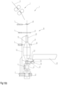
- Fig. 1 shows a schematic representation of a spinning station 10 of a ring spinning machine 1 in a side view, under (a) with an encapsulation in a closed position and under (b) with an encapsulation in an open position.
- the spinning rings 30 of the spinning stations 10 are arranged on a ring bank 3 extending in the longitudinal direction of the ring spinning machine 1.
- the balloon limiters 41 of the spinning stations 10 arranged next to one another are adjustably arranged on a crossbeam 4 extending in the longitudinal direction of the ring spinning machine 1.
- the thread guides 40 of the spinning stations 10 arranged next to one another are adjustably arranged on a crossbeam 5 extending in the longitudinal direction of the ring spinning machine 1.
- the spindles 20 of the spinning stations 10 are arranged on a spindle bank 2 extending in the longitudinal direction of the ring spinning machine 1.
- the spindle 20 of the spinning station 10 shown in the embodiment comprises a whorl 21 and a spindle bearing 22 at a lower end, with which the spindle 20 is rotatably mounted on the spindle bank 2.
- the spindle 20 is driven by a tangential belt 6, which can drive several spinning stations at a time and is pressed against the whorl 21 of the spindle 20. Other drives are also possible.
- Fig. 1(a) further shows an encapsulation 50 of the spinning station device 10 in a closed position.
- the encapsulation 50 is made up of two capsule walls divided in the axial direction in the form of partial or partial shells.
- a rear capsule wall 51 is connected to the spindle bank 2 and is fixed relative to the spindle or fixed but removable.
- a front, operator-side capsule wall 52 can be opened, e.g. by pivoting about a hinge 54 with an axis that lies in a plane perpendicular to the spindle or encapsulation axis.
- the hinge 54 is located on two lateral legs 53 of the rear capsule wall 51, which protrude forwards over the front capsule wall 52.
- a spindle brake 60 is shown schematically, which is arranged here directly below the coil body 13 and above the whorl 21 of the spindle 20.
- the front capsule wall 52 has a brake actuation device 55. This is implemented here in the form of an actuation arm 56 with a ball 57 formed at its free end.
- the front capsule wall 52 has a defined end position in the closed state.
- Means for moving the thread laying in the axial direction of the spindle 20 or the bobbin 13, e.g. in the form of a spinning ring 30 and a ring traveler 31, are provided.
- This can be a slot with a ring holder, for example in the rear capsule wall 51, or for example a magnetic guide of the spinning ring 30.
- Fig. 1(b) shows the spinning station equipment from Fig. 1(a) with the encapsulation 50 in an open position.
- the front capsule wall 52 is pivoted forwards and downwards about the hinge 54, so that the front capsule wall 52 is essentially in a horizontal position. In this way, the coil body 13 is freely accessible for operation.
- the front capsule wall 52 can be easily moved by hand (or by means of a robot) from the closed position to the open position.
- the brake actuating device 55 is attached to the lower end of the front capsule wall 52.
- the brake actuating device 55 - in the embodiment shown, the ball 57 of the brake actuating device 55 - is introduced into the spindle brake and thereby brakes the spindle.
- Other designs of the brake actuating device are also possible.
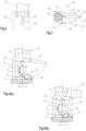
- Fig. 2 shows a front view of the front capsule wall 52 with the brake actuating device 55 designed as actuating arm 56 and ball 57.
- Fig. 3 shows a view of a spindle brake 60 from above.
- the spindle brake 60 is designed as a clamp or pliers and has a first brake lever 61 and a second brake lever 62.
- the two brake levers 61, 62 are connected to one another via a hinge 63.
- the two brake levers 61, 62 each have a brake or clamping jaw which is placed around the spindle 20 of the spinning station device 10.
- the spindle brake 60 is actuated, the clamping jaws are pressed against the spindle 20 and brake it.
- the other end of the two brake levers 61, 62 is designed in such a way that the brake actuation device 55 can be inserted between the two brake levers 61, 62 and pushes these ends of the brake levers 61, 62 apart.
- the clamping jaws are pressed together and brake the spindle.
- the spindle brake 60 can therefore be actuated with a suitable brake actuation device 55, for example in the form of a wedge, a ball 57, a cylinder or another suitable shape, and its braking force can be continuously controlled or regulated.
- a suitable brake actuation device 55 for example in the form of a wedge, a ball 57, a cylinder or another suitable shape, and its braking force can be continuously controlled or regulated.
- the gap shown between the brake levers 61, 62 is wedge-shaped and straight, whereby the wedge shape can have a different angle or any wedge-shaped curved contour in order to be able to adjust the braking effect depending on the path or swivel angle of the actuation.
- One of the brake levers - here the second brake lever 62 - is designed to be spring-loaded, for example by having two parts connected by a spring element 64.
- the spring element 64 can be a spring steel.
- the two brake levers 61, 62 each have stop surfaces 65 for the ball 57 of the brake actuation device 55 at the end facing away from the spindle, which approach the hinge 63 so that a tapering gap is formed between the brake levers 61, 62, into which the ball 57 is inserted.
- the ends of the spindle brake 60 facing away from the spindle are pressed apart and the clamping jaws are pressed against the spindle 20. The braking effect increases in the process.
- the brake levers can have stop surfaces 66 for a constant braking effect, which run essentially parallel to one another when the brake actuation device 55 is inserted.
- the encapsulation 50 can be brought into the fully open position on these, after it has already generated the maximum braking effect in a partially open position. The braking effect is kept constant.
- the brake actuation device 55 is guided to a certain insertion depth on the stop surfaces 65 for an increasing braking effect. It is then guided to the stop surfaces 66 for a constant braking effect until the encapsulation is completely opened.
- the spindle brake can be easily regulated by swiveling the front encapsulation wall 52 out or in. This is particularly advantageous if a spindle decoupling device 70 is also used, as described below under Fig. 4 described.
- a locking position is provided which allows the spindle brake 60 to be kept closed without the brake actuation device 55 having to be held.
- This can be formed in the middle of the gap or at its end. A large number of embodiments are also conceivable for this.
- the brake is designed as a "caliper" that closes when the two actuating levers are pushed apart and does not touch the spindle during normal operation.
- a spring is provided for this purpose, which brings the brake caliper into this position and holds it, although this can also be achieved by a number of other designs of the caliper.
- an elastomer or the design of the caliper as a plastic part that is at least partially elastic can perform the same function.
- the spindle brake can also be designed in such a way that it closes when the brake levers are pressed together.
- the brake levers must then be pressed together by a suitable counterpart of the brake actuation device.
- the wedge shape of the gap of the brake levers can also be integrated into the brake actuation device.
- one of the brake levers or just one brake shoe can be fixed and only one brake lever is actuated.
- Fig. 4 shows a schematic representation of a spindle decoupling device 70 under (a) in a coupled position and under (b) in a decoupled position.
- the front capsule wall 52 has a firmly connected actuating arm 58 for spindle decoupling device 70.
- the actuating arm 58 is for the Spindle decoupling device 70 is shown in dashed lines. This is offset from the spindle 20 in the horizontal longitudinal direction of the ring spinning machine so that it can actuate the spindle decoupling device 70 arranged next to the spindle 20.
- the spindle decoupling device 70 has a carriage 72 that is guided linearly on the spindle bank 2.
- a decoupling roller 71 with a vertical axis of rotation is mounted on the carriage 72 (the axis of rotation is parallel to the spindle axis).
- the carriage 72 is connected to the spindle bank 2 or a guide plate for the carriage 72 via a toggle lever 73. Actuation of the toggle lever 73 leads to a linear displacement of the carriage 72 with the decoupling roller 71.
- the spindle decoupling device 70 is arranged such that the decoupling roller 71 lifts the drive belt 6 from the spindle 20 (or the whorl 21 of the spindle 20) when the knee lever 73 is actuated (cf. Fig. 4(b) ) to prevent the spindle 20 from becoming hot when braked. This is particularly advantageous at higher spindle speeds and greater power transmission.
- the front capsule wall 52 has a rotationally fixed actuating arm or actuating lever 58. If the actuating arm 58 is removed from the toggle lever 73, the drive belt 6 returns the decoupling roller 71, the carriage 72 and the toggle lever 73 to the starting position.
- the process can be supported by a suitable mechanism, e.g. a spring or similar, and the movements can be limited so that the end positions are defined, but the carriage 72 can be removed.
Landscapes
- Engineering & Computer Science (AREA)
- Mechanical Engineering (AREA)
- Textile Engineering (AREA)
- Spinning Or Twisting Of Yarns (AREA)
Claims (17)
- Dispositif de poste de filage (10) pour un métier à filer à anneaux (1), comprenant une broche (20) pour un corps de bobine (13), laquelle est fixée de manière à pouvoir être entraînée en rotation sur un banc à broches (2) etun encapsulage (50) s'étendant dans la direction longitudinale de la broche (20) et entourant le corps de bobine (13), dans lequel l'encapsulage (50) est relié au banc à broches (2), est divisé dans la direction longitudinale et présente une paroi de capsule arrière (51) et une paroi de capsule avant (52), dans lequel la paroi de capsule avant (51) peut être déplacée dans une position ouverte, de sorte que, dans la position ouverte, le corps de bobine (13) du dispositif de poste de filage (10) est accessible pour une manipulation,caractérisé en ce quele dispositif de poste de filage (10) présente en outre un frein de broche (60) qui peut être actionné par l'ouverture de l'encapsulage (50) afin de freiner la broche (20) ou le corps de bobine (13), dans lequel la force de freinage du frein de broche (60) peut être commandée.
- Dispositif de poste de filage selon la revendication 1, caractérisé en ce que la paroi de capsule avant est reliée de manière pivotante au niveau d'une zone inférieure et peut pivoter dans une position de préférence horizontale.
- Dispositif de poste de filage selon la revendication 2, caractérisé en ce que la paroi de capsule arrière (51) est reliée de manière fixe au banc à broches (2) et la paroi de capsule avant (52) est reliée de manière pivotante à la paroi de capsule arrière (51).
- Dispositif de poste de filage selon l'une des revendications précédentes, caractérisé en ce que la paroi de capsule arrière (51) et la paroi de capsule avant (52) sont réaliséees chacune sous forme de demi-coques, lesquelles sont reliées entre elles de préférence dans la zone du banc à broches (2) par une charnière (54).
- Dispositif de poste de filage selon l'une des revendications précédentes, caractérisé en ce que la paroi de capsule avant (52) présente un dispositif d'actionnement de frein (55) qui actionne le frein de broche (60) en déplaçant la paroi de capsule avant (52) dans la position ouverte.
- Dispositif de poste de filage selon l'une des revendications précédentes, caractérisé en ce que la force de freinage du frein de broche (60) peut être commandée en continu.
- Dispositif de poste de filage selon l'une des revendications précédentes, caractérisé en ce qu'un effet de freinage du frein de broche (60) augmente avec un degré d'ouverture croissant de l'encapsulage (50) jusqu'à un effet de freinage maximal.
- Dispositif de poste de filage selon l'une des revendications précédentes, caractérisé en ce que le frein de broche (60) est réalisé sous la forme d'une pince.
- Dispositif de poste de filage selon l'une des revendications précédentes, caractérisé en ce que le dispositif de poste de filage présente une unité d'entraînement à broche unique qui peut être commandée par l'ouverture et/ou la fermeture de l'encapsulage.
- Dispositif de poste de filage selon l'une des revendications 1 à 8, caractérisé en ce que le dispositif de poste de filage (10) présente un dispositif de désaccouplement de broche (70) qui désaccouple un élément d'entraînement (6) du métier à filer à anneaux (1) de la broche (20), par ouverture de l'encapsulage (50).
- Dispositif de poste de filage selon la revendication 10, caractérisé en ce que l'élément d'entraînement (6) est une courroie d'entraînement qui s'appuie contre une poulie (21) de la broche (20) pour faire fonctionner la broche (20).
- Dispositif de poste de filage selon la revendication 11, caractérisé en ce que le dispositif de désaccouplement de broche (70) présente un rouleau de désaccouplement (71) qui est monté de manière mobile en direction de la courroie d'entraînement (6), de sorte que le rouleau de désaccouplement (71) repousse la courroie d'entraînement (6) à l'écart de la poulie (21) lors de l'actionnement du dispositif de désaccouplement de broche (70).
- Dispositif de poste de filage selon l'une des revendications 10 à 12, caractérisé en ce que le frein de broche (60) et le dispositif de désaccouplement de broche (70) sont conçus de telle sorte que l'ouverture de l'encapsulage (50) provoque d'abord l'actionnement du frein de broche jusqu'à l'effet de freinage maximal et par la suite le désaccouplement de l'élément d'entraînement (6) du métier à filer à anneaux (1) de la broche (20).
- Dispositif de poste de filage selon l'une des revendications 10 à 13, caractérisé en ce que le frein de broche (60) et le dispositif de désaccouplement de broche (70) sont conçus de telle sorte que la fermeture de l'encapsulage (50) provoque d'abord l'accouplement de l'élément d'entraînement (6) du métier à filer à anneaux (1) à la broche (20) avant que le frein de broche ne soit ensuite relâché.
- Dispositif de poste de filage selon l'une des revendications 10 à 14, caractérisé en ce que la paroi de capsule avant (52) présente un bras d'actionnement (58) permettant l'actionnement du dispositif de désaccouplement de broche (70).
- Dispositif de poste de filage selon l'une des revendications 12 à 15, caractérisé en ce que le rouleau de désaccouplement (71) est fixé sur un chariot (72) guidé horizontalement, dans lequel le chariot (72) peut être actionné à l'aide d'un levier coudé (73).
- Métier à filer à anneaux comportant une pluralité de dispositifs de postes de filage selon l'une des revendications précédentes.
Applications Claiming Priority (1)
| Application Number | Priority Date | Filing Date | Title |
|---|---|---|---|
| CH70240/21A CH718946A1 (de) | 2021-09-03 | 2021-09-03 | Spinnstelleneinrichtung mit Kapselung. |
Publications (2)
| Publication Number | Publication Date |
|---|---|
| EP4144902A1 EP4144902A1 (fr) | 2023-03-08 |
| EP4144902B1 true EP4144902B1 (fr) | 2024-10-23 |
Family
ID=83004584
Family Applications (1)
| Application Number | Title | Priority Date | Filing Date |
|---|---|---|---|
| EP22191904.6A Active EP4144902B1 (fr) | 2021-09-03 | 2022-08-24 | Dispositif de poste de filage avec emballage |
Country Status (6)
| Country | Link |
|---|---|
| US (1) | US11866855B2 (fr) |
| EP (1) | EP4144902B1 (fr) |
| JP (1) | JP2023037616A (fr) |
| CN (1) | CN115748022A (fr) |
| CH (1) | CH718946A1 (fr) |
| ES (1) | ES3009103T3 (fr) |
Family Cites Families (25)
| Publication number | Priority date | Publication date | Assignee | Title |
|---|---|---|---|---|
| DE1510657B1 (de) | 1964-12-03 | 1970-04-02 | Hamel Gmbh | Ringspindelanordnung fuer Spinn- und Zwirnmaschinen |
| DE1685679A1 (de) | 1968-01-23 | 1971-10-21 | Hamel Gmbh | Ringspinn- oder -zwirnmaschine |
| DE1750203A1 (de) * | 1968-04-06 | 1971-01-07 | Weller Maschf Heinz | Innenbackenbremse,insbesondere zum Stillsetzen von Doppeldraht-Zwirnspindeln |
| DE1760270A1 (de) * | 1968-04-26 | 1971-03-18 | Weller Maschf Heinz | Verkleidung fuer Zwirnspindeln |
| DE2238610B2 (de) * | 1972-08-05 | 1977-01-20 | SKF KugeUagerfabriken GmbH, 8720 Schweinfurt | Offen-end-spinnvorrichtung |
| US3823540A (en) * | 1972-09-13 | 1974-07-16 | Rieter Ag Maschf | Brake for spinning and twisting spindles |
| JPS50141A (fr) * | 1973-05-11 | 1975-01-06 | ||
| US3973381A (en) * | 1974-08-08 | 1976-08-10 | Murata Kikai Kabushiki Kaisha | Cover for yarn twisting machine |
| DE3123887A1 (de) * | 1981-06-16 | 1983-01-05 | Fritz 7347 Bad Überkingen Stahlecker | Umwindegarnspinnmaschine |
| DE3929097C2 (de) | 1989-09-01 | 1997-07-03 | Rieter Ag Maschf | Flugabsaugvorrichtung für eine Textilmaschine, insbesondere Ringspinnmaschine |
| DE19705872A1 (de) * | 1996-06-25 | 1998-01-02 | Novibra Gmbh | Ringspinn- oder Ringzwirnmaschine |
| CZ286824B6 (cs) * | 1998-05-20 | 2000-07-12 | Výzkumný Ústav Bavlnářský A. S. | Zařízení pro vřetenové předení nebo skaní |
| DE19848752A1 (de) | 1998-10-22 | 2000-04-27 | Rieter Ag Maschf | Spinnmaschine mit rohrförmigem Ballonbegrenzer |
| ES2187227B1 (es) * | 1999-12-27 | 2004-10-16 | Galan Textile Machinery, S.L. | Maquina de hilar retorcedera-reunidora de anillos, de modulos unitarios de produccion autonomos e independientes. |
| CH697668B1 (de) * | 2004-09-23 | 2009-01-15 | Rieter Ag Maschf | Spindel mit Abschirmelement. |
| CZ2005238A3 (cs) * | 2005-04-18 | 2006-12-13 | Maschinenfabrik Rieter Ag | Zarízení pro smyckové predení nebo skaní |
| DE102005045791A1 (de) * | 2005-09-24 | 2007-03-29 | Saurer Gmbh & Co. Kg | Abdeckung zum Schutz für eine Spindelanordnung |
| JP5746069B2 (ja) | 2012-02-22 | 2015-07-08 | 株式会社豊田自動織機 | リングを有する紡機 |
| CH706759A1 (de) | 2012-07-25 | 2014-01-31 | Rieter Ag Maschf | Abschirmelement für eine Spindel |
| CH714315A1 (de) | 2017-11-10 | 2019-05-15 | Rieter Ag Maschf | Ringspinnmaschine mit beweglich gelagerter Spindelbank. |
| CZ2018645A3 (cs) | 2018-11-23 | 2020-06-03 | Rieter Cz S.R.O. | Vřeteno prstencového dopřádacího stroje |
| CN209957949U (zh) | 2019-02-21 | 2020-01-17 | 江阴华方佳友智能设备有限公司 | 一种锭子抬高安装的细纱机 |
| CH715908A1 (de) | 2019-03-07 | 2020-09-15 | Rieter Ag Maschf | Verfahren zur Herstellung von Garn mit einer Ringspinnmaschine und Ringspinnmaschine. |
| CN210194054U (zh) | 2019-04-10 | 2020-03-27 | 北京中科远恒科技有限公司 | 环锭纺纱机 |
| DE102019116278A1 (de) * | 2019-06-14 | 2020-12-17 | Saurer Intelligent Technology AG | Textilmaschine |
-
2021
- 2021-09-03 CH CH70240/21A patent/CH718946A1/de unknown
-
2022
- 2022-08-24 EP EP22191904.6A patent/EP4144902B1/fr active Active
- 2022-08-24 ES ES22191904T patent/ES3009103T3/es active Active
- 2022-09-01 US US17/823,977 patent/US11866855B2/en active Active
- 2022-09-01 CN CN202211065732.XA patent/CN115748022A/zh active Pending
- 2022-09-02 JP JP2022140098A patent/JP2023037616A/ja active Pending
Also Published As
| Publication number | Publication date |
|---|---|
| CN115748022A (zh) | 2023-03-07 |
| ES3009103T3 (en) | 2025-03-26 |
| JP2023037616A (ja) | 2023-03-15 |
| CH718946A1 (de) | 2023-03-15 |
| EP4144902A1 (fr) | 2023-03-08 |
| US11866855B2 (en) | 2024-01-09 |
| US20230228006A1 (en) | 2023-07-20 |
Similar Documents
| Publication | Publication Date | Title |
|---|---|---|
| DE3400327C2 (fr) | ||
| DE10139072B4 (de) | Serviceaggregat zum Wiederanspinnen von Arbeitsstellen einer Offenend-Spinnmaschine | |
| WO2020178779A1 (fr) | Procédé de fabrication de fil au moyen d'un continu à filer à anneaux et continu à filer à anneaux | |
| EP2256238B1 (fr) | Dispositif de pince-fil pour une broche d'un métier à tisser ou d'une retordeuse | |
| DE2753349A1 (de) | Verfahren und vorrichtung zum anspinnen eines umwindegarnes | |
| DE1510800B2 (de) | Vorrichtung zum selbsttätigen Spulenwechsel an Doppeldrahtzwirnmaschinen | |
| EP4144902B1 (fr) | Dispositif de poste de filage avec emballage | |
| DE4431830C1 (de) | Verfahren zum Anspinnen eines Fadens in einer Vorrichtung zur Herstellung eines Zwirns in einem integrierten Spinn-Zwirnprozeß sowie Vorrichtung zur Durchführung des Verfahrens | |
| EP2784194A1 (fr) | Dispositif de guidage de fil pour une machine textile, notamment pour un métier à filer continu | |
| DE19705872A1 (de) | Ringspinn- oder Ringzwirnmaschine | |
| EP1244831B1 (fr) | Procede de filature a fibres liberees, au moyen d'un rotor | |
| DE3516120A1 (de) | Verfahren zum automatischen anspinnen und automatische anspinnvorrichtung | |
| DE3416886A1 (de) | Oe-friktionsspinnmaschine | |
| DE2653697C2 (de) | Vorrichtung zum Ringspinnen oder Ringzwirnen | |
| EP2267200B1 (fr) | Procédé de fonctionnement d'un poste de travail et poste de travail d'un métier à tisser à rotor à extrémité ouverte | |
| DE102020118327A1 (de) | Verfahren und Vorrichtung zur Falschdrahteinleitung sowie Spinnmaschine | |
| DE4010018C2 (de) | Spindel zum Herstellen eines Fadens | |
| DE102005023517A1 (de) | Offenend-Spinnvorrichtung | |
| DE19837746B4 (de) | Vorrichtung zum Aufwickeln eines synthetischen Endlosfadens auf einen Kops | |
| DE1069044B (de) | Anzwirnvorrichtung für eine Streckzwirnmaschine | |
| DE102022100422A1 (de) | Verfahren und Vorrichtung zur Falschdrahteinleitung sowie Spinnmaschine | |
| DE102022134610A1 (de) | Abspulvorrichtung, Verseilmaschine sowie Verwendung einer Abspulvorrichtung | |
| EP0353575A1 (fr) | Dispositif d'arrêt pour un ruban de fibres | |
| CH697093A5 (de) | Trichterspinnvorrichtung mit Trichter und Abschirmelement. | |
| EP1763598A1 (fr) | Dispositif de filage ou de retordage avec bouclage |
Legal Events
| Date | Code | Title | Description |
|---|---|---|---|
| PUAI | Public reference made under article 153(3) epc to a published international application that has entered the european phase |
Free format text: ORIGINAL CODE: 0009012 |
|
| STAA | Information on the status of an ep patent application or granted ep patent |
Free format text: STATUS: THE APPLICATION HAS BEEN PUBLISHED |
|
| AK | Designated contracting states |
Kind code of ref document: A1 Designated state(s): AL AT BE BG CH CY CZ DE DK EE ES FI FR GB GR HR HU IE IS IT LI LT LU LV MC MK MT NL NO PL PT RO RS SE SI SK SM TR |
|
| STAA | Information on the status of an ep patent application or granted ep patent |
Free format text: STATUS: REQUEST FOR EXAMINATION WAS MADE |
|
| 17P | Request for examination filed |
Effective date: 20230908 |
|
| RBV | Designated contracting states (corrected) |
Designated state(s): AL AT BE BG CH CY CZ DE DK EE ES FI FR GB GR HR HU IE IS IT LI LT LU LV MC MK MT NL NO PL PT RO RS SE SI SK SM TR |
|
| GRAP | Despatch of communication of intention to grant a patent |
Free format text: ORIGINAL CODE: EPIDOSNIGR1 |
|
| STAA | Information on the status of an ep patent application or granted ep patent |
Free format text: STATUS: GRANT OF PATENT IS INTENDED |
|
| INTG | Intention to grant announced |
Effective date: 20240613 |
|
| GRAS | Grant fee paid |
Free format text: ORIGINAL CODE: EPIDOSNIGR3 |
|
| GRAA | (expected) grant |
Free format text: ORIGINAL CODE: 0009210 |
|
| STAA | Information on the status of an ep patent application or granted ep patent |
Free format text: STATUS: THE PATENT HAS BEEN GRANTED |
|
| AK | Designated contracting states |
Kind code of ref document: B1 Designated state(s): AL AT BE BG CH CY CZ DE DK EE ES FI FR GB GR HR HU IE IS IT LI LT LU LV MC MK MT NL NO PL PT RO RS SE SI SK SM TR |
|
| REG | Reference to a national code |
Ref country code: GB Ref legal event code: FG4D Free format text: NOT ENGLISH |
|
| REG | Reference to a national code |
Ref country code: CH Ref legal event code: EP |
|
| REG | Reference to a national code |
Ref country code: DE Ref legal event code: R096 Ref document number: 502022001956 Country of ref document: DE |
|
| REG | Reference to a national code |
Ref country code: IE Ref legal event code: FG4D Free format text: LANGUAGE OF EP DOCUMENT: GERMAN |
|
| REG | Reference to a national code |
Ref country code: LT Ref legal event code: MG9D |
|
| REG | Reference to a national code |
Ref country code: NL Ref legal event code: MP Effective date: 20241023 |
|
| PG25 | Lapsed in a contracting state [announced via postgrant information from national office to epo] |
Ref country code: NL Free format text: LAPSE BECAUSE OF FAILURE TO SUBMIT A TRANSLATION OF THE DESCRIPTION OR TO PAY THE FEE WITHIN THE PRESCRIBED TIME-LIMIT Effective date: 20241023 |
|
| REG | Reference to a national code |
Ref country code: ES Ref legal event code: FG2A Ref document number: 3009103 Country of ref document: ES Kind code of ref document: T3 Effective date: 20250326 |
|
| PG25 | Lapsed in a contracting state [announced via postgrant information from national office to epo] |
Ref country code: NL Free format text: LAPSE BECAUSE OF FAILURE TO SUBMIT A TRANSLATION OF THE DESCRIPTION OR TO PAY THE FEE WITHIN THE PRESCRIBED TIME-LIMIT Effective date: 20241023 |
|
| PG25 | Lapsed in a contracting state [announced via postgrant information from national office to epo] |
Ref country code: PT Free format text: LAPSE BECAUSE OF FAILURE TO SUBMIT A TRANSLATION OF THE DESCRIPTION OR TO PAY THE FEE WITHIN THE PRESCRIBED TIME-LIMIT Effective date: 20250224 Ref country code: HR Free format text: LAPSE BECAUSE OF FAILURE TO SUBMIT A TRANSLATION OF THE DESCRIPTION OR TO PAY THE FEE WITHIN THE PRESCRIBED TIME-LIMIT Effective date: 20241023 Ref country code: IS Free format text: LAPSE BECAUSE OF FAILURE TO SUBMIT A TRANSLATION OF THE DESCRIPTION OR TO PAY THE FEE WITHIN THE PRESCRIBED TIME-LIMIT Effective date: 20250223 |
|
| PG25 | Lapsed in a contracting state [announced via postgrant information from national office to epo] |
Ref country code: FI Free format text: LAPSE BECAUSE OF FAILURE TO SUBMIT A TRANSLATION OF THE DESCRIPTION OR TO PAY THE FEE WITHIN THE PRESCRIBED TIME-LIMIT Effective date: 20241023 |
|
| PG25 | Lapsed in a contracting state [announced via postgrant information from national office to epo] |
Ref country code: BG Free format text: LAPSE BECAUSE OF FAILURE TO SUBMIT A TRANSLATION OF THE DESCRIPTION OR TO PAY THE FEE WITHIN THE PRESCRIBED TIME-LIMIT Effective date: 20241023 |
|
| PG25 | Lapsed in a contracting state [announced via postgrant information from national office to epo] |
Ref country code: NO Free format text: LAPSE BECAUSE OF FAILURE TO SUBMIT A TRANSLATION OF THE DESCRIPTION OR TO PAY THE FEE WITHIN THE PRESCRIBED TIME-LIMIT Effective date: 20250123 |
|
| PG25 | Lapsed in a contracting state [announced via postgrant information from national office to epo] |
Ref country code: LV Free format text: LAPSE BECAUSE OF FAILURE TO SUBMIT A TRANSLATION OF THE DESCRIPTION OR TO PAY THE FEE WITHIN THE PRESCRIBED TIME-LIMIT Effective date: 20241023 Ref country code: GR Free format text: LAPSE BECAUSE OF FAILURE TO SUBMIT A TRANSLATION OF THE DESCRIPTION OR TO PAY THE FEE WITHIN THE PRESCRIBED TIME-LIMIT Effective date: 20250124 |
|
| PG25 | Lapsed in a contracting state [announced via postgrant information from national office to epo] |
Ref country code: PL Free format text: LAPSE BECAUSE OF FAILURE TO SUBMIT A TRANSLATION OF THE DESCRIPTION OR TO PAY THE FEE WITHIN THE PRESCRIBED TIME-LIMIT Effective date: 20241023 |
|
| PG25 | Lapsed in a contracting state [announced via postgrant information from national office to epo] |
Ref country code: RS Free format text: LAPSE BECAUSE OF FAILURE TO SUBMIT A TRANSLATION OF THE DESCRIPTION OR TO PAY THE FEE WITHIN THE PRESCRIBED TIME-LIMIT Effective date: 20250123 |
|
| PG25 | Lapsed in a contracting state [announced via postgrant information from national office to epo] |
Ref country code: SM Free format text: LAPSE BECAUSE OF FAILURE TO SUBMIT A TRANSLATION OF THE DESCRIPTION OR TO PAY THE FEE WITHIN THE PRESCRIBED TIME-LIMIT Effective date: 20241023 |
|
| PG25 | Lapsed in a contracting state [announced via postgrant information from national office to epo] |
Ref country code: DK Free format text: LAPSE BECAUSE OF FAILURE TO SUBMIT A TRANSLATION OF THE DESCRIPTION OR TO PAY THE FEE WITHIN THE PRESCRIBED TIME-LIMIT Effective date: 20241023 |
|
| PG25 | Lapsed in a contracting state [announced via postgrant information from national office to epo] |
Ref country code: EE Free format text: LAPSE BECAUSE OF FAILURE TO SUBMIT A TRANSLATION OF THE DESCRIPTION OR TO PAY THE FEE WITHIN THE PRESCRIBED TIME-LIMIT Effective date: 20241023 |
|
| PG25 | Lapsed in a contracting state [announced via postgrant information from national office to epo] |
Ref country code: RO Free format text: LAPSE BECAUSE OF FAILURE TO SUBMIT A TRANSLATION OF THE DESCRIPTION OR TO PAY THE FEE WITHIN THE PRESCRIBED TIME-LIMIT Effective date: 20241023 |
|
| REG | Reference to a national code |
Ref country code: DE Ref legal event code: R097 Ref document number: 502022001956 Country of ref document: DE |
|
| PG25 | Lapsed in a contracting state [announced via postgrant information from national office to epo] |
Ref country code: SK Free format text: LAPSE BECAUSE OF FAILURE TO SUBMIT A TRANSLATION OF THE DESCRIPTION OR TO PAY THE FEE WITHIN THE PRESCRIBED TIME-LIMIT Effective date: 20241023 |
|
| PLBE | No opposition filed within time limit |
Free format text: ORIGINAL CODE: 0009261 |
|
| STAA | Information on the status of an ep patent application or granted ep patent |
Free format text: STATUS: NO OPPOSITION FILED WITHIN TIME LIMIT |
|
| PG25 | Lapsed in a contracting state [announced via postgrant information from national office to epo] |
Ref country code: SE Free format text: LAPSE BECAUSE OF FAILURE TO SUBMIT A TRANSLATION OF THE DESCRIPTION OR TO PAY THE FEE WITHIN THE PRESCRIBED TIME-LIMIT Effective date: 20241023 |
|
| 26N | No opposition filed |
Effective date: 20250724 |
|
| PGFP | Annual fee paid to national office [announced via postgrant information from national office to epo] |
Ref country code: ES Payment date: 20250917 Year of fee payment: 4 |
|
| PGFP | Annual fee paid to national office [announced via postgrant information from national office to epo] |
Ref country code: DE Payment date: 20250819 Year of fee payment: 4 |
|
| PGFP | Annual fee paid to national office [announced via postgrant information from national office to epo] |
Ref country code: TR Payment date: 20250814 Year of fee payment: 4 Ref country code: IT Payment date: 20250901 Year of fee payment: 4 |
|
| PGFP | Annual fee paid to national office [announced via postgrant information from national office to epo] |
Ref country code: AT Payment date: 20251020 Year of fee payment: 4 |
|
| PGFP | Annual fee paid to national office [announced via postgrant information from national office to epo] |
Ref country code: CH Payment date: 20250901 Year of fee payment: 4 |
|
| PGFP | Annual fee paid to national office [announced via postgrant information from national office to epo] |
Ref country code: CZ Payment date: 20250808 Year of fee payment: 4 |
|
| PG25 | Lapsed in a contracting state [announced via postgrant information from national office to epo] |
Ref country code: MC Free format text: LAPSE BECAUSE OF FAILURE TO SUBMIT A TRANSLATION OF THE DESCRIPTION OR TO PAY THE FEE WITHIN THE PRESCRIBED TIME-LIMIT Effective date: 20241023 |
|
| PG25 | Lapsed in a contracting state [announced via postgrant information from national office to epo] |
Ref country code: LU Free format text: LAPSE BECAUSE OF NON-PAYMENT OF DUE FEES Effective date: 20250824 |