EP4144919B1 - Procédé et engin de construction pour le compactage du sol - Google Patents
Procédé et engin de construction pour le compactage du sol Download PDFInfo
- Publication number
- EP4144919B1 EP4144919B1 EP22204100.6A EP22204100A EP4144919B1 EP 4144919 B1 EP4144919 B1 EP 4144919B1 EP 22204100 A EP22204100 A EP 22204100A EP 4144919 B1 EP4144919 B1 EP 4144919B1
- Authority
- EP
- European Patent Office
- Prior art keywords
- support cable
- winch
- cable
- winch drum
- compacting element
- Prior art date
- Legal status (The legal status is an assumption and is not a legal conclusion. Google has not performed a legal analysis and makes no representation as to the accuracy of the status listed.)
- Active
Links
Images
Classifications
-
- B—PERFORMING OPERATIONS; TRANSPORTING
- B66—HOISTING; LIFTING; HAULING
- B66C—CRANES; LOAD-ENGAGING ELEMENTS OR DEVICES FOR CRANES, CAPSTANS, WINCHES, OR TACKLES
- B66C13/00—Other constructional features or details
- B66C13/18—Control systems or devices
- B66C13/46—Position indicators for suspended loads or for crane elements
-
- B—PERFORMING OPERATIONS; TRANSPORTING
- B66—HOISTING; LIFTING; HAULING
- B66D—CAPSTANS; WINCHES; TACKLES, e.g. PULLEY BLOCKS; HOISTS
- B66D1/00—Rope, cable, or chain winding mechanisms; Capstans
- B66D1/28—Other constructional details
- B66D1/40—Control devices
- B66D1/48—Control devices automatic
- B66D1/485—Control devices automatic electrical
-
- B—PERFORMING OPERATIONS; TRANSPORTING
- B66—HOISTING; LIFTING; HAULING
- B66D—CAPSTANS; WINCHES; TACKLES, e.g. PULLEY BLOCKS; HOISTS
- B66D1/00—Rope, cable, or chain winding mechanisms; Capstans
- B66D1/28—Other constructional details
- B66D1/40—Control devices
- B66D1/48—Control devices automatic
- B66D1/50—Control devices automatic for maintaining predetermined rope, cable, or chain tension, e.g. in ropes or cables for towing craft, in chains for anchors; Warping or mooring winch-cable tension control
- B66D1/505—Control devices automatic for maintaining predetermined rope, cable, or chain tension, e.g. in ropes or cables for towing craft, in chains for anchors; Warping or mooring winch-cable tension control electrical
-
- E—FIXED CONSTRUCTIONS
- E02—HYDRAULIC ENGINEERING; FOUNDATIONS; SOIL SHIFTING
- E02D—FOUNDATIONS; EXCAVATIONS; EMBANKMENTS; UNDERGROUND OR UNDERWATER STRUCTURES
- E02D3/00—Improving or preserving soil or rock, e.g. preserving permafrost soil
- E02D3/02—Improving by compacting
-
- E—FIXED CONSTRUCTIONS
- E02—HYDRAULIC ENGINEERING; FOUNDATIONS; SOIL SHIFTING
- E02D—FOUNDATIONS; EXCAVATIONS; EMBANKMENTS; UNDERGROUND OR UNDERWATER STRUCTURES
- E02D3/00—Improving or preserving soil or rock, e.g. preserving permafrost soil
- E02D3/02—Improving by compacting
- E02D3/046—Improving by compacting by tamping or vibrating, e.g. with auxiliary watering of the soil
Definitions
- the invention relates to a method for soil compaction with a construction machine, wherein a support cable is guided along a mast, the support cable is wound up and unwound by means of a rotatably mounted winch drum of a cable winch, the winch drum is driven in rotation by means of a winch drive and a compaction element is arranged on the support cable, which is moved vertically by the support cable, wherein the support cable is unwound from the winch drum of the cable winch and the compaction element is lowered from a position above a ground surface on the support cable to the ground surface, wherein the compaction element strikes the ground surface and compacts the soil, according to the preamble of claim 1.
- the invention further relates to a construction machine for soil compaction with a mast, a support cable which is guided along the mast, a cable winch with a rotatably mounted winch drum to which the support cable is attached for winding and unwinding, a winch drive for rotating the winch drum, a compaction element which is attached to the support cable for vertical movement, and a control unit by which the cable winch can be operated to unwind the support cable from the winch drum, wherein the compaction element on the support cable is lowered to a ground surface and the compaction element strikes the ground surface to compact the soil, according to the preamble of claim 11.
- a generic construction machine comes from the EP 3 708 528 A1 out.
- Such a disordered rope winding on the winch drum can lead to damage to the winch drum and in particular to increased wear of the suspension rope. This can not only significantly shorten the service life of the suspension rope, but can also affect the maximum load capacity of the suspension rope overall.
- the EP 3 708 528 A1 A rope pressure device with at least one pressure element must be provided in the area of the winch drum. This can reliably prevent the rope vibration of the support rope from spreading to the rope area wound on the winch drum.
- the rope pressure device means additional construction work and requires a corresponding amount of space on the construction machine. The rope pressure device also requires maintenance at certain intervals.
- the invention is based on the object of specifying a method and a construction machine for soil compaction, with which the negative effects of a rope vibration of the support rope on the rope winding on the winch drum can be counteracted particularly efficiently.
- the object is achieved by initially briefly tensioning the support cable in the area of the winch after the compaction element has hit the ground and then automatically unwinding the support cable from the winch drum by a certain amount by the control unit before the compaction element is lifted from the ground again.
- the support cable is wound up again immediately afterwards.
- this method it is intended to counteract incorrect winding of the support cable on the winch drum by first briefly tensioning the support cable in the area of the winch without lifting the compaction element from the ground. Then, before lifting the compaction element from the ground, the support cable thus tensioned is automatically unwound and relaxed by the control unit by a certain amount, whereby any offset of the winding on the winch drum that may have occurred is removed again by unwinding.
- the support cable can then be automatically wound up again by the control unit and the compaction element can be lifted off the ground until the compaction element reaches the desired starting position above the ground for another compaction process.
- This method according to the invention ensures that even if an offset occurs on the cable winding, this is automatically and reliably eliminated by the control unit and thus no permanent incorrect winding of the support cable can form on the winch drum. This also reliably counteracts cable wear.
- the amount or the extent of unwinding the support cable before the compaction element is raised again by winding up the support cable can be adjusted in any suitable manner. According to a further development of the invention, it is particularly advantageous that the support cable is unwound until the support cable is correctly wound on the winch drum. This This ensures clean winding and thus low wear of the suspension cable in the long term.
- the winding can be observed directly by a machine operator from an operator's cabin.
- a clean cable winding can also be ensured with any arrangement of the winch drum according to a further development of the invention by detecting a winding of the support cable on the winch drum using a sensor unit, in particular a camera unit or a radar unit or another suitable sensor.
- the image from the camera unit can be displayed to a machine operator in the machine cabin. Detection can be optical, contactless via energy waves, tactile, electronic, magnetic, by reed contact or in another suitable manner.
- the sensor unit can be connected to the control unit, which uses signals or data recorded by the sensor unit to determine whether the winch drum is correctly wound.
- the signal or data can in particular be an image.
- the recorded sensor signal for the rope winding is evaluated electronically, for example using image processing software.
- the machine operator or the control unit can individually set an amount or a measure of the unwinding of the supporting rope until the rope is correctly wound on the winch drum.
- the amount of unwinding can be specified as a rotation angle measurement for the winch drum or a length measurement for the supporting rope or a time period for controlling the winch drive (at a defined speed).
- the amount of unwinding of the support cable is automatically set by the control unit or by a machine operator before a new lifting process of the compaction element.
- the amount can be constant or variable.
- a further development of the method according to the invention for soil compaction is characterized in that the winch drum is decoupled from the winch drive via a coupling device when the support cable is unwound, that the winch drive is driven in a direction of rotation to wind up the support cable before the compaction element hits the ground surface, and that after the compaction element hits the ground surface, the coupling device couples the winch drum to the winch drive which is already rotating.
- the method is based on the knowledge that insufficient tension of the support cable in the area of the winch caused by a cable vibration can lead to cable windings on the winch drum jumping out of their intended position.
- the winch drive is decoupled from the winch drum via a coupling device when the support cable is unwound in a period of time before the compaction element hits the ground.
- the movement of the winch drum is thus independent of the movement of the winch drive. This independence can be used to operate the winch drive early in a direction of rotation that is required for winding up the support cable.
- the coupling device can be used to reconnect or couple the winch drum to the winch drive, particularly immediately after the compaction element hits the ground, whereby the torque of the winch drive on the drive shaft can have a direct effect on the winch drum and a resulting abruptly starting rotational movement of the winch drum in the direction of winding up the support cable leads to very rapid cable tension in the area of the winch.
- a winding force can be applied to the support cable via the winch drum immediately after or when the compaction element hits the ground, so that it is immediately tensioned again in the area of the winch. Due to this immediate cable tension, the formation of slack in the area of the winch and the associated jumping of cable windings on the winch drum from their intended position is prevented. This significantly reduces the risk of unwanted misalignment of rope windings on the winch drum.
- the support cable can in principle be connected directly to the compaction element.
- a chain and/or a steel cable suspension is arranged as a buffer between the support cable and the compaction element. This can prevent the support cable from being compressed by standing on the compaction element when braking.
- at least one additional weight for example in the form of a steel crossbeam, can optionally be arranged between the support cable and the steel cable suspension.
- the method for soil compaction can be carried out manually by a machine operator.
- the method is carried out automatically by means of a control unit.
- the control unit can in particular be connected to the winch drive and the coupling device and actuate them accordingly.
- the control unit can also be connected to one or more sensors by which a position of the compaction element and/or the cable tension is detected.
- the coupling device can be designed as a lockable freewheel clutch, whereby locking or unlocking can be effected by the control unit.
- the coupling device can basically be designed in any suitable way. According to a further development of the invention, it is particularly expedient for the coupling device to comprise a free-fall brake, whereby the support cable is unwound in a free fall of the compaction element. With a free-fall brake, after the brake is opened, the winch drum can be driven with little friction solely by the weight of the compaction element attached to the support cable, whereby the compaction element can hit the ground surface in free fall, so to speak. During this free fall, a certain minimum tensile stress is present on the support cable.
- a free-fall or free-running mode can be ended electronically or by corresponding mechanical components when the cable hits the ground surface and the tension in the cable is reduced as a result, whereby coupling, i.e. the creation of a torque-transmitting connection, between the winch drive and the winch drum.
- the free-fall brake which can be part of the coupling device or form the entire device, can be connected to the control unit, which can basically comprise an electronic computer unit.
- the coupling device can be activated at any time.
- a preferred method variant of the invention consists in the coupling device carrying out a coupling when the compaction element reaches the ground surface. This ensures that, on the one hand, the compaction element achieves the freest possible falling movement and, on the other hand, immediately after impact with the ground, torque is transmitted from the winch drive to the winch drum to generate the desired cable tension of the support cable in the area of the winch.
- any torque can be set for any period of time on the winch drive.
- the winch drive generates a tightening torque when coupling, which tightens the support cable in the area of the winch.
- the tightening torque can preferably be designed so that it leads to a desired cable tension, but the compaction element is not lifted from the ground. A second, higher torque can then be set for lifting.
- control unit is provided which is designed to carry out one of the previously described methods for soil compaction.
- the control unit can in particular be an electronic control unit and in particular can be integrated into an existing control unit of a construction machine.
- the winch drum can also be arranged directly on the mast and in particular in an upper area of the mast. According to a further development of the invention, it is particularly expedient for the support cable to be attached to the upper end of the mast.
- the winch drum and the winch drive can thus be provided directly or close to a carrier device, so that the construction machine as a whole has the lowest possible center of gravity.
- the carrier device can in particular have an undercarriage with an upper carriage mounted rotatably thereon.
- the undercarriage can in particular comprise a chassis, in particular a crawler chassis.
- At least one sensor unit in particular a camera unit, a radar unit or an ultrasound or another suitable sensor, is arranged in the region of the winch drum for detecting a winding of the support cable on the winch drum.
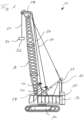
- a construction machine 10 designed as a crawler crane from Fig.1 has a mobile carrier device 12.
- the carrier device 12 comprises a crawler chassis 14 on which an upper carriage 15 is rotatably mounted.
- a mast 16 which is also referred to as a boom arm, is mounted on the upper carriage 15 so as to be pivotable about a horizontal pivot axis.
- a support beam 26, a support beam 28 and an adjusting cable mechanism 27 are provided on the upper carriage 15 in a basically known manner.
- At least one support cable 20 is guided from the upper carriage 15 via a mast head 18 of the mast 16, on which a compaction element 30 is suspended, which in the illustrated embodiment is designed as an impact weight 32 for soil compaction.
- the support cable 20 is adjustably driven via a double winch arrangement in the upper carriage 15, as is basically known from the prior art.
- a cable pressure device 40 can be arranged on each of the two sections of the support cable 20, one of which is attached to the support beam 26, also called an A-frame, and the other to the mast 16.
- the ends of the support cable 20 are each attached to a cable winch in the upper carriage 15, so that a double cable winch arrangement is provided for fast lifting processes.
- a control unit can be provided on the upper carriage 15, in particular in a cabin.
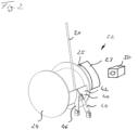
- a possible arrangement of a cable winch 22 for the construction machine 10 according to the invention is shown.
- the cable winch 22 has a winch drum 24 for winding and unwinding the support cable 20.
- the winch drum 24 can be driven in rotation in basically both directions of rotation via a winch drive 23 (only partially shown) via an intermediate coupling device 25.
- the coupling device 25 can be designed as a lockable freewheel clutch or a so-called free fall brake, whereby the support cable 20 is unwound in free fall, so to speak, solely via the weight of the compaction element 30.
- the coupling device 25 can immediately establish a rotationally fixed connection between the winch drive 23 and the winch drum 24.
- the winch drive 23 is driven in a winding direction, clockwise in the illustrated embodiment, preferably via the control unit before reconnection by the coupling device 25.
- a tightening torque of the winch drive 23 is applied to the winch drum 24.
- a desired tension of the support cable 20 can be achieved in the area of the cable winch 22.
- a clean winding of the support cable 20 on the winch drum 24 can be monitored by a camera unit 50 as a sensor unit.
- a radar unit, ultrasound or another suitable sensor such as an optical sensor, a magnetic sensor or a reed contact can also be used.
- the support cable 20 can be unwound by a machine operator or preferably automatically via the control unit if an undesirable offset of the support cable 20 on the winch drum 24 occurs before the compaction element 30 is raised from the ground again.
- a clean winding can be carried out via the winch drum 24, followed by a lifting of the compaction element 30 from the ground. This allows a clean winding of the support rope 20 on the winch drum 24.
- a further, generally known, rope pressure device 40 with a plate-shaped pressure element 42 can be provided on the winch drum 24.
- the pressure element 42 is movably mounted by means of a base support 46 and can be pressed onto the rope winding on the winch drum 24 by means of a pressure cylinder 48 to additionally prevent rope misalignment.
Landscapes
- Engineering & Computer Science (AREA)
- Structural Engineering (AREA)
- Life Sciences & Earth Sciences (AREA)
- Mechanical Engineering (AREA)
- General Life Sciences & Earth Sciences (AREA)
- Soil Sciences (AREA)
- Environmental & Geological Engineering (AREA)
- Mining & Mineral Resources (AREA)
- Paleontology (AREA)
- Civil Engineering (AREA)
- General Engineering & Computer Science (AREA)
- Agronomy & Crop Science (AREA)
- Automation & Control Theory (AREA)
- Road Paving Machines (AREA)
Claims (13)
- Procédé de compactage de sol avec un engin de construction (10), dans lequel- un câble de support (20) est guidé le long d'un mât (16),- le câble de support (20) est enroulé et déroulé au moyen d'un tambour de treuil (24) monté tournant qui fait partie d'un treuil (22),- le tambour de treuil (24) est entraîné en rotation au moyen d'un entraînement de treuil (23), et- un élément de compactage (30) est disposé sur le câble de support (20), lequel est déplacé verticalement par le câble de support (20), le câble de support (20) étant déroulé du tambour de treuil (24) du treuil (22) et l'élément de compactage (30) étant abaissé, sur le câble de support (20), depuis une position au-dessus d'une surface au sol jusqu'à la surface au sol avec une percussion de l'élément de compactage (30) contre la surface au sol, le sol étant ainsi compacté,
caractérisé- en ce que le câble de support (20) est tendu d'abord au niveau de la zone du treuil (22) après que l'élément de compactage (30) a percuté le sol puis le câble de support (20) est déroulé automatiquement par l'unité de commande du tambour de treuil (24) d'une certaine longueur pouvant être réglée de préférence par le conducteur d'engin avant que l'élément de compactage (30) ne soit à nouveau soulevé du sol. - Procédé selon la revendication 1,
caractérisé en ce qu'un déroulement du câble de support (20) est effectué jusqu'à ce qu'un enroulement correct du câble de support (20) sur le tambour de treuil (24) soit réalisé. - Procédé selon l'une quelconque des revendications 1 ou 2,
caractérisé en ce que la longueur de déroulement du câble de support (20) est réglée par un opérateur d'engin ou automatiquement par une unité de commande avant une nouvelle opération de levage de l'élément de compactage (30). - Procédé selon l'une quelconque des revendications 1 à 3,
caractérisé en ce qu'un enroulement du câble de support (20) sur le tambour de treuil (24) est détecté au moyen d'une unité de capteur, en particulier d'une unité de caméra (50) ou d'une unité radar. - Procédé selon la revendication 4,
caractérisé en ce que l'unité de capteur est reliée à une unité de commande qui détermine, à l'aide d'un signal détecté par l'unité de capteur, si un enroulement correct est réalisé sur le tambour de treuil (24). - Procédé selon l'une quelconque des revendications 1 à 5,
caractérisé en ce que le procédé est automatiquement mis en oeuvre au moyen d'une unité de commande. - Procédé selon l'une quelconque des revendications 1 à 6,
caractérisé par le fait :- que le tambour de treuil (24) est découplé de l'entraînement de treuil (23) lors du déroulement du câble de support (20) par l'intermédiaire d'un dispositif de couplage (25),- que, avant encore que l'élément de compactage (30) ne percute la surface au sol, l'entraînement de treuil (23) est entraîné dans une direction de rotation pour enrouler le câble de support (20), et- que, après la percussion contre le sol de l'élément de compactage (30), le dispositif de couplage (25), couple le tambour de treuil (24) à l'entraînement de treuil (23) déjà entraîné en rotation. - Procédé selon la revendication 7,
caractérisé en ce que le dispositif de couplage (25) comprend un frein de chute libre, dans lequel un déroulement du câble de support (20) est effectué lors d'une chute libre de l'élément de compactage (30). - Procédé selon la revendication 7 ou 8,
caractérisé en ce que le dispositif de couplage (25) met en oeuvre un couplage lorsque l'élément de compactage (30) a atteint la surface au sol. - Procédé selon l'une quelconque des revendications 1 à 9,
caractérisé en ce qu'un couple de serrage est généré par l'entraînement de treuil (23) lors du couplage, par lequel le câble de support (20) est tendu dans la zone du treuil (22). - Engin de construction de compactage du sol, avec- un mât (16),- un câble de support (20), lequel est guidé le long du mât (16),- un treuil (22) avec un tambour de treuil (24) monté de manière à pouvoir tourner, sur lequel le câble de support (20) est installé pour l'enroulement et le déroulement,- un entraînement de treuil (23) pour entraîner en rotation le tambour de treuil (24),- un élément de compactage (30) qui est disposé sur le câble de support (20) pour le déplacement vertical, et- une unité de commande par laquelle le treuil peut fonctionner pour dérouler le câble de support (20) du tambour de treuil, ce grâce à quoi l'élément de compactage (30) sur le câble de support (20) est abaissé jusqu'à une surface au sol et l'élément de compactage (30) percute la surface au sol pour le compactage du sol,caractérisé en ce qu'une unité de commande est prévue, laquelle est réalisée pour mettre en oeuvre le procédé de compactage du sol selon l'une quelconque des revendications 1 à 10.
- Engin de construction selon la revendication 11,
caractérisé en ce que le câble de support (20) est guidé par l'intermédiaire d'une tête de mât (18) au niveau de l'extrémité supérieure du mât (16). - Engin de construction selon la revendication 11 ou 12,
caractérisée en ce qu'au moins une unité de capteur, en particulier une unité de caméra (50) ou une unité radar, destinée à détecter un enroulement incorrect du câble de support (20) sur le tambour de treuil (24) est disposée sur le tambour de treuil (24).
Priority Applications (1)
| Application Number | Priority Date | Filing Date | Title |
|---|---|---|---|
| EP22204100.6A EP4144919B1 (fr) | 2020-11-11 | 2020-11-11 | Procédé et engin de construction pour le compactage du sol |
Applications Claiming Priority (2)
| Application Number | Priority Date | Filing Date | Title |
|---|---|---|---|
| EP20206938.1A EP4001509B1 (fr) | 2020-11-11 | 2020-11-11 | Procédé et machine de construction destinés au compactage du sol |
| EP22204100.6A EP4144919B1 (fr) | 2020-11-11 | 2020-11-11 | Procédé et engin de construction pour le compactage du sol |
Related Parent Applications (2)
| Application Number | Title | Priority Date | Filing Date |
|---|---|---|---|
| EP20206938.1A Division EP4001509B1 (fr) | 2020-11-11 | 2020-11-11 | Procédé et machine de construction destinés au compactage du sol |
| EP20206938.1A Division-Into EP4001509B1 (fr) | 2020-11-11 | 2020-11-11 | Procédé et machine de construction destinés au compactage du sol |
Publications (4)
| Publication Number | Publication Date |
|---|---|
| EP4144919A2 EP4144919A2 (fr) | 2023-03-08 |
| EP4144919A3 EP4144919A3 (fr) | 2023-04-26 |
| EP4144919C0 EP4144919C0 (fr) | 2024-08-07 |
| EP4144919B1 true EP4144919B1 (fr) | 2024-08-07 |
Family
ID=73343916
Family Applications (3)
| Application Number | Title | Priority Date | Filing Date |
|---|---|---|---|
| EP23186219.4A Active EP4249685B1 (fr) | 2020-11-11 | 2020-11-11 | Procédé et engin de construction pour le compactage du sol |
| EP20206938.1A Active EP4001509B1 (fr) | 2020-11-11 | 2020-11-11 | Procédé et machine de construction destinés au compactage du sol |
| EP22204100.6A Active EP4144919B1 (fr) | 2020-11-11 | 2020-11-11 | Procédé et engin de construction pour le compactage du sol |
Family Applications Before (2)
| Application Number | Title | Priority Date | Filing Date |
|---|---|---|---|
| EP23186219.4A Active EP4249685B1 (fr) | 2020-11-11 | 2020-11-11 | Procédé et engin de construction pour le compactage du sol |
| EP20206938.1A Active EP4001509B1 (fr) | 2020-11-11 | 2020-11-11 | Procédé et machine de construction destinés au compactage du sol |
Country Status (1)
| Country | Link |
|---|---|
| EP (3) | EP4249685B1 (fr) |
Families Citing this family (1)
| Publication number | Priority date | Publication date | Assignee | Title |
|---|---|---|---|---|
| CN115821913A (zh) * | 2022-11-03 | 2023-03-21 | 北京瑞力通地基基础工程有限责任公司 | 一种具有质量控制的孔内深层强夯法 |
Family Cites Families (7)
| Publication number | Priority date | Publication date | Assignee | Title |
|---|---|---|---|---|
| DE1040215B (de) * | 1955-06-17 | 1958-10-02 | Asea Ab | Vorrichtung zur Vermeidung von Schlappseilbildung |
| JPH076182B2 (ja) * | 1987-04-23 | 1995-01-30 | 日立建機株式会社 | 動圧密工法の施工管理装置 |
| CN106149671B (zh) * | 2015-03-23 | 2018-09-04 | 徐工集团工程机械股份有限公司 | 强夯机自动作业的控制系统和方法、及强夯机 |
| DE102015115146A1 (de) * | 2015-09-09 | 2017-03-09 | Bauer Maschinen Gmbh | Baumaschine und Verfahren zum Auf- und Abbewegen eines Hubelementes |
| DE102016008819A1 (de) * | 2016-07-19 | 2018-01-25 | Liebherr-Werk Nenzing Gmbh | Schlagzahloptimierung |
| CN107829424A (zh) * | 2017-11-08 | 2018-03-23 | 泰安大地强夯重工科技有限公司 | 一种自动遥控强夯机 |
| EP3708528B1 (fr) * | 2019-03-12 | 2021-10-13 | BAUER Maschinen GmbH | Machine de travail et procédé de fonctionnement de la machine de travail |
-
2020
- 2020-11-11 EP EP23186219.4A patent/EP4249685B1/fr active Active
- 2020-11-11 EP EP20206938.1A patent/EP4001509B1/fr active Active
- 2020-11-11 EP EP22204100.6A patent/EP4144919B1/fr active Active
Also Published As
| Publication number | Publication date |
|---|---|
| EP4144919A2 (fr) | 2023-03-08 |
| EP4249685C0 (fr) | 2025-07-30 |
| EP4249685A2 (fr) | 2023-09-27 |
| EP4144919C0 (fr) | 2024-08-07 |
| EP4249685B1 (fr) | 2025-07-30 |
| EP4249685A3 (fr) | 2023-10-18 |
| EP4144919A3 (fr) | 2023-04-26 |
| EP4001509B1 (fr) | 2023-09-06 |
| EP4001509A1 (fr) | 2022-05-25 |
Similar Documents
| Publication | Publication Date | Title |
|---|---|---|
| DE69008494T2 (de) | Vorrichtung zum Auf- oder Abwickeln von Kabeln. | |
| DE602004010497T2 (de) | Automatisiertes steuersystem zum bohrlochräumen | |
| DE102010020016B4 (de) | Kran und Verfahren zum Aufrichten des Krans | |
| EP3708528B1 (fr) | Machine de travail et procédé de fonctionnement de la machine de travail | |
| EP3705629A1 (fr) | Dispositif de battage et procédé de battage dans un sol | |
| DE102013017110A1 (de) | Vorrichtung zur Erkennung der Ablegereife eines hochfesten Faserseils beim Einsatz an Hebezeugen | |
| EP3144260A1 (fr) | Engin et procede de levage et d'abaissement d'un element de levage | |
| EP2444355A1 (fr) | Procédé de commande d'un treuil à câble d'un véhicule chenillé et dameuse | |
| EP4001509B1 (fr) | Procédé et machine de construction destinés au compactage du sol | |
| AT14795U1 (de) | Forstwinde mit verbesserter Lenkung des Zugseils im Bereich der oberen Umlenkrolle | |
| EP3670753B1 (fr) | Dispositif de battage et procédé de battage de pieux | |
| EP3613903A1 (fr) | Procédé de surveillance des charges structurelles d'une machine support pourvue d'appareil de forage et de battage ainsi que machine de travail pourvue d'appareil de battage et de forage | |
| DE102022132028B3 (de) | Kran mit Abspannbock und Verfahren zum Abspannen eines solchen | |
| EP2736831B1 (fr) | Dispositif de levage | |
| DE102007008124A1 (de) | Seilsägesystem für den Natursteinbereich | |
| DE102020117578B4 (de) | Verfahren sowie vorspannvorrichtung für hubseiltrommeln | |
| EP2639357B1 (fr) | Engin et son procédé de fonctionnement | |
| DE10113561B4 (de) | Vorschubvorrichtung für eine Ramm- und/oder Bohrvorrichtung | |
| EP2897892B1 (fr) | Procédé permettant de faire fonctionner une grue, et grue correspondante | |
| DE3233960C1 (de) | Bremsprüfeinrichtung für Kraftfahrzeuge | |
| DE3615366C2 (de) | Verfahren und Ausrüstung zum Herstellen von an Ort und Stelle zu giessenden Betonpfählen | |
| DE102004019914B4 (de) | Mehrstufiges Hubsystem für einen Gabelstapler | |
| DE69104250T2 (de) | Vorrichtung zum Eintreiben von Stangen in den Boden, insbesondere für Bodenmechanikuntersuchungen. | |
| EP4174283B1 (fr) | Machine de construction et procédé de fonctionnement de la machine de construction | |
| EP4506507B1 (fr) | Dispositif de génie civil et procédé de fonctionnement d'un dispositif de génie civil |
Legal Events
| Date | Code | Title | Description |
|---|---|---|---|
| PUAI | Public reference made under article 153(3) epc to a published international application that has entered the european phase |
Free format text: ORIGINAL CODE: 0009012 |
|
| STAA | Information on the status of an ep patent application or granted ep patent |
Free format text: STATUS: THE APPLICATION HAS BEEN PUBLISHED |
|
| AC | Divisional application: reference to earlier application |
Ref document number: 4001509 Country of ref document: EP Kind code of ref document: P |
|
| AK | Designated contracting states |
Kind code of ref document: A2 Designated state(s): AL AT BE BG CH CY CZ DE DK EE ES FI FR GB GR HR HU IE IS IT LI LT LU LV MC MK MT NL NO PL PT RO RS SE SI SK SM TR |
|
| PUAL | Search report despatched |
Free format text: ORIGINAL CODE: 0009013 |
|
| AK | Designated contracting states |
Kind code of ref document: A3 Designated state(s): AL AT BE BG CH CY CZ DE DK EE ES FI FR GB GR HR HU IE IS IT LI LT LU LV MC MK MT NL NO PL PT RO RS SE SI SK SM TR |
|
| RIC1 | Information provided on ipc code assigned before grant |
Ipc: E02D 3/046 20060101ALI20230317BHEP Ipc: B66D 1/36 20060101ALI20230317BHEP Ipc: E02D 3/02 20060101AFI20230317BHEP |
|
| STAA | Information on the status of an ep patent application or granted ep patent |
Free format text: STATUS: REQUEST FOR EXAMINATION WAS MADE |
|
| 17P | Request for examination filed |
Effective date: 20230713 |
|
| RBV | Designated contracting states (corrected) |
Designated state(s): AL AT BE BG CH CY CZ DE DK EE ES FI FR GB GR HR HU IE IS IT LI LT LU LV MC MK MT NL NO PL PT RO RS SE SI SK SM TR |
|
| GRAP | Despatch of communication of intention to grant a patent |
Free format text: ORIGINAL CODE: EPIDOSNIGR1 |
|
| STAA | Information on the status of an ep patent application or granted ep patent |
Free format text: STATUS: GRANT OF PATENT IS INTENDED |
|
| INTG | Intention to grant announced |
Effective date: 20240305 |
|
| GRAS | Grant fee paid |
Free format text: ORIGINAL CODE: EPIDOSNIGR3 |
|
| GRAA | (expected) grant |
Free format text: ORIGINAL CODE: 0009210 |
|
| STAA | Information on the status of an ep patent application or granted ep patent |
Free format text: STATUS: THE PATENT HAS BEEN GRANTED |
|
| AC | Divisional application: reference to earlier application |
Ref document number: 4001509 Country of ref document: EP Kind code of ref document: P |
|
| AK | Designated contracting states |
Kind code of ref document: B1 Designated state(s): AL AT BE BG CH CY CZ DE DK EE ES FI FR GB GR HR HU IE IS IT LI LT LU LV MC MK MT NL NO PL PT RO RS SE SI SK SM TR |
|
| REG | Reference to a national code |
Ref country code: GB Ref legal event code: FG4D Free format text: NOT ENGLISH |
|
| REG | Reference to a national code |
Ref country code: CH Ref legal event code: EP |
|
| REG | Reference to a national code |
Ref country code: IE Ref legal event code: FG4D Free format text: LANGUAGE OF EP DOCUMENT: GERMAN |
|
| REG | Reference to a national code |
Ref country code: DE Ref legal event code: R096 Ref document number: 502020008836 Country of ref document: DE |
|
| U01 | Request for unitary effect filed |
Effective date: 20240813 |
|
| U07 | Unitary effect registered |
Designated state(s): AT BE BG DE DK EE FI FR IT LT LU LV MT NL PT SE SI Effective date: 20240827 |
|
| U20 | Renewal fee for the european patent with unitary effect paid |
Year of fee payment: 5 Effective date: 20241126 |
|
| PG25 | Lapsed in a contracting state [announced via postgrant information from national office to epo] |
Ref country code: NO Free format text: LAPSE BECAUSE OF FAILURE TO SUBMIT A TRANSLATION OF THE DESCRIPTION OR TO PAY THE FEE WITHIN THE PRESCRIBED TIME-LIMIT Effective date: 20241107 |
|
| PG25 | Lapsed in a contracting state [announced via postgrant information from national office to epo] |
Ref country code: GR Free format text: LAPSE BECAUSE OF FAILURE TO SUBMIT A TRANSLATION OF THE DESCRIPTION OR TO PAY THE FEE WITHIN THE PRESCRIBED TIME-LIMIT Effective date: 20241108 Ref country code: PL Free format text: LAPSE BECAUSE OF FAILURE TO SUBMIT A TRANSLATION OF THE DESCRIPTION OR TO PAY THE FEE WITHIN THE PRESCRIBED TIME-LIMIT Effective date: 20240807 |
|
| PG25 | Lapsed in a contracting state [announced via postgrant information from national office to epo] |
Ref country code: IS Free format text: LAPSE BECAUSE OF FAILURE TO SUBMIT A TRANSLATION OF THE DESCRIPTION OR TO PAY THE FEE WITHIN THE PRESCRIBED TIME-LIMIT Effective date: 20241207 |
|
| PG25 | Lapsed in a contracting state [announced via postgrant information from national office to epo] |
Ref country code: HR Free format text: LAPSE BECAUSE OF FAILURE TO SUBMIT A TRANSLATION OF THE DESCRIPTION OR TO PAY THE FEE WITHIN THE PRESCRIBED TIME-LIMIT Effective date: 20240807 |
|
| PG25 | Lapsed in a contracting state [announced via postgrant information from national office to epo] |
Ref country code: RS Free format text: LAPSE BECAUSE OF FAILURE TO SUBMIT A TRANSLATION OF THE DESCRIPTION OR TO PAY THE FEE WITHIN THE PRESCRIBED TIME-LIMIT Effective date: 20241107 Ref country code: ES Free format text: LAPSE BECAUSE OF FAILURE TO SUBMIT A TRANSLATION OF THE DESCRIPTION OR TO PAY THE FEE WITHIN THE PRESCRIBED TIME-LIMIT Effective date: 20240807 |
|
| PG25 | Lapsed in a contracting state [announced via postgrant information from national office to epo] |
Ref country code: RS Free format text: LAPSE BECAUSE OF FAILURE TO SUBMIT A TRANSLATION OF THE DESCRIPTION OR TO PAY THE FEE WITHIN THE PRESCRIBED TIME-LIMIT Effective date: 20241107 Ref country code: PL Free format text: LAPSE BECAUSE OF FAILURE TO SUBMIT A TRANSLATION OF THE DESCRIPTION OR TO PAY THE FEE WITHIN THE PRESCRIBED TIME-LIMIT Effective date: 20240807 Ref country code: NO Free format text: LAPSE BECAUSE OF FAILURE TO SUBMIT A TRANSLATION OF THE DESCRIPTION OR TO PAY THE FEE WITHIN THE PRESCRIBED TIME-LIMIT Effective date: 20241107 Ref country code: IS Free format text: LAPSE BECAUSE OF FAILURE TO SUBMIT A TRANSLATION OF THE DESCRIPTION OR TO PAY THE FEE WITHIN THE PRESCRIBED TIME-LIMIT Effective date: 20241207 Ref country code: HR Free format text: LAPSE BECAUSE OF FAILURE TO SUBMIT A TRANSLATION OF THE DESCRIPTION OR TO PAY THE FEE WITHIN THE PRESCRIBED TIME-LIMIT Effective date: 20240807 Ref country code: GR Free format text: LAPSE BECAUSE OF FAILURE TO SUBMIT A TRANSLATION OF THE DESCRIPTION OR TO PAY THE FEE WITHIN THE PRESCRIBED TIME-LIMIT Effective date: 20241108 Ref country code: ES Free format text: LAPSE BECAUSE OF FAILURE TO SUBMIT A TRANSLATION OF THE DESCRIPTION OR TO PAY THE FEE WITHIN THE PRESCRIBED TIME-LIMIT Effective date: 20240807 |
|
| PG25 | Lapsed in a contracting state [announced via postgrant information from national office to epo] |
Ref country code: SM Free format text: LAPSE BECAUSE OF FAILURE TO SUBMIT A TRANSLATION OF THE DESCRIPTION OR TO PAY THE FEE WITHIN THE PRESCRIBED TIME-LIMIT Effective date: 20240807 |
|
| PG25 | Lapsed in a contracting state [announced via postgrant information from national office to epo] |
Ref country code: CZ Free format text: LAPSE BECAUSE OF FAILURE TO SUBMIT A TRANSLATION OF THE DESCRIPTION OR TO PAY THE FEE WITHIN THE PRESCRIBED TIME-LIMIT Effective date: 20240807 |
|
| PG25 | Lapsed in a contracting state [announced via postgrant information from national office to epo] |
Ref country code: SK Free format text: LAPSE BECAUSE OF FAILURE TO SUBMIT A TRANSLATION OF THE DESCRIPTION OR TO PAY THE FEE WITHIN THE PRESCRIBED TIME-LIMIT Effective date: 20240807 |
|
| PLBE | No opposition filed within time limit |
Free format text: ORIGINAL CODE: 0009261 |
|
| STAA | Information on the status of an ep patent application or granted ep patent |
Free format text: STATUS: NO OPPOSITION FILED WITHIN TIME LIMIT |
|
| REG | Reference to a national code |
Ref country code: CH Ref legal event code: PL |
|
| PG25 | Lapsed in a contracting state [announced via postgrant information from national office to epo] |
Ref country code: MC Free format text: LAPSE BECAUSE OF FAILURE TO SUBMIT A TRANSLATION OF THE DESCRIPTION OR TO PAY THE FEE WITHIN THE PRESCRIBED TIME-LIMIT Effective date: 20240807 |
|
| REG | Reference to a national code |
Ref country code: CH Ref legal event code: PL |
|
| 26N | No opposition filed |
Effective date: 20250508 |
|
| PG25 | Lapsed in a contracting state [announced via postgrant information from national office to epo] |
Ref country code: CH Free format text: LAPSE BECAUSE OF NON-PAYMENT OF DUE FEES Effective date: 20241130 |
|
| PG25 | Lapsed in a contracting state [announced via postgrant information from national office to epo] |
Ref country code: IE Free format text: LAPSE BECAUSE OF NON-PAYMENT OF DUE FEES Effective date: 20241111 |
|
| PG25 | Lapsed in a contracting state [announced via postgrant information from national office to epo] |
Ref country code: RO Free format text: LAPSE BECAUSE OF FAILURE TO SUBMIT A TRANSLATION OF THE DESCRIPTION OR TO PAY THE FEE WITHIN THE PRESCRIBED TIME-LIMIT Effective date: 20240807 |
|
| U20 | Renewal fee for the european patent with unitary effect paid |
Year of fee payment: 6 Effective date: 20251124 |
|
| PGFP | Annual fee paid to national office [announced via postgrant information from national office to epo] |
Ref country code: GB Payment date: 20251125 Year of fee payment: 6 |
|
| PG25 | Lapsed in a contracting state [announced via postgrant information from national office to epo] |
Ref country code: HU Free format text: LAPSE BECAUSE OF FAILURE TO SUBMIT A TRANSLATION OF THE DESCRIPTION OR TO PAY THE FEE WITHIN THE PRESCRIBED TIME-LIMIT; INVALID AB INITIO Effective date: 20201111 |
|
| PG25 | Lapsed in a contracting state [announced via postgrant information from national office to epo] |
Ref country code: CY Free format text: LAPSE BECAUSE OF FAILURE TO SUBMIT A TRANSLATION OF THE DESCRIPTION OR TO PAY THE FEE WITHIN THE PRESCRIBED TIME-LIMIT; INVALID AB INITIO Effective date: 20201111 |
|
| PG25 | Lapsed in a contracting state [announced via postgrant information from national office to epo] |
Ref country code: TR Free format text: LAPSE BECAUSE OF FAILURE TO SUBMIT A TRANSLATION OF THE DESCRIPTION OR TO PAY THE FEE WITHIN THE PRESCRIBED TIME-LIMIT Effective date: 20240807 |