EP4144932B1 - Panneau de revêtement d'une surface - Google Patents
Panneau de revêtement d'une surface Download PDFInfo
- Publication number
- EP4144932B1 EP4144932B1 EP21195332.8A EP21195332A EP4144932B1 EP 4144932 B1 EP4144932 B1 EP 4144932B1 EP 21195332 A EP21195332 A EP 21195332A EP 4144932 B1 EP4144932 B1 EP 4144932B1
- Authority
- EP
- European Patent Office
- Prior art keywords
- panel
- section
- receptacle
- coupling
- coupling element
- Prior art date
- Legal status (The legal status is an assumption and is not a legal conclusion. Google has not performed a legal analysis and makes no representation as to the accuracy of the status listed.)
- Active
Links
Images


Classifications
-
- E—FIXED CONSTRUCTIONS
- E04—BUILDING
- E04F—FINISHING WORK ON BUILDINGS, e.g. STAIRS, FLOORS
- E04F15/00—Flooring
- E04F15/02—Flooring or floor layers composed of a number of similar elements
- E04F15/02038—Flooring or floor layers composed of a number of similar elements characterised by tongue and groove connections between neighbouring flooring elements
-
- E—FIXED CONSTRUCTIONS
- E04—BUILDING
- E04F—FINISHING WORK ON BUILDINGS, e.g. STAIRS, FLOORS
- E04F15/00—Flooring
- E04F15/02—Flooring or floor layers composed of a number of similar elements
- E04F15/02005—Construction of joints, e.g. dividing strips
- E04F15/02033—Joints with beveled or recessed upper edges
-
- E—FIXED CONSTRUCTIONS
- E04—BUILDING
- E04F—FINISHING WORK ON BUILDINGS, e.g. STAIRS, FLOORS
- E04F2201/00—Joining sheets or plates or panels
- E04F2201/01—Joining sheets, plates or panels with edges in abutting relationship
- E04F2201/0153—Joining sheets, plates or panels with edges in abutting relationship by rotating the sheets, plates or panels around an axis which is parallel to the abutting edges, possibly combined with a sliding movement
Definitions
- the invention relates to a panel for cladding a surface, in particular a floor panel for cladding a floor area of a building space, having a panel core which is enclosed by a flat panel surface, a flat panel lower surface spaced therefrom and parallel thereto, and four panel side surfaces each connecting the panel surface to the panel lower surface, wherein mutually complementary coupling elements in the form of an upper coupling element and a lower coupling element are arranged on two opposite panel side surfaces, which are designed in such a way that they enable a coupling of a first such panel to a second such panel by means of a relative movement of the upper coupling element of the first panel towards the lower coupling element of the second panel, the upper coupling element has at its distal end a wedge-shaped plug-in element comprising an upper side and a lower side, and the lower coupling element has at its proximal end a plug-in receptacle with a counter-surface into which When two panels are coupled, the plug-in element is inserted so that the upper side of
- Such a panel therefore always has a lower coupling element and an upper coupling element, whereby the terms “lower” and “upper” refer to the fact that during the installation of the panels, an upper coupling element of a panel to be installed is swung down onto a lower coupling element of a panel that has already been installed and is lying on the substrate.
- the wedge-shaped plug element is inserted obliquely into the plug receptacle so that the upper side of the wedge-shaped plug element at least partially touches the mating surface of the plug receptacle.
- the wedge-shaped plug element slides further into the plug receptacle so that the lower side of the wedge-shaped plug element also comes into contact with the plug receptacle.
- the first coupling section is thus formed by the interaction of the bevelled upper side of the plug element and the mating surface
- the second coupling section is formed by the interaction of the lower side of the plug element with the plug receptacle.
- the third coupling section is formed by the locking receptacle, which accommodates the locking element when the first coupling element is pressed down.
- Fluid resistance refers to the ability of a composite of panels to resist the passage of fluids, such as water, from the top of the panels and between adjacent panels to the underside of the panels, and ideally to prevent this passage entirely.
- fluids such as water
- FR 2 922 568 A1 discloses a panel according to the preamble of claim 1. It discloses that, in cross-section, the tongue of a first panel on its underside and the lower lip of the groove of an adjacent second panel, which is identical to the first, each have on their upper side two elevations projecting downwards and two recesses which are complementary to each other and engage with each other, when one panel is rotated with respect to another to form a double means for engaging the tongue in the groove.
- DE 198 51 200 C1 discloses a floor panel with two connecting edges arranged on opposite sides for engagement with similar floor panels.
- a first connecting edge has an upper projection and a lower projection as well as a recess arranged therebetween.
- a second connecting edge (11) has a tongue for insertion into the recess of an adjacent first connecting edge.
- a lower elevation, lower depression, lower additional elevation and lower additional depression are provided on the lower projection of the first connecting edge.
- the profile thus formed engages in a corresponding profile on the underside of the tongue, which has an upper depression, upper elevation, upper additional depression and upper additional elevation (15).
- US 2014/352248 A1 describes surface coverings, such as flooring, with an interlocking design. Further described are methods of manufacturing the surface coverings.
- a plank including a resilient composite sheet having four sides, a top surface, a bottom surface, and a total thickness, the composite sheet comprising at least one base layer, the at least one base layer comprising at least one polymeric material and at least one filler, opposite sides of the composite sheet comprising a first tongue on a first side and a first groove on the opposite second side, the first tongue and the first groove having a complementary shape to interlockingly engage a corresponding tongue or groove on an adjacent floor plank.
- the object of the invention is to provide a panel for cladding a surface which has a particularly high fluid resistance and can be installed or uninstalled particularly quickly and easily.
- a panel for cladding a surface in particular a floor panel for cladding a floor area of a building space, comprising a panel core enclosed by a flat panel surface, a flat panel bottom surface spaced therefrom and parallel thereto, and four panel side surfaces each connecting the panel surface to the panel bottom surface, wherein mutually complementary coupling elements in the form of an upper coupling element and a lower coupling element are arranged on two opposite panel side surfaces, which are designed such that they enable a coupling of a first such panel to a second such panel by means of a relative movement of the upper coupling element of the first panel towards the lower coupling element of the second panel, the upper coupling element having a wedge-shaped plug-in element comprising an upper side and a lower side at its distal end, and the lower coupling element having a plug-in receptacle with a counter-surface at its proximal end, into which, when two panels are coupled, the plug-in element is inserted, so that the upper side of the
- the panels can be coupled to one another by simply inserting the plug-in element into the plug-in receptacle and subsequently pivoting the panels relative to one another, and that the surface of the plug-in element and the surface of the plug-in receptacle each have a wave structure that is complementary to one another.
- are complementary means that the shape of these undulating surfaces is such that when two panels are coupled they lie flat against one another. This is achieved by the surface shapes of the plug-in receptacle and the plug-in element corresponding to one another. So where the plug-in receptacle has a wave trough, the plug-in element has a wave crest, and vice versa. In this way, the two surfaces are essentially interlocked.
- the interface between the plug-in receptacle and the plug-in element is larger than with flat surfaces, which ultimately makes it more difficult for fluid to pass through between the plug-in receptacle and the plug-in element. In this way, an even higher fluid resistance of a panel assembly consisting of such panels can be achieved.
- the wave structures in the plug-in receptacle and the lower side of the plug-in element run perpendicular to the panel side surfaces having the complementary coupling elements. Because the wave structures run perpendicular to the panel side surfaces, they run almost parallel to the floor or the surface to be covered. The wave structures therefore ensure a secure hold and also prevent displacement in the longitudinal direction, i.e. in a direction parallel to the floor.
- the wave structures interlock and thus also serve as a type of guide during pivoting down, so that the final position of the upper panel relative to the lower panel can be reached easily and safely. It has been shown that a high level of fluid resistance can be achieved due to the stable insertion and interlocking of the vertically arranged wave structures.
- the shape of the wave structures can follow various forms.
- the wave structures in the plug-in receptacle and the lower side of the plug-in element are sinusoidal.
- the number of wave crests and troughs can vary in principle.
- the wave structures have at least three wave crests, preferably at least four wave crests, most preferably at least five wave crests.
- the number of troughs of the wave structure of the lower coupling element is at least one greater than the number of complementary crests of the wave structure of the upper coupling element.
- the lower coupling element therefore comprises at least one more trough than the upper coupling element comprises crests.
- a bevel is provided at the location where the last crest would normally be located. The bevel facilitates insertion and, when pressed down, facilitates the sliding of the upper panel along the locking element of the lower panel. The gap also ensures good air circulation between the two panels.
- the height difference between the wave crests and troughs be between a maximum of 7% and a minimum of 1% of the total panel thickness determined by the distance between the panel surface and the panel base.
- the material thickness of the lower coupling element between the panel's underside and the plug-in receptacle is intended to be thinner than the material thickness of the upper coupling element between the panel's surface and the locking receptacle.
- the assembly loads of the lower coupling element can generally be better balanced than the assembly loads of the upper coupling element. This is due, among other things, to the fact that the lower coupling element is placed on the surface to be clad during the assembly of the upper coupling element. surface.
- the forces acting on the lower coupling element can thus be directly and evenly supported by the substrate and are therefore less damaging to individual components of the lower coupling element.
- forces acting on the upper coupling element during the joining of two panels have no such opportunity for force distribution, so that the upper coupling element is generally more prone to material failure. Such material failure or breakage usually occurs in areas with high loads and the smallest possible material thickness.
- the lower coupling element has the thinnest material thickness between the panel underside and the plug-in receptacle.
- the upper coupling element has the thinnest material thickness between the panel surface and the locking receptacle.
- material thickness refers to a minimum or maximum material thickness in this respective area. If the term material thickness is used, this applies to this definition or arrangement.
- the material thickness of the lower coupling element between the panel bottom surface and the plug-in receptacle is at least 62%, preferably at least 67%, and particularly preferably at least 72% of the material thickness of the upper coupling element between the panel surface and the locking receptacle. Furthermore, it is preferred that the material thickness of the lower coupling element between the panel bottom surface and the plug-in receptacle is a maximum of 82%, a maximum of 77%, and particularly preferably a maximum of 72% of the material thickness of the upper coupling element between the panel surface and the locking receptacle.
- the material thickness of the upper coupling element between the panel surface and the locking receptacle is at least 34%, preferably at least 39%, and particularly preferably at least 44% of the total thickness of the panel determined by the distance between the panel surface and the panel bottom surface.
- the material thickness of the upper coupling element between the panel surface and the locking receptacle is at most 54%, preferably at most 49%, particularly preferably at most 44% of the total thickness of the panel determined by the distance of the panel surface from the panel bottom surface.
- the material thickness of the lower coupling element between the panel bottom surface and the plug-in receptacle is at least 24%, preferably at least 29%, particularly preferably at least 34% of the total thickness determined by the distance of the panel surface from the panel bottom surface. given total thickness of the panel.
- the material thickness of the lower coupling element between the panel bottom surface and the plug-in receptacle is a maximum of 44%, preferably a maximum of 39%, particularly preferably a maximum of 34% of the total thickness of the panel given by the distance of the panel surface from the panel bottom surface.
- the panel preferably consists of at least one carrier or core, on or to which different functional layers are applied or attached, such as decorative layers, wear-resistant layers, and/or counter-tension layers.
- the coupling elements according to the invention described are essentially formed in the carrier or core.
- the carrier or core of a panel according to the invention can, for example, be a carrier based on a natural material, a plastic, a wood-plastic composite material (WPC), or a mineral-plastic composite material (MPC, SPC). Layered structures made of several of the aforementioned materials can also be used, for example, plasterboard or wood-plastic layered panels.
- the carrier plate can be made of a thermoplastic, elastomer, or thermosetting plastic.
- Mineral-based panels such as natural and artificial stone panels, concrete panels, gypsum fiberboard, so-called WPC panels (made of a mixture of plastic and wood), so-called MPC or SPC panels (made of a mixture of plastic and mineral or stone flour), as well as panels made of natural raw materials such as cork and wood can also be used as carriers according to the invention.
- Panels made of biomass as a natural material such as straw, corn stalks, bamboo, leaves, algae extracts, hemp, and oil palm fibers can also be used according to the invention.
- recycled materials made from the aforementioned materials can be used within the scope of the inventive method.
- the panels can be made from the natural material cellulose, such as paper or cardboard.
- Wood-based materials within the meaning of the invention include, in addition to solid wood materials, materials such as cross-laminated timber, glued laminated timber, block laminated timber, veneer plywood, laminated veneer lumber, veneer strip lumber, and bent plywood. Furthermore, wood-based materials within the meaning of the invention also include wood chipboards, extruded boards, and oriented structural boards (OSB). and chipboard, as well as wood fiber materials such as wood fiber insulation boards (HFD), medium-hard and hard fiberboards (MB, HFH), and in particular medium-density fiberboards (MDF) and high-density fiberboards (HDF).
- wood fiber insulation boards HFD
- MB medium-hard and hard fiberboards
- MDF medium-density fiberboards
- HDF high-density fiberboards
- Modern wood materials such as wood-polymer materials (wood-plastic composites, WPC), sandwich panels made of a lightweight core material such as foam, rigid foam, or paper honeycomb with a wood layer applied thereon, as well as mineral-bonded chipboards, for example with cement, constitute wood materials within the meaning of the invention.
- Cork also represents a wood material within the meaning of the invention.
- fiber materials refers to materials such as paper and nonwovens based on plant, animal, mineral, or even artificial fibers, as well as cardboard.
- fiber materials made from plant fibers include paper and nonwovens made from cellulose fibers, as well as panels made from biomass such as straw, corn stalks, bamboo, leaves, algae extracts, hemp, cotton, or oil palm fibers.
- animal fiber materials include keratin-based materials such as wool or horsehair.
- mineral fiber materials include materials made from mineral wool or glass wool.
- the carrier can be a plastic-based carrier, i.e., it can comprise or consist of a plastic.
- thermoplastics are polyvinyl chloride, polyolefins (e.g., polyethylene (PE), polypropylene (PP), polyamides (PA), polyurethanes (PU), polystyrene (PS), acrylonitrile butadiene styrene (ABS), polymethyl methacrylate (PMMA), polycarbonate (PC), polyethylene terephthalate (PET), polyetheretherketone (PEEK), or mixtures or copolymers thereof.
- PE polyethylene
- PP polypropylene
- PA polyamides
- PU polyurethanes
- PS polystyrene
- ABS acrylonitrile butadiene styrene
- PMMA polymethyl methacrylate
- PC polycarbonate
- PET polyethylene terephthalate
- PEEK polyetheretherketone
- the plastics can contain conventional fillers, for example, talc, calcium carbonate (chalk), aluminum oxide, silica gel, quartz powder, wood flour, or gypsum. They can also be colored in a known manner.
- the carrier material can contain a flame retardant.
- Thermoplastics offer the advantage that the products made from them can be easily recycled. Recycled materials from other sources can also be used. This provides another opportunity to reduce manufacturing costs.
- the carrier material or the material from which the carrier is formed can, for example, be a matrix material and a solid material, wherein the matrix material is present in an amount, based on the carrier material, of ⁇ 25 wt.% to ⁇ 55 wt.%, in particular of ⁇ 35 wt.% to ⁇ 45 wt.%, and wherein the solid material is present in an amount, based on the carrier material, of ⁇ 45 wt.% to ⁇ 75 wt.%, in particular of ⁇ 55 wt.% to ⁇ 65 wt.%, and wherein the matrix material and the solid material together are present, based on the carrier material, in an amount of ⁇ 95 wt.%, in particular ⁇ 99 wt.%, and the solid material is formed to at least 50 wt.%, in particular to at least 80 wt.%, in particular to at least 95 wt.%, based on the solid material, from a solid composition consisting of at least one first layered silicate powder
- phyllosilicate powder is understood, in the conventional sense, to be a powder made from a phyllosilicate.
- Phyllosilicates are minerals from the silicate group whose silicate anions are usually arranged in layers.
- phyllosilicates include minerals from the mica group, the chlorite group, the kaolinite group, and the serpentine group.
- the solid material can advantageously be formed at least largely from the mineral substance phyllosilicate, whereby this substance can be used, for example, in powder form or can be present in the carrier material in the form of particles.
- the solid material can consist of a powdered solid.
- Layered silicates offer the advantage that they can produce a support with good mechanical properties and, at the same time, their layered structure allows them to be easily processed into corresponding powders.
- the plug-in receptacle has a circular-segment-shaped part, and the circular-segment-shaped part is adjacent to the counter surface.
- a gap forms between the upper and lower coupling elements because the elements are not flush with each other due to their different shapes. This provides sufficient space for the plug-in element to be removed from the socket again, allowing the panels to be removed without much effort.
- the wedge shape of the plug-in element can have different sections.
- the wedge-shaped plug-in element comprises a first section at the distal end and a second section adjacent to the first section, each section comprising an upper side and a lower side, and the upper side and lower side of the first section being designed to taper towards the distal end.
- the upper side and lower side of the second section are each arranged parallel to the panel surface or to the panel bottom surface, and the lower side of the second section has the wave structure.
- a first angle between the upper side of the first section and a line parallel to the panel surface or to the panel bottom surface is greater than a second angle between the lower side of the first section and the parallel.
- the sum of the first angle and the second angle is less than 90°.
- the plug-in element is therefore composed of a first wedge-shaped section and a second straight section.
- the lower side of the wedge-shaped tip is flatter than the upper side. This facilitates insertion into the plug-in receptacle.
- the angle of the upper side is selected so that the upper side can slide particularly easily along the counter surface during insertion and is guided by it.
- the wedge-shaped design of the tip therefore serves to simplify handling and simple installation and deinstallation of the panels.
- the second section comprises the wave structure and thus serves to ensure the stability and fluid resistance of the panels when installed.
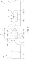
- FIG. 1 Two panels 1A, 1B are shown in a schematic sectional view, which are intended for covering a surface. Specifically, the preferred embodiment of the invention shown here is two floor panels for covering a floor area of a building. Fig. 1 shows panels 1A and 1B in an uncoupled state, i.e., separated from each other.
- the panels 1A and 1B shown here are made of thermoplastic polymers. Alternatively, they can be made of HDF or MDF.
- the two panels 1A, 1B each have a panel core enclosed by a flat panel surface 2, a flat panel bottom surface 3 spaced from and parallel to the panel surface 2, and four panel side surfaces connecting the panel surface 2 to the panel bottom surface 3.
- mutually complementary coupling elements 4, 5 in the form of an upper coupling element 4 and a lower coupling element 5 are arranged on two opposite panel side surfaces, which are designed in such a way that they enable a coupling of a first such panel 1A with a second such panel 1B by means of a relative movement of the upper coupling element 4 of the first panel 1A to the lower coupling element 5 of the second panel 1B.
- the panels 1A, 1B now each have three coupling sections on their coupling elements 4, 5, as follows:
- the upper coupling element 4 has, at its distal end, a wedge-shaped plug element 8 with an upper side 6 and a lower side 7.
- the lower coupling element 5 has a counter surface 10 which, when two panels 1A, 1B are coupled, rests against the upper side 6, so that the wedge-shaped plug element 8 or the upper side 6, together with the counter surface 10, form the first coupling section of the coupling elements 4, 5.
- the wedge-shaped plug-in element 8 has a wave-shaped surface 13A, namely the wave structure according to the invention
- the lower coupling element 5 has a plug-in receptacle 9 which adjoins the counter surface 10 and also has a wave-shaped surface 13B, into which the plug-in element 8 is inserted when two panels 1A, 1B are coupled, so that the plug-in element 8, in particular with its lower side 7, together with the plug-in receptacle 9, form the second coupling section of the coupling elements 4, 5.
- the upper coupling element 4 has a locking receptacle 1 adjoining the plug-in element 8
- the lower coupling element 5 has at its distal end a locking element 12 adjoining the plug-in receptacle 9, which engages in the locking receptacle 11 when two panels 1A, 1B are coupled, so that the locking receptacle 11 together with the locking element 12 form the third coupling section of the coupling elements 4, 5.
- the wedge-shaped plug-in element 8 is divided into two sections I, II.
- the first section I has an upper side 6I and a lower side 7I. Both sides 6I, 7I converge obliquely, with the lower side 7I being flatter than the upper side 6I. This is directly related to the fact that the angle ⁇ between the upper side 6I and a parallel P to the panel surface 2 is greater than the angle ⁇ between the lower side 7I and the parallel P.
- the first section I therefore forms a point, which facilitates handling and installation. by facilitating the insertion of the plug-in element 8 into the plug-in receptacle 9.
- the second section II is directly adjacent to the first section I and has an upper side 6II and a lower side 7II, which are straight and merge smoothly into the panel surface 2 and panel bottom surface 3, respectively.
- the surfaces 13A, 13B of the plug-in element 8 or the plug-in receptacle 9 facing each other in the coupled state of two panels 1A, 1B have complementary wave structures.
- Fig. 1 It can be seen that the wave structures in the plug-in receptacle 9 and the plug-in element 8 run perpendicular to the panel side surfaces having the mutually complementary coupling elements 4, 5 and that the wave structures in the plug-in receptacle 9 and the plug-in element 8 run sinusoidally.
- the wave structure of the upper panel 1A has one wave crest 14A less than the wave structure of the lower panel 1B has complementary wave troughs 15B.
- the oblique edge arranged instead of a wave crest 14A towards the end of the lower side 7II of the second section II facilitates the insertion of the plug-in element 8 into the plug-in receptacle 9.
- the plug-in receptacle 9 has a part 16 in the shape of a circular segment, along which the wedge-shaped tip of the first section I can slide when the plug-in element 8 is inserted into the plug-in receptacle 9, so that the tip of the plug-in element 8 is guided when the upper panel 1A is inserted into the lower panel 1B.
- the material thickness UM of the lower coupling element 5 between the panel bottom surface 3 and the plug-in receptacle 9 is smaller than the material thickness OM of the upper coupling element 4 between the panel surface 2 and the locking receptacle 11, which leads to the advantages with regard to fracture resistance mentioned in detail above.
- Fig. 2 shows the two panels 1A, 1B from Fig. 1 in a schematic sectional view during the coupling process
- the upper panel 1A is partially inserted into the lower panel 1B.
- the wedge-shaped tip of the first section I is inserted obliquely into the plug-in receptacle 9.
- Particularly easy handling is ensured by several factors: Firstly, the edge of the counter surface 10 slides along the upper side 6I of the tip; Secondly, the tip itself is guided by the circular-segment-shaped part 16, so that during a forward movement of the upper panel 1A in the x-direction, the arcuate shape of the circular-segment-shaped part 16 inevitably guides the tip upward, thus pivoting the upper panel 1A downward. Consequently, the relative movement in the form of a pivoting movement R of the upper panel 1A is forced downward during the coupling process. Faulty installation can thus be virtually ruled out. The downward movement occurs in the negative y-direction.
- Fig. 3 shows the two panels 1A, 1B from Fig. 1 and Fig. 2 in coupled state. All three coupling sections are in the coupled state.
- the plug-in element 8 is fully inserted into the plug-in receptacle 9 so that the upper side 6I rests against the counter surface 10.
- the wave crests 14A, 14B engage in the complementary wave troughs 15A, 15B.
- the locking element 12 is received by the locking receptacle 11.
- the two panels 1A, 1B are plugged into one another and can no longer be moved along the x-direction.
- the two panels 1A, 1B can only be uncoupled and thus uninstalled by a relative movement, in particular an upward pivoting movement of the upper panel essentially in the y-direction.
Landscapes
- Engineering & Computer Science (AREA)
- Architecture (AREA)
- Civil Engineering (AREA)
- Structural Engineering (AREA)
- Finishing Walls (AREA)
- Floor Finish (AREA)
Claims (11)
- Panneau (1A, 1B) pour le revêtement de surface avecun noyau de panneau entouré par une surface de panneau plate (2), une surface inférieure de panneau plate (3), espacée et parallèle à celle-ci, et quatre surfaces latérales reliant chacune la surface de panneau (2) à la surface inférieure de panneau (3),des éléments de couplage complémentaires (4, 5) étant disposés sur deux surfaces latérales opposées du panneau sous la forme d'un élément de couplage supérieur (4) et d'un élément de couplage inférieur (5), configurés de façon à permettre le couplage d'un premier panneau de ce type (1A) à un second panneau du même type (1B) au moyen d'un mouvement relatif de l'élément de couplage supérieur (4) du premier panneau (1A) vers l'élément de couplage inférieur (5) du second panneau (1B),l'élément de couplage supérieur (4) présente à son extrémité distale un élément d'enfichage en forme de coin (8) comprenant un côté supérieur (6) et un côté inférieur (7), et l'élément de couplage inférieur (5) présente à son extrémité proximale un réceptacle d'enfichage (9) avec une surface de couplage (10) dans laquelle, dans l'état accouplé de deux panneaux (1A, 1B), l'élément d'enfichage (8) peut être inséré, de sorte que le côté supérieur (6) de l'élément d'enfichage (8) forme avec la surface de couplage (10) une première section de couplage des éléments de couplage (4, 5) et le côté inférieur (7) de l'élément d'enfichage (8) forme avec le réceptacle d'enfichage (9) une deuxième section de couplage des éléments de couplage (4, 5),l'élément de couplage supérieur (4) présente un logement de verrouillage (11) adjacent à l'élément d'enfichage (8) et l'élément de couplage inférieur (5) présente à son extrémité distale un élément de verrouillage (12) adjacent au réceptacle d'enfichage (9), lequel élément de verrouillage s'engage dans le logement de verrouillage (11) dans l'état couplé des deux panneaux (1A, 1B), de sorte que le logement de verrouillage (11) forme avec l'élément de verrouillage (12) une troisième section de couplage de l'élément de couplage (4, 5), les surfaces (13A, 13B) du réceptacle d'enfichage (9) et du côté inférieur (7) de l'élément d'enfichage (8) se faisant face dans l'état couplé de deux panneaux (1A, 1B) et présentant des structures ondulées mutuellement complémentaires, de sorte que le réceptacle d'enfichage (9) présente une partie (16) s'étendant sous la forme d'une section circulaire adjacente à la surface de couplage (10), et dans laquelle les panneaux peuvent être accouplés les uns aux autres par simple insertion de l'élément d'enfichage (8) dans le réceptacle d'enfichage (9) et par pivotement ultérieur des panneaux les uns par rapport aux autres, l'extrémité en forme de coin de l'élément d'enfichage (8) glissant le long de la partie en forme de section circulaire (16) et guidée vers la position finale lorsqu'elle est insérée dans le réceptacle d'enfichage (9), et le panneau supérieur est ensuite pressé vers le bas.
- Panneau (1A, 1B) selon la revendication 1, caractérisé en ce que les structures ondulées dans le logement d'enfichage (9) et le côté inférieur (7) de l'élément d'enfichage (8) s'étendent perpendiculairement aux surfaces latérales du panneau comportant les éléments de couplage mutuellement complémentaires (4, 5).
- Panneau (1A, 1B) selon la revendication 1 ou 2, caractérisé en ce que les structures ondulées dans le réceptacle d'enfichage (9) et le côté inférieur (7) de l'élément d'enfichage (8) sont sinusoïdales.
- Panneau (1A, 1B) selon l'une des revendications précédentes, caractérisé en ce que les structures ondulées présentent au moins trois crêtes d'onde (14A, 14B).
- Panneau (1A, 1B) selon l'une des revendications précédentes, caractérisé en ce que le nombre de creux d'onde (15B) dans la structure d'onde de l'élément de couplage inférieur (5) est supérieur d'au moins un au nombre de crêtes d'onde complémentaires (14A) dans la structure d'onde de l'élément de couplage supérieur (4).
- Panneau (1A, 1B) selon l'une des revendications précédentes, caractérisé en ce que la différence de hauteur entre les crêtes d'onde (14A, 14B) et les creux d'onde (15A, 15B) est comprise entre un maximum de 7 % et un minimum de 1 % de l'épaisseur totale (G) du panneau donnée par la distance de la surface du panneau (2) à la sous-surface du panneau (3).
- Panneau (1A, 1B) selon l'une des revendications précédentes, caractérisé en ce que le panneau (1A, 1B) comprend au moins partiellement des copolymères séquencés de styrène thermoplastiques comme matériau de base.
- Panneau (1A, 1B) selon l'une des revendications précédentes, caractérisé en ce que l'élément d'enfichage en forme de coin (8) comprend une première section (I) à l'extrémité distale et une deuxième section (II) adjacente à la première section (I), une section (I, II) comprenant chacune un côté supérieur (6I, 6II) et un côté inférieur (7I, 7II), et le côté supérieur (6I) et le côté inférieur (7I) de la première section (I) sont conçus pour se rétrécir obliquement vers l'extrémité distale.
- Panneau (1A, 1B) selon l'une des revendications précédentes, caractérisé en ce que le côté supérieur (6II) et le côté inférieur (7II) de la deuxième section (II) sont chacun disposés parallèlement à la surface du panneau (2) ou à la surface inférieure (3) du panneau et le côté inférieur (7II) de la deuxième section (II) présente la structure ondulée.
- Panneau (1A, 1B) selon l'une des revendications précédentes, caractérisé en ce qu'un premier angle (α) entre le côté supérieur (6I) de la première section (I) et une parallèle (P) à la surface du panneau (2) ou à la surface inférieure (3) du panneau est supérieur à un deuxième angle (β) entre le côté inférieur (71) de la première section (I) et la parallèle (P).
- Panneau (1A, 1B) selon l'une des revendications précédentes, caractérisé en ce que la somme du premier angle (α) et du deuxième angle (β) est inférieure à 90°.
Priority Applications (1)
| Application Number | Priority Date | Filing Date | Title |
|---|---|---|---|
| EP21195332.8A EP4144932B1 (fr) | 2021-09-07 | 2021-09-07 | Panneau de revêtement d'une surface |
Applications Claiming Priority (1)
| Application Number | Priority Date | Filing Date | Title |
|---|---|---|---|
| EP21195332.8A EP4144932B1 (fr) | 2021-09-07 | 2021-09-07 | Panneau de revêtement d'une surface |
Publications (2)
| Publication Number | Publication Date |
|---|---|
| EP4144932A1 EP4144932A1 (fr) | 2023-03-08 |
| EP4144932B1 true EP4144932B1 (fr) | 2025-05-07 |
Family
ID=77666258
Family Applications (1)
| Application Number | Title | Priority Date | Filing Date |
|---|---|---|---|
| EP21195332.8A Active EP4144932B1 (fr) | 2021-09-07 | 2021-09-07 | Panneau de revêtement d'une surface |
Country Status (1)
| Country | Link |
|---|---|
| EP (1) | EP4144932B1 (fr) |
Family Cites Families (3)
| Publication number | Priority date | Publication date | Assignee | Title |
|---|---|---|---|---|
| DE19851200C1 (de) * | 1998-11-06 | 2000-03-30 | Kronotex Gmbh Holz Und Kunstha | Fußbodenpaneele |
| FR2922568B1 (fr) * | 2007-10-23 | 2016-11-11 | Mprin Parquets Sa | Panneau de recouvrement de sol a profil encliquetable |
| CN102803625B (zh) * | 2010-01-11 | 2014-12-31 | 韦林奇创新公司 | 具有互锁设计的地板覆盖物 |
-
2021
- 2021-09-07 EP EP21195332.8A patent/EP4144932B1/fr active Active
Also Published As
| Publication number | Publication date |
|---|---|
| EP4144932A1 (fr) | 2023-03-08 |
Similar Documents
| Publication | Publication Date | Title |
|---|---|---|
| EP2250330B1 (fr) | Procédé d'application de panneaux de sol | |
| AT411542B (de) | Zusammensteckbare einzelteile, insbesondere für einen fussbodenbelag | |
| EP1294995B1 (fr) | Système de plancher comprenant un pluralité de planches de plancher identiques | |
| DE69927394T2 (de) | Fussbodensystem mit in vertikaler Richtung zu verbindenen Fussbodenplatten und mit separaten Verbindungsprofilen | |
| DE60000632T2 (de) | Artikel mit ineinandergreifbaren Rändern und daraus hergestelltes Abdeckungsprodukt | |
| DE60221788T2 (de) | Fussbodensystem umfassend mehrere mechanisch verbindbaren Fussbodenplatten | |
| DE60129796T2 (de) | Fussbodenbelag umfassend Fussbodenplatten mit integrierten Verbindungsmitteln, die durch vertikale Absenkbewegung miteinander verrastbar sind | |
| EP2795017B1 (fr) | Panneau d'un revêtement de sol comportant une surface de verrouillage inclinée le long d'une arête latérale | |
| DE202016102034U1 (de) | Fußbodenpaneel zur Bildung eines Fußbodenbelags | |
| WO2005054600A1 (fr) | Carreau | |
| DE05077327T1 (de) | Fußbodenbelag, bestehend aus harten Fußbodenpaneelen und Verfahren zur Herstellung solcher Fußbodenpaneele | |
| DE20203311U1 (de) | Paneelelement | |
| EP2989269A1 (fr) | Dalle de plancher, en particulier pour planchers | |
| EP4407121A2 (fr) | Panneau mural ou de plancher avec moyens de verrouillage appropriés pour la pose en chevrons | |
| WO2010128043A1 (fr) | Systèmes de verrouillage pour panneaux | |
| DE60213360T2 (de) | Fussbodensystem mit Fussbodenplatten und Verfahren zur Verbindung derartiger Platten | |
| DE10232508C1 (de) | Fussbodenpaneel | |
| DE20010913U1 (de) | Platte | |
| EP0973983B1 (fr) | Element plat de type carreau | |
| EP4144932A1 (fr) | Panneau de revêtement d'une surface | |
| EP4144933B1 (fr) | Panneau de revêtement d'une surface | |
| WO2013023639A1 (fr) | Revêtement composé de panneaux pouvant être reliés mécaniquement entre eux | |
| EP2885470A1 (fr) | Garniture composée d'éléments pouvant être reliés mécaniquement les uns aux autres | |
| AT500338B1 (de) | Erzeugnis mit einer steckkante und einer aufnahmekante | |
| DE102006055715A1 (de) | Bodenelement in Form einer verlegbare Bodenplatte und damit gebildeter Verbund |
Legal Events
| Date | Code | Title | Description |
|---|---|---|---|
| PUAI | Public reference made under article 153(3) epc to a published international application that has entered the european phase |
Free format text: ORIGINAL CODE: 0009012 |
|
| STAA | Information on the status of an ep patent application or granted ep patent |
Free format text: STATUS: THE APPLICATION HAS BEEN PUBLISHED |
|
| AK | Designated contracting states |
Kind code of ref document: A1 Designated state(s): AL AT BE BG CH CY CZ DE DK EE ES FI FR GB GR HR HU IE IS IT LI LT LU LV MC MK MT NL NO PL PT RO RS SE SI SK SM TR |
|
| P01 | Opt-out of the competence of the unified patent court (upc) registered |
Effective date: 20230526 |
|
| STAA | Information on the status of an ep patent application or granted ep patent |
Free format text: STATUS: REQUEST FOR EXAMINATION WAS MADE |
|
| 17P | Request for examination filed |
Effective date: 20230907 |
|
| RBV | Designated contracting states (corrected) |
Designated state(s): AL AT BE BG CH CY CZ DE DK EE ES FI FR GB GR HR HU IE IS IT LI LT LU LV MC MK MT NL NO PL PT RO RS SE SI SK SM TR |
|
| GRAP | Despatch of communication of intention to grant a patent |
Free format text: ORIGINAL CODE: EPIDOSNIGR1 |
|
| STAA | Information on the status of an ep patent application or granted ep patent |
Free format text: STATUS: GRANT OF PATENT IS INTENDED |
|
| RIC1 | Information provided on ipc code assigned before grant |
Ipc: E04F 15/02 20060101AFI20241115BHEP |
|
| INTG | Intention to grant announced |
Effective date: 20241210 |
|
| GRAS | Grant fee paid |
Free format text: ORIGINAL CODE: EPIDOSNIGR3 |
|
| GRAA | (expected) grant |
Free format text: ORIGINAL CODE: 0009210 |
|
| STAA | Information on the status of an ep patent application or granted ep patent |
Free format text: STATUS: THE PATENT HAS BEEN GRANTED |
|
| AK | Designated contracting states |
Kind code of ref document: B1 Designated state(s): AL AT BE BG CH CY CZ DE DK EE ES FI FR GB GR HR HU IE IS IT LI LT LU LV MC MK MT NL NO PL PT RO RS SE SI SK SM TR |
|
| REG | Reference to a national code |
Ref country code: GB Ref legal event code: FG4D Free format text: NOT ENGLISH |
|
| REG | Reference to a national code |
Ref country code: CH Ref legal event code: EP |
|
| REG | Reference to a national code |
Ref country code: DE Ref legal event code: R096 Ref document number: 502021007390 Country of ref document: DE |
|
| REG | Reference to a national code |
Ref country code: IE Ref legal event code: FG4D Free format text: LANGUAGE OF EP DOCUMENT: GERMAN |
|
| REG | Reference to a national code |
Ref country code: NL Ref legal event code: MP Effective date: 20250507 |
|
| PG25 | Lapsed in a contracting state [announced via postgrant information from national office to epo] |
Ref country code: ES Free format text: LAPSE BECAUSE OF FAILURE TO SUBMIT A TRANSLATION OF THE DESCRIPTION OR TO PAY THE FEE WITHIN THE PRESCRIBED TIME-LIMIT Effective date: 20250507 Ref country code: FI Free format text: LAPSE BECAUSE OF FAILURE TO SUBMIT A TRANSLATION OF THE DESCRIPTION OR TO PAY THE FEE WITHIN THE PRESCRIBED TIME-LIMIT Effective date: 20250507 Ref country code: PT Free format text: LAPSE BECAUSE OF FAILURE TO SUBMIT A TRANSLATION OF THE DESCRIPTION OR TO PAY THE FEE WITHIN THE PRESCRIBED TIME-LIMIT Effective date: 20250908 |
|
| PGFP | Annual fee paid to national office [announced via postgrant information from national office to epo] |
Ref country code: DE Payment date: 20250924 Year of fee payment: 5 |
|
| REG | Reference to a national code |
Ref country code: LT Ref legal event code: MG9D |
|
| PG25 | Lapsed in a contracting state [announced via postgrant information from national office to epo] |
Ref country code: NO Free format text: LAPSE BECAUSE OF FAILURE TO SUBMIT A TRANSLATION OF THE DESCRIPTION OR TO PAY THE FEE WITHIN THE PRESCRIBED TIME-LIMIT Effective date: 20250807 Ref country code: GR Free format text: LAPSE BECAUSE OF FAILURE TO SUBMIT A TRANSLATION OF THE DESCRIPTION OR TO PAY THE FEE WITHIN THE PRESCRIBED TIME-LIMIT Effective date: 20250808 |
|
| PG25 | Lapsed in a contracting state [announced via postgrant information from national office to epo] |
Ref country code: NL Free format text: LAPSE BECAUSE OF FAILURE TO SUBMIT A TRANSLATION OF THE DESCRIPTION OR TO PAY THE FEE WITHIN THE PRESCRIBED TIME-LIMIT Effective date: 20250507 Ref country code: PL Free format text: LAPSE BECAUSE OF FAILURE TO SUBMIT A TRANSLATION OF THE DESCRIPTION OR TO PAY THE FEE WITHIN THE PRESCRIBED TIME-LIMIT Effective date: 20250507 |
|
| PG25 | Lapsed in a contracting state [announced via postgrant information from national office to epo] |
Ref country code: BG Free format text: LAPSE BECAUSE OF FAILURE TO SUBMIT A TRANSLATION OF THE DESCRIPTION OR TO PAY THE FEE WITHIN THE PRESCRIBED TIME-LIMIT Effective date: 20250507 |
|
| PG25 | Lapsed in a contracting state [announced via postgrant information from national office to epo] |
Ref country code: HR Free format text: LAPSE BECAUSE OF FAILURE TO SUBMIT A TRANSLATION OF THE DESCRIPTION OR TO PAY THE FEE WITHIN THE PRESCRIBED TIME-LIMIT Effective date: 20250507 |
|
| PGFP | Annual fee paid to national office [announced via postgrant information from national office to epo] |
Ref country code: AT Payment date: 20251020 Year of fee payment: 5 |
|
| PG25 | Lapsed in a contracting state [announced via postgrant information from national office to epo] |
Ref country code: RS Free format text: LAPSE BECAUSE OF FAILURE TO SUBMIT A TRANSLATION OF THE DESCRIPTION OR TO PAY THE FEE WITHIN THE PRESCRIBED TIME-LIMIT Effective date: 20250807 |
|
| PG25 | Lapsed in a contracting state [announced via postgrant information from national office to epo] |
Ref country code: IS Free format text: LAPSE BECAUSE OF FAILURE TO SUBMIT A TRANSLATION OF THE DESCRIPTION OR TO PAY THE FEE WITHIN THE PRESCRIBED TIME-LIMIT Effective date: 20250907 |
|
| PG25 | Lapsed in a contracting state [announced via postgrant information from national office to epo] |
Ref country code: LV Free format text: LAPSE BECAUSE OF FAILURE TO SUBMIT A TRANSLATION OF THE DESCRIPTION OR TO PAY THE FEE WITHIN THE PRESCRIBED TIME-LIMIT Effective date: 20250507 |
|
| PG25 | Lapsed in a contracting state [announced via postgrant information from national office to epo] |
Ref country code: DK Free format text: LAPSE BECAUSE OF FAILURE TO SUBMIT A TRANSLATION OF THE DESCRIPTION OR TO PAY THE FEE WITHIN THE PRESCRIBED TIME-LIMIT Effective date: 20250507 Ref country code: SM Free format text: LAPSE BECAUSE OF FAILURE TO SUBMIT A TRANSLATION OF THE DESCRIPTION OR TO PAY THE FEE WITHIN THE PRESCRIBED TIME-LIMIT Effective date: 20250507 |
|
| PG25 | Lapsed in a contracting state [announced via postgrant information from national office to epo] |
Ref country code: CZ Free format text: LAPSE BECAUSE OF FAILURE TO SUBMIT A TRANSLATION OF THE DESCRIPTION OR TO PAY THE FEE WITHIN THE PRESCRIBED TIME-LIMIT Effective date: 20250507 |
|
| PG25 | Lapsed in a contracting state [announced via postgrant information from national office to epo] |
Ref country code: EE Free format text: LAPSE BECAUSE OF FAILURE TO SUBMIT A TRANSLATION OF THE DESCRIPTION OR TO PAY THE FEE WITHIN THE PRESCRIBED TIME-LIMIT Effective date: 20250507 |
|
| PG25 | Lapsed in a contracting state [announced via postgrant information from national office to epo] |
Ref country code: SK Free format text: LAPSE BECAUSE OF FAILURE TO SUBMIT A TRANSLATION OF THE DESCRIPTION OR TO PAY THE FEE WITHIN THE PRESCRIBED TIME-LIMIT Effective date: 20250507 |
|
| PG25 | Lapsed in a contracting state [announced via postgrant information from national office to epo] |
Ref country code: IT Free format text: LAPSE BECAUSE OF FAILURE TO SUBMIT A TRANSLATION OF THE DESCRIPTION OR TO PAY THE FEE WITHIN THE PRESCRIBED TIME-LIMIT Effective date: 20250507 |
|
| PG25 | Lapsed in a contracting state [announced via postgrant information from national office to epo] |
Ref country code: RO Free format text: LAPSE BECAUSE OF FAILURE TO SUBMIT A TRANSLATION OF THE DESCRIPTION OR TO PAY THE FEE WITHIN THE PRESCRIBED TIME-LIMIT Effective date: 20250507 |
|
| REG | Reference to a national code |
Ref country code: DE Ref legal event code: R097 Ref document number: 502021007390 Country of ref document: DE |
|
| PLBE | No opposition filed within time limit |
Free format text: ORIGINAL CODE: 0009261 |
|
| STAA | Information on the status of an ep patent application or granted ep patent |
Free format text: STATUS: NO OPPOSITION FILED WITHIN TIME LIMIT |
|
| REG | Reference to a national code |
Ref country code: CH Ref legal event code: L10 Free format text: ST27 STATUS EVENT CODE: U-0-0-L10-L00 (AS PROVIDED BY THE NATIONAL OFFICE) Effective date: 20260318 |
|
| 26N | No opposition filed |
Effective date: 20260210 |
|
| REG | Reference to a national code |
Ref country code: CH Ref legal event code: H13 Free format text: ST27 STATUS EVENT CODE: U-0-0-H10-H13 (AS PROVIDED BY THE NATIONAL OFFICE) Effective date: 20260504 |