EP4144941A1 - Einstellbares schliessblech - Google Patents
Einstellbares schliessblech Download PDFInfo
- Publication number
- EP4144941A1 EP4144941A1 EP22193210.6A EP22193210A EP4144941A1 EP 4144941 A1 EP4144941 A1 EP 4144941A1 EP 22193210 A EP22193210 A EP 22193210A EP 4144941 A1 EP4144941 A1 EP 4144941A1
- Authority
- EP
- European Patent Office
- Prior art keywords
- flank
- stop member
- teeth
- retaining
- hooking
- Prior art date
- Legal status (The legal status is an assumption and is not a legal conclusion. Google has not performed a legal analysis and makes no representation as to the accuracy of the status listed.)
- Granted
Links
Images


Classifications
-
- E—FIXED CONSTRUCTIONS
- E05—LOCKS; KEYS; WINDOW OR DOOR FITTINGS; SAFES
- E05B—LOCKS; ACCESSORIES THEREFOR; HANDCUFFS
- E05B15/00—Other details of locks; Parts for engagement by bolts of fastening devices
- E05B15/02—Striking-plates; Keepers; Bolt staples; Escutcheons
- E05B15/0205—Striking-plates, keepers, staples
- E05B15/024—Striking-plates, keepers, staples adjustable
- E05B15/0245—Movable elements held by friction, cooperating teeth, or the like
-
- E—FIXED CONSTRUCTIONS
- E05—LOCKS; KEYS; WINDOW OR DOOR FITTINGS; SAFES
- E05B—LOCKS; ACCESSORIES THEREFOR; HANDCUFFS
- E05B15/00—Other details of locks; Parts for engagement by bolts of fastening devices
- E05B15/02—Striking-plates; Keepers; Bolt staples; Escutcheons
- E05B15/0205—Striking-plates, keepers, staples
- E05B15/022—Striking-plates, keepers, staples movable, resilient or yieldable
-
- E—FIXED CONSTRUCTIONS
- E05—LOCKS; KEYS; WINDOW OR DOOR FITTINGS; SAFES
- E05B—LOCKS; ACCESSORIES THEREFOR; HANDCUFFS
- E05B17/00—Accessories in connection with locks
- E05B17/0025—Devices for forcing the wing firmly against its seat or to initiate the opening of the wing
Definitions
- the present invention relates to an adjustable keeper for a frame capable of receiving a leaf equipped with a mechanism provided with a retractable bolt.
- a field of application envisaged is in particular, but not exclusively, that of anti-panic locks making it possible to easily open in a hurry, a leaf, or a door, from the inside of a building towards the outside, when it is locked from the outside inwards.
- doors called “emergency doors”, come to close an opening delimited by a frame.
- Known adjustable latches comprise a housing having a face intended to be applied against the amount of a fixed frame and to be screwed therein.
- the latches further comprise a substantially prismatic stop member and mounted adjustable inside the case by means of two suitable screws.
- the stop member has a front edge and two sides opposite each other with respect to this front edge. Thus, one of the flanks of the stop member is oriented inwards, while the other is oriented outwards.
- the fixed frame receives the hinged mounted leaf vertically on the other upright of the fixed frame and opposite the adjustable keeper. And the leaf is equipped with a locking mechanism provided with a retractable bolt adapted to cooperate with the keeper.
- the leaf is for example recalled by a door closer and when the latter pivots it to close the opening, the retractable bolt comes into abutment against one of the sides of the stop member and it then retracts to allow the leaf to continue its travel and come to engage completely inside the frame, while the bolt returns behind the stopper to come to rest against its opposite side. The leaf is then held in a fixed position inside the frame.
- the keeper, and more specifically the stopper is adjustable inside the housing so as to be able to precisely adjust the relative position of the retractable bolt and of the stopper for optimal locking.
- This adjustment is made when fitting the leaf in the frame and the strike. And it can also be achieved when the frame and the leaf change over time and their relative position deviates from the original position. This development may be due to the aging of the building, for example, to expansion or the frequency of stresses. And it can then cause a locking fault.
- a problem which arises and which the present invention aims to solve is to provide an adjustable keeper requiring less supervision and therefore, which is less expensive to operate, in order to be able to obtain the best possible closure of the leaf in the fixed frame.
- an adjustable keeper comprising a casing adapted to be mounted on a fixed frame, said fixed frame being capable of receiving a leaf fitted with a mechanism provided with a retractable bolt; and, a stopper member mounted adjustable inside said casing, said stopper member having a front edge and two flanks opposite each other with respect to said front ridge, one of said flanks being adapted to receive said retractable bolt in abutment to cause the retraction of said bolt and to authorize the engagement of said leaf inside said fixed frame, while said bolt returns to bear against the other flank of said two flanks in order to be able to maintain said leaf in a fixed position inside said frame.
- Said box has on the inside a bearing surface provided with retaining teeth, while said stopper has hooking teeth extending in said one of said flanks, and said stopper is adapted to be retracted inside said housing when said bolt comes into abutment against said one of said flanks and then extends from said housing to come into contact with said bolt, while said hooking teeth come into engagement in said retaining teeth to prevent the retraction of said stop member when said bolt bears against said other side.
- a characteristic of the invention resides in the implementation of a self-adjusting stop member.
- the stop member adjusts itself in an optimal position for retaining the retractable bolt. And this, regardless of the relative dimensional changes of the frame and the leaf over time and stress.
- said stop member retracts inside said box when said bolt comes to dock with one of said flanks, while the retractable bolt itself retracts inside its mechanism.
- the retractable bolt is released.
- the stop member also relaxes and then cooperates with the retractable bolt so that the other side comes into contact with the retractable bolt.
- the retractable bolt then comes, via the leaf, to exert a force on the other side of the stop member. This causes the engagement of the hooking teeth and the retaining teeth and hence the blocking of the stop member in the direction of retraction.
- the stop member extends into the free space which extends between the housing and the retractable bolt until it comes into contact with it. And it is thanks to this feature that the strike object of the invention is self-adjusting.
- the adjustable keeper comprises a return spring mounted inside said casing to cause said stop member to extend.
- the return spring has a predetermined stiffness which should be defined according to the force to be provided to retract the retractable bolt.
- said housing comprises a bearing face and a free edge running along said bearing face and said bearing face, and said retaining teeth have a retaining generatrix substantially parallel to said free edge.
- the stop member is movable in translation in a direction perpendicular to the free edge and to the retaining teeth.
- said retaining teeth each have a retaining flank oriented towards the outside of said housing, said retaining flank being inclined along a mean plane close to a plane perpendicular to said bearing face.
- said retaining teeth each have a first sliding flank opposite said retaining flank, said first sliding flank being inclined at a substantially right angle with respect to said retaining flank.
- the retaining teeth are asymmetrical.
- such a geometry of the first sliding flanks makes it possible to facilitate the extension of the stop member towards the outside of the case.
- said hooking teeth have a hooking generatrix substantially parallel to said front edge.
- the hooking teeth extend in a direction parallel to the front edge and perpendicular to the direction of translation of the stop member. In this way, the hooking teeth cooperate perfectly with the retaining teeth. Because in fact, the hooking teeth extend in a common transverse direction to the retaining teeth.
- said hooking teeth each have a second sliding flank opposite said hooking flank, said second sliding flank being inclined substantially at a right angle relative to said hooking flank.
- the first sliding flank of the retaining teeth cooperates with the second sliding flank of the hooking teeth when the stop member is driven towards the outside of the housing. In this way, driving the stop member is facilitated. Also, during this movement, the stop member tends to move away from the bearing face. Furthermore, the stop member has a clearance in a direction perpendicular to the bearing face of the housing as will be explained below.
- said other flank of said stop member is of cylindrical shape defined by a generatrix parallel to said front edge.
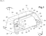
- FIG. 1 shows an adjustable keeper 10 comprising a casing 12 inside which is installed a stop member 14.
- the casing 12 has a bearing wall 16 opposite a longitudinal covering wall 18 substantially parallel.
- the longitudinal covering wall 18 is connected to the support wall 16, via two opposite inclined trapezoidal walls 20, 22 and a rear wall 24, which also joins the two opposite trapezoidal walls 20, 22.
- the housing 12 has an opening 26 located opposite the rear wall 24.
- the opening 26 is delimited in particular by a free edge 25 of the support wall 16.
- the housing 12 has, inside, a support face 28 on which the stop member 14 comes to rest. support 28.
- the support wall 16 defines a mean plane and the support face 28 defines another mean plane substantially parallel to the mean plane of the support wall 16.
- the stopper 14 has a front edge 30 and on one side of the front edge 30, a flat flank 32, and on the opposite side, a cylindrical flank 34.
- the flat flank 32 extends along the same mean plane, up to a heel 35 of the stop member 14.
- the stop member 14 also has two opposite side faces 36, 38.
- the two opposite side faces 36, 38 join a guide face 45, substantially parallel to the flat side 32 and which extends in the extension of the cylindrical side 34 .
- the stop member 14 is held between two free wings 40, 42 located respectively equidistant from the two trapezoidal walls 20, 22.
- the two free wings 40, 42 extend inside the housing 12 from the wall longitudinal cover 18 and the rear wall 24.
- the two free flanges 40, 42 have two guide edges 44, 46 which extend substantially equidistant between the longitudinal covering wall 18 and the bearing face 28 in a direction substantially parallel to the bearing face. 28.
- the stop member 14 comprises two lateral ribs 48, 50 extending projecting from the two opposite lateral faces 36, 38.
- the two lateral ribs 48, 50 extend substantially parallel to the aforementioned mean plane defined by the flat side 32. Also, the two lateral ribs 48, 50 are adapted to come into sliding contact respectively against the guide edges 44, 46.
- the stop member 14 is movable in translation inside the casing 12 in a direction perpendicular to the bearing surface 28 according to a small amplitude which will be specified later.
- the lateral ribs 48, 50 bear against the guide edge 44, 46, the flat flank 32 is substantially away from the bearing face 28 of the housing 12.
- the guide face 45 is in sliding contact against the longitudinal covering wall 18 of the housing 12.
- the box 12 has two fixing screws 52, 54 located on each side of the stop member 14 and which extend through the support wall 16.
- the box 12 is then adapted to be connected to the upright of a fixed frame (not shown), the applied face 29 of the bearing wall 16 applied against the fixed frame and the two fastening screws 52, 54 screwed into it.
- a helical spring, 56 extends into a housing 58 provided in the heel 35 of the stopper 14.
- Housing 58 of cylindrical shape, extends inside stopper 14 parallel to flat side 32 in a direction substantially perpendicular to front edge 30.
- the housing 58 has a stop wall 60 inclined with respect to the flat side 32 and against which the helical spring 56 is applied. More precisely, the stop wall 60 has a normal which intersects the cylindrical side 34. Thus , the helical spring 56 tends to push the stop member 14 towards the outside of the housing 12. In addition, thanks to the inclined stop wall 60, which forms a ramp by cooperating with the helical spring 56, the member stop 14 tends to be spaced substantially from the bearing face 28, as will be explained below.
- the flat side 32 of the stop member 14 has a plurality of hooking teeth 70, defined by a generatrix substantially parallel to the front edge 30.
- Each of the hooking teeth 70 has a flank hooking flank 72 oriented opposite the front edge 30, and a second sliding flank 74 opposite the hooking flank 72.
- the hooking flank 72 and the second sliding flank 74 meet at a vertex of hooking 76.
- the hooking flank 72 is inclined along a mean plane close to a plane perpendicular to the flat flank 32.
- the second sliding flank 74 is substantially perpendicular to the hooking flank 72.
- hooking teeth 70 of the plurality of hooking teeth are also identical.
- the retractable bolt 78 As for the retractable bolt 78, it extends projecting from a faceplate 82 and it is pivotally mounted around a pivot axis P located inside the lock 80. As shown in [ Fig. 3 ], the retractable bolt 78 is in its position of rest and maximum extension outside the lock 80. In other words, it is locked in rotation in the direction of clockwise.
- pivot axis P of the retractable bolt 78 is oriented in a direction substantially parallel to the pivot axis of the leaf.
- the retractable bolt 78 has a docking face 84 and, opposite, a cylindrical retaining surface 86.
- the docking face 84 and the cylindrical retaining surface 86 meet at a crest 88.
- the retractable bolt 78 is on the [ Fig. 3 ] at rest, and the docking face 84 is inclined relative to the headrest 82 by approximately 135°.
- the cylindrical retaining surface 86 joins the docking face 84 at the level of the crest 88 substantially at 90°.
- the lock 80 and consequently the retractable bolt 78 also pivot, and the retractable bolt 78 is driven along a substantially rectilinear trajectory along the arrow F, given the distance which extends between the lock 80 and the pivot axis of the leaf.
- the docking face 84 of the retractable bolt 78 will come into abutment against the flat side 32 of the stop member 14, in the vicinity of the front edge 30. Consequently, the stop member 14 is first driven in movement relative to the housing 12, according to a component perpendicular to the bearing face 28 of the housing, so that the ribs 48, 50 of the stop member 14 as illustrated in [ Fig. 1 ] come to bear against the guide edge 44, 46 of the two free flanges 40, 42. In this way, the flat side 32 of the stop member 14 moves away from the bearing face 28, and the plurality of hooking teeth 70 escapes the reach of the plurality of retaining teeth 62.
- the maximum amplitude of the movement of the stop member 14 according to said component perpendicular to the bearing face 28, is substantially greater than the height of the retaining teeth 62 and the attachment teeth 70.
- the leaf continuing its course, also causes the pivoting of the retractable bolt 78 towards the inside of the lock 80 around the pivot axis P.
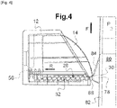
- the retractable bolt 78 while maintaining the stop member 14 spaced from the bearing face 28 of the casing, causes its retraction according to the arrow R inside the casing 12, by compressing the helical spring 56, as shown in the [ Fig. 4 ]. It will be observed that the front edge 30 of the stop member 14 is then in sliding contact against the docking face 84.
- the lock 80 continues its movement according to the arrow F.
- the crest 88 of the retractable bolt 78 then joins the front edge 30 of the stop member 14 which is substantially parallel to it, and the bolt retractable 78 is then retracted to its maximum level. Then, after the passage of the front edge 30, the retractable bolt 78 can escape the reach of the stop member 14. And the leaf comes to rest against the elements of the frame which come to stop its travel.
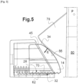
- the stop member 14 also relaxes under the action of the helical spring 56 which relaxes. The stop member 14 is then driven in movement towards the outside of the housing 12; and this, until the cylindrical side 34 comes into abutment against the cylindrical retaining surface 86 of the retractable bolt 78.
- the dimensions of the stopper 14 and of the casing 12 allow a maximum amplitude of ejection of the stopper 14, to adapt to the maximum relative deformations which the leaf and the frame can undergo.
- the force E is exerted by the retractable bolt 78 on the cylindrical side 34 near the guide face 45 of the stop member 14. And it is exerted towards the bearing face 28.
- the stop member 14 is driven in translation inside the housing 12, and the flat flank 32 bears against the bearing face 28, while the plurality of hooking teeth 70 engages in the plurality retaining teeth 62. More specifically, the hooking flanks 72 bear against the retaining flanks 64.
- the stop member 14 Since the joint plane between the hooking flanks 72 and the retaining flanks 64 is inclined in a direction close to a direction perpendicular to the bearing face 28, the stop member 14 is perfectly blocked in translation in the meaning of retraction. Moreover, thanks to the pressure exerted by the leaf via the retractable bolt 78, the blocking of the stopper 14 is ensured.
- the leaf is itself immobilized in the closed position thanks to the retractable bolt 78.
- the opening of the leaf can only be done by unlocking the lock 80 and therefore, by again causing the pivoting of the retractable bolt 78 towards the inside of the lock 80.
Landscapes
- Lock And Its Accessories (AREA)
- Preliminary Treatment Of Fibers (AREA)
- Seats For Vehicles (AREA)
Priority Applications (1)
| Application Number | Priority Date | Filing Date | Title |
|---|---|---|---|
| MA62470A MA62470B1 (fr) | 2021-08-31 | 2022-08-31 | Gâche réglable |
Applications Claiming Priority (1)
| Application Number | Priority Date | Filing Date | Title |
|---|---|---|---|
| FR2109079A FR3126437B1 (fr) | 2021-08-31 | 2021-08-31 | Gâche réglable |
Publications (2)
| Publication Number | Publication Date |
|---|---|
| EP4144941A1 true EP4144941A1 (de) | 2023-03-08 |
| EP4144941B1 EP4144941B1 (de) | 2024-08-07 |
Family
ID=78049407
Family Applications (1)
| Application Number | Title | Priority Date | Filing Date |
|---|---|---|---|
| EP22193210.6A Active EP4144941B1 (de) | 2021-08-31 | 2022-08-31 | Einstellbares schliessblech |
Country Status (6)
| Country | Link |
|---|---|
| EP (1) | EP4144941B1 (de) |
| ES (1) | ES2991792T3 (de) |
| FR (1) | FR3126437B1 (de) |
| MA (1) | MA62470B1 (de) |
| PL (1) | PL4144941T3 (de) |
| PT (1) | PT4144941T (de) |
Citations (4)
| Publication number | Priority date | Publication date | Assignee | Title |
|---|---|---|---|---|
| US2904367A (en) * | 1957-04-23 | 1959-09-15 | Bennett Patrick John | Door latch device |
| NL8701748A (nl) * | 1987-07-23 | 1989-02-16 | Buva Bv | Sluitplaat. |
| EP0362040B1 (de) * | 1988-09-26 | 1992-07-15 | Vachette | Einstellbares Schliessblech für ein Schloss, insbesondere für Kraftfahrzeughauben oder -türen und Schloss mit solchem Schliessblech |
| DE102007018871A1 (de) * | 2006-05-15 | 2007-11-22 | Kfv Karl Fliether Gmbh & Co. Kg | Gegenschließteil mit schwenkbarer Sperrplatte |
-
2021
- 2021-08-31 FR FR2109079A patent/FR3126437B1/fr active Active
-
2022
- 2022-08-31 EP EP22193210.6A patent/EP4144941B1/de active Active
- 2022-08-31 MA MA62470A patent/MA62470B1/fr unknown
- 2022-08-31 PL PL22193210.6T patent/PL4144941T3/pl unknown
- 2022-08-31 PT PT221932106T patent/PT4144941T/pt unknown
- 2022-08-31 ES ES22193210T patent/ES2991792T3/es active Active
Patent Citations (4)
| Publication number | Priority date | Publication date | Assignee | Title |
|---|---|---|---|---|
| US2904367A (en) * | 1957-04-23 | 1959-09-15 | Bennett Patrick John | Door latch device |
| NL8701748A (nl) * | 1987-07-23 | 1989-02-16 | Buva Bv | Sluitplaat. |
| EP0362040B1 (de) * | 1988-09-26 | 1992-07-15 | Vachette | Einstellbares Schliessblech für ein Schloss, insbesondere für Kraftfahrzeughauben oder -türen und Schloss mit solchem Schliessblech |
| DE102007018871A1 (de) * | 2006-05-15 | 2007-11-22 | Kfv Karl Fliether Gmbh & Co. Kg | Gegenschließteil mit schwenkbarer Sperrplatte |
Also Published As
| Publication number | Publication date |
|---|---|
| FR3126437B1 (fr) | 2023-11-24 |
| PT4144941T (pt) | 2024-10-02 |
| PL4144941T3 (pl) | 2024-12-16 |
| FR3126437A1 (fr) | 2023-03-03 |
| ES2991792T3 (es) | 2024-12-04 |
| EP4144941B1 (de) | 2024-08-07 |
| MA62470B1 (fr) | 2024-09-30 |
Similar Documents
| Publication | Publication Date | Title |
|---|---|---|
| EP0533533A1 (de) | Verriegelte Schachtabdeckung | |
| EP4190998A1 (de) | Vorrichtung zum halten eines flügels | |
| EP0801196B1 (de) | Beschlag für Tür, Fenster oder ähnlich, insbesondere ein Schliessblech, bestimmt für Montage auf einem Profil aus Aluminium oder PVC | |
| EP4144941B1 (de) | Einstellbares schliessblech | |
| EP2650460A2 (de) | Vorrichtung zum provisorischen Verschließen eines Öffnungselements auf einem Rahmenelement | |
| EP1336716B1 (de) | Befestigungsvorrichtung für einen Verschlussdeckel auf einem Rolladenkasten | |
| EP1030015B1 (de) | Verriegelungsbeschlag des Typs mit Treibstangen oder ähnlichem | |
| EP2318622A1 (de) | Vorrichtung zum vorübergehenden schliessen einer zu öffnenden platte auf einem trägerelement | |
| EP0504044B1 (de) | Schrank mit verriegelbarer und umwendbarer Tür, und ein System mit einem solchen Schrank | |
| EP1045107B1 (de) | Rolladen mit einer durch Winkelprofile gehaltenen Wickelwelle | |
| EP1880072B1 (de) | Mit zwei in längsrichtung versetzten verriegelungspositionen versehenes schloss | |
| EP1808557B1 (de) | Verriegelungsbeschlag | |
| EP1808560B1 (de) | Verschlussvorrichtung für einen Kasten | |
| FR2699588A1 (fr) | Bloc-porte à montage réversible avec ouverture à droite ou à gauche. | |
| FR2926579A1 (fr) | Serrure de securite renforcee | |
| EP3530851B1 (de) | Verriegelungssystem für eine brandschutztür mit seitlicher verschiebung | |
| EP2907947B1 (de) | Verriegelungsvorrichtung für halbfesten Fenster- oder Türflügel | |
| EP1475497A1 (de) | Sperriegel für Tür- oder Fensterflügel | |
| EP1407909B1 (de) | Schliesseinrichtung für eine in einer Kraftfahrzeugkarrosserie angeordnete Öffnung mit einem beweglichen und verschwenkbaren Deckel | |
| EP3081725B1 (de) | Zwischenbeschlag für schliesssystem | |
| EP0805250B1 (de) | Feststeller für Tür, Fenster oder sonstiges | |
| FR3159620A1 (fr) | Système de maintien d’un vantail mobile | |
| EP4105419A1 (de) | Perfektionierte vorrichtung zum provisorischen schliessen eines öffnungselements auf einem halterungselement | |
| FR3161701A1 (fr) | Dispositif d’ouverture et de fermeture d’une serrure multipoints | |
| FR3102435A1 (fr) | Véhicule automobile utilitaire muni d’une cloison de séparation transversale à porte pivotante |
Legal Events
| Date | Code | Title | Description |
|---|---|---|---|
| PUAI | Public reference made under article 153(3) epc to a published international application that has entered the european phase |
Free format text: ORIGINAL CODE: 0009012 |
|
| STAA | Information on the status of an ep patent application or granted ep patent |
Free format text: STATUS: THE APPLICATION HAS BEEN PUBLISHED |
|
| AK | Designated contracting states |
Kind code of ref document: A1 Designated state(s): AL AT BE BG CH CY CZ DE DK EE ES FI FR GB GR HR HU IE IS IT LI LT LU LV MC MK MT NL NO PL PT RO RS SE SI SK SM TR |
|
| STAA | Information on the status of an ep patent application or granted ep patent |
Free format text: STATUS: REQUEST FOR EXAMINATION WAS MADE |
|
| 17P | Request for examination filed |
Effective date: 20230904 |
|
| RAV | Requested validation state of the european patent: fee paid |
Extension state: MA Effective date: 20230904 |
|
| RBV | Designated contracting states (corrected) |
Designated state(s): AL AT BE BG CH CY CZ DE DK EE ES FI FR GB GR HR HU IE IS IT LI LT LU LV MC MK MT NL NO PL PT RO RS SE SI SK SM TR |
|
| GRAP | Despatch of communication of intention to grant a patent |
Free format text: ORIGINAL CODE: EPIDOSNIGR1 |
|
| STAA | Information on the status of an ep patent application or granted ep patent |
Free format text: STATUS: GRANT OF PATENT IS INTENDED |
|
| INTG | Intention to grant announced |
Effective date: 20240311 |
|
| GRAS | Grant fee paid |
Free format text: ORIGINAL CODE: EPIDOSNIGR3 |
|
| GRAA | (expected) grant |
Free format text: ORIGINAL CODE: 0009210 |
|
| STAA | Information on the status of an ep patent application or granted ep patent |
Free format text: STATUS: THE PATENT HAS BEEN GRANTED |
|
| AK | Designated contracting states |
Kind code of ref document: B1 Designated state(s): AL AT BE BG CH CY CZ DE DK EE ES FI FR GB GR HR HU IE IS IT LI LT LU LV MC MK MT NL NO PL PT RO RS SE SI SK SM TR |
|
| REG | Reference to a national code |
Ref country code: GB Ref legal event code: FG4D Free format text: NOT ENGLISH |
|
| REG | Reference to a national code |
Ref country code: CH Ref legal event code: EP |
|
| REG | Reference to a national code |
Ref country code: IE Ref legal event code: FG4D Free format text: LANGUAGE OF EP DOCUMENT: FRENCH |
|
| REG | Reference to a national code |
Ref country code: DE Ref legal event code: R096 Ref document number: 602022005127 Country of ref document: DE |
|
| REG | Reference to a national code |
Ref country code: MA Ref legal event code: VAGR Ref document number: 62470 Country of ref document: MA Kind code of ref document: B1 |
|
| REG | Reference to a national code |
Ref country code: PT Ref legal event code: SC4A Ref document number: 4144941 Country of ref document: PT Date of ref document: 20241002 Kind code of ref document: T Free format text: AVAILABILITY OF NATIONAL TRANSLATION Effective date: 20240926 |
|
| P01 | Opt-out of the competence of the unified patent court (upc) registered |
Free format text: CASE NUMBER: APP_49448/2024 Effective date: 20240830 |
|
| REG | Reference to a national code |
Ref country code: LT Ref legal event code: MG9D |
|
| REG | Reference to a national code |
Ref country code: ES Ref legal event code: FG2A Ref document number: 2991792 Country of ref document: ES Kind code of ref document: T3 Effective date: 20241204 |
|
| REG | Reference to a national code |
Ref country code: NL Ref legal event code: MP Effective date: 20240807 |
|
| PG25 | Lapsed in a contracting state [announced via postgrant information from national office to epo] |
Ref country code: NO Free format text: LAPSE BECAUSE OF FAILURE TO SUBMIT A TRANSLATION OF THE DESCRIPTION OR TO PAY THE FEE WITHIN THE PRESCRIBED TIME-LIMIT Effective date: 20241107 |
|
| REG | Reference to a national code |
Ref country code: AT Ref legal event code: MK05 Ref document number: 1711098 Country of ref document: AT Kind code of ref document: T Effective date: 20240807 |
|
| PG25 | Lapsed in a contracting state [announced via postgrant information from national office to epo] |
Ref country code: GR Free format text: LAPSE BECAUSE OF FAILURE TO SUBMIT A TRANSLATION OF THE DESCRIPTION OR TO PAY THE FEE WITHIN THE PRESCRIBED TIME-LIMIT Effective date: 20241108 Ref country code: FI Free format text: LAPSE BECAUSE OF FAILURE TO SUBMIT A TRANSLATION OF THE DESCRIPTION OR TO PAY THE FEE WITHIN THE PRESCRIBED TIME-LIMIT Effective date: 20240807 Ref country code: NL Free format text: LAPSE BECAUSE OF FAILURE TO SUBMIT A TRANSLATION OF THE DESCRIPTION OR TO PAY THE FEE WITHIN THE PRESCRIBED TIME-LIMIT Effective date: 20240807 |
|
| PG25 | Lapsed in a contracting state [announced via postgrant information from national office to epo] |
Ref country code: BG Free format text: LAPSE BECAUSE OF FAILURE TO SUBMIT A TRANSLATION OF THE DESCRIPTION OR TO PAY THE FEE WITHIN THE PRESCRIBED TIME-LIMIT Effective date: 20240807 |
|
| PG25 | Lapsed in a contracting state [announced via postgrant information from national office to epo] |
Ref country code: LV Free format text: LAPSE BECAUSE OF FAILURE TO SUBMIT A TRANSLATION OF THE DESCRIPTION OR TO PAY THE FEE WITHIN THE PRESCRIBED TIME-LIMIT Effective date: 20240807 |
|
| PG25 | Lapsed in a contracting state [announced via postgrant information from national office to epo] |
Ref country code: AT Free format text: LAPSE BECAUSE OF FAILURE TO SUBMIT A TRANSLATION OF THE DESCRIPTION OR TO PAY THE FEE WITHIN THE PRESCRIBED TIME-LIMIT Effective date: 20240807 Ref country code: IS Free format text: LAPSE BECAUSE OF FAILURE TO SUBMIT A TRANSLATION OF THE DESCRIPTION OR TO PAY THE FEE WITHIN THE PRESCRIBED TIME-LIMIT Effective date: 20241207 |
|
| PG25 | Lapsed in a contracting state [announced via postgrant information from national office to epo] |
Ref country code: HR Free format text: LAPSE BECAUSE OF FAILURE TO SUBMIT A TRANSLATION OF THE DESCRIPTION OR TO PAY THE FEE WITHIN THE PRESCRIBED TIME-LIMIT Effective date: 20240807 |
|
| PG25 | Lapsed in a contracting state [announced via postgrant information from national office to epo] |
Ref country code: RS Free format text: LAPSE BECAUSE OF FAILURE TO SUBMIT A TRANSLATION OF THE DESCRIPTION OR TO PAY THE FEE WITHIN THE PRESCRIBED TIME-LIMIT Effective date: 20241107 |
|
| PG25 | Lapsed in a contracting state [announced via postgrant information from national office to epo] |
Ref country code: RS Free format text: LAPSE BECAUSE OF FAILURE TO SUBMIT A TRANSLATION OF THE DESCRIPTION OR TO PAY THE FEE WITHIN THE PRESCRIBED TIME-LIMIT Effective date: 20241107 Ref country code: NO Free format text: LAPSE BECAUSE OF FAILURE TO SUBMIT A TRANSLATION OF THE DESCRIPTION OR TO PAY THE FEE WITHIN THE PRESCRIBED TIME-LIMIT Effective date: 20241107 Ref country code: NL Free format text: LAPSE BECAUSE OF FAILURE TO SUBMIT A TRANSLATION OF THE DESCRIPTION OR TO PAY THE FEE WITHIN THE PRESCRIBED TIME-LIMIT Effective date: 20240807 Ref country code: LV Free format text: LAPSE BECAUSE OF FAILURE TO SUBMIT A TRANSLATION OF THE DESCRIPTION OR TO PAY THE FEE WITHIN THE PRESCRIBED TIME-LIMIT Effective date: 20240807 Ref country code: IS Free format text: LAPSE BECAUSE OF FAILURE TO SUBMIT A TRANSLATION OF THE DESCRIPTION OR TO PAY THE FEE WITHIN THE PRESCRIBED TIME-LIMIT Effective date: 20241207 Ref country code: HR Free format text: LAPSE BECAUSE OF FAILURE TO SUBMIT A TRANSLATION OF THE DESCRIPTION OR TO PAY THE FEE WITHIN THE PRESCRIBED TIME-LIMIT Effective date: 20240807 Ref country code: GR Free format text: LAPSE BECAUSE OF FAILURE TO SUBMIT A TRANSLATION OF THE DESCRIPTION OR TO PAY THE FEE WITHIN THE PRESCRIBED TIME-LIMIT Effective date: 20241108 Ref country code: FI Free format text: LAPSE BECAUSE OF FAILURE TO SUBMIT A TRANSLATION OF THE DESCRIPTION OR TO PAY THE FEE WITHIN THE PRESCRIBED TIME-LIMIT Effective date: 20240807 Ref country code: BG Free format text: LAPSE BECAUSE OF FAILURE TO SUBMIT A TRANSLATION OF THE DESCRIPTION OR TO PAY THE FEE WITHIN THE PRESCRIBED TIME-LIMIT Effective date: 20240807 Ref country code: AT Free format text: LAPSE BECAUSE OF FAILURE TO SUBMIT A TRANSLATION OF THE DESCRIPTION OR TO PAY THE FEE WITHIN THE PRESCRIBED TIME-LIMIT Effective date: 20240807 |
|
| PG25 | Lapsed in a contracting state [announced via postgrant information from national office to epo] |
Ref country code: SM Free format text: LAPSE BECAUSE OF FAILURE TO SUBMIT A TRANSLATION OF THE DESCRIPTION OR TO PAY THE FEE WITHIN THE PRESCRIBED TIME-LIMIT Effective date: 20240807 Ref country code: DK Free format text: LAPSE BECAUSE OF FAILURE TO SUBMIT A TRANSLATION OF THE DESCRIPTION OR TO PAY THE FEE WITHIN THE PRESCRIBED TIME-LIMIT Effective date: 20240807 |
|
| PG25 | Lapsed in a contracting state [announced via postgrant information from national office to epo] |
Ref country code: LU Free format text: LAPSE BECAUSE OF NON-PAYMENT OF DUE FEES Effective date: 20240831 |
|
| PG25 | Lapsed in a contracting state [announced via postgrant information from national office to epo] |
Ref country code: EE Free format text: LAPSE BECAUSE OF FAILURE TO SUBMIT A TRANSLATION OF THE DESCRIPTION OR TO PAY THE FEE WITHIN THE PRESCRIBED TIME-LIMIT Effective date: 20240807 |
|
| PG25 | Lapsed in a contracting state [announced via postgrant information from national office to epo] |
Ref country code: CZ Free format text: LAPSE BECAUSE OF FAILURE TO SUBMIT A TRANSLATION OF THE DESCRIPTION OR TO PAY THE FEE WITHIN THE PRESCRIBED TIME-LIMIT Effective date: 20240807 |
|
| PG25 | Lapsed in a contracting state [announced via postgrant information from national office to epo] |
Ref country code: SK Free format text: LAPSE BECAUSE OF FAILURE TO SUBMIT A TRANSLATION OF THE DESCRIPTION OR TO PAY THE FEE WITHIN THE PRESCRIBED TIME-LIMIT Effective date: 20240807 |
|
| REG | Reference to a national code |
Ref country code: DE Ref legal event code: R097 Ref document number: 602022005127 Country of ref document: DE |
|
| PLBE | No opposition filed within time limit |
Free format text: ORIGINAL CODE: 0009261 |
|
| STAA | Information on the status of an ep patent application or granted ep patent |
Free format text: STATUS: NO OPPOSITION FILED WITHIN TIME LIMIT |
|
| PG25 | Lapsed in a contracting state [announced via postgrant information from national office to epo] |
Ref country code: MC Free format text: LAPSE BECAUSE OF FAILURE TO SUBMIT A TRANSLATION OF THE DESCRIPTION OR TO PAY THE FEE WITHIN THE PRESCRIBED TIME-LIMIT Effective date: 20240807 |
|
| 26N | No opposition filed |
Effective date: 20250508 |
|
| PGFP | Annual fee paid to national office [announced via postgrant information from national office to epo] |
Ref country code: FR Payment date: 20250526 Year of fee payment: 4 |
|
| PG25 | Lapsed in a contracting state [announced via postgrant information from national office to epo] |
Ref country code: SE Free format text: LAPSE BECAUSE OF FAILURE TO SUBMIT A TRANSLATION OF THE DESCRIPTION OR TO PAY THE FEE WITHIN THE PRESCRIBED TIME-LIMIT Effective date: 20240807 |
|
| PGFP | Annual fee paid to national office [announced via postgrant information from national office to epo] |
Ref country code: ES Payment date: 20250926 Year of fee payment: 4 Ref country code: PT Payment date: 20250821 Year of fee payment: 4 |
|
| PGFP | Annual fee paid to national office [announced via postgrant information from national office to epo] |
Ref country code: DE Payment date: 20250820 Year of fee payment: 4 |
|
| PGFP | Annual fee paid to national office [announced via postgrant information from national office to epo] |
Ref country code: PL Payment date: 20250821 Year of fee payment: 4 |
|
| PGFP | Annual fee paid to national office [announced via postgrant information from national office to epo] |
Ref country code: BE Payment date: 20250820 Year of fee payment: 4 |
|
| PGFP | Annual fee paid to national office [announced via postgrant information from national office to epo] |
Ref country code: CH Payment date: 20250916 Year of fee payment: 4 |
|
| PGFP | Annual fee paid to national office [announced via postgrant information from national office to epo] |
Ref country code: IE Payment date: 20250820 Year of fee payment: 4 |
|
| PG25 | Lapsed in a contracting state [announced via postgrant information from national office to epo] |
Ref country code: RO Free format text: LAPSE BECAUSE OF FAILURE TO SUBMIT A TRANSLATION OF THE DESCRIPTION OR TO PAY THE FEE WITHIN THE PRESCRIBED TIME-LIMIT Effective date: 20240807 |
|
| VSFP | Annual fee paid to validation state [announced via postgrant information from national office to epo] |
Ref country code: MA Payment date: 20250819 Year of fee payment: 4 Ref country code: MA Payment date: 20240919 Year of fee payment: 3 |
|
| PGFP | Annual fee paid to national office [announced via postgrant information from national office to epo] |
Ref country code: IT Payment date: 20250901 Year of fee payment: 4 |
|
| PG25 | Lapsed in a contracting state [announced via postgrant information from national office to epo] |
Ref country code: IT Free format text: LAPSE BECAUSE OF NON-PAYMENT OF DUE FEES Effective date: 20240831 |
|
| PG25 | Lapsed in a contracting state [announced via postgrant information from national office to epo] |
Ref country code: CY Free format text: LAPSE BECAUSE OF FAILURE TO SUBMIT A TRANSLATION OF THE DESCRIPTION OR TO PAY THE FEE WITHIN THE PRESCRIBED TIME-LIMIT; INVALID AB INITIO Effective date: 20220831 |
|
| PG25 | Lapsed in a contracting state [announced via postgrant information from national office to epo] |
Ref country code: HU Free format text: LAPSE BECAUSE OF FAILURE TO SUBMIT A TRANSLATION OF THE DESCRIPTION OR TO PAY THE FEE WITHIN THE PRESCRIBED TIME-LIMIT; INVALID AB INITIO Effective date: 20220831 |