EP4144965A1 - Chaudière à gaz d'échappement - Google Patents
Chaudière à gaz d'échappement Download PDFInfo
- Publication number
- EP4144965A1 EP4144965A1 EP22188208.7A EP22188208A EP4144965A1 EP 4144965 A1 EP4144965 A1 EP 4144965A1 EP 22188208 A EP22188208 A EP 22188208A EP 4144965 A1 EP4144965 A1 EP 4144965A1
- Authority
- EP
- European Patent Office
- Prior art keywords
- exhaust gas
- gas heater
- area
- heating conductor
- carrier
- Prior art date
- Legal status (The legal status is an assumption and is not a legal conclusion. Google has not performed a legal analysis and makes no representation as to the accuracy of the status listed.)
- Granted
Links
Images


Classifications
-
- F—MECHANICAL ENGINEERING; LIGHTING; HEATING; WEAPONS; BLASTING
- F01—MACHINES OR ENGINES IN GENERAL; ENGINE PLANTS IN GENERAL; STEAM ENGINES
- F01N—GAS-FLOW SILENCERS OR EXHAUST APPARATUS FOR MACHINES OR ENGINES IN GENERAL; GAS-FLOW SILENCERS OR EXHAUST APPARATUS FOR INTERNAL-COMBUSTION ENGINES
- F01N3/00—Exhaust or silencing apparatus having means for purifying, rendering innocuous, or otherwise treating exhaust
- F01N3/08—Exhaust or silencing apparatus having means for purifying, rendering innocuous, or otherwise treating exhaust for rendering innocuous
- F01N3/10—Exhaust or silencing apparatus having means for purifying, rendering innocuous, or otherwise treating exhaust for rendering innocuous by thermal or catalytic conversion of noxious components of exhaust
- F01N3/18—Exhaust or silencing apparatus having means for purifying, rendering innocuous, or otherwise treating exhaust for rendering innocuous by thermal or catalytic conversion of noxious components of exhaust characterised by methods of operation; Control
- F01N3/20—Exhaust or silencing apparatus having means for purifying, rendering innocuous, or otherwise treating exhaust for rendering innocuous by thermal or catalytic conversion of noxious components of exhaust characterised by methods of operation; Control specially adapted for catalytic conversion
- F01N3/2006—Periodically heating or cooling catalytic reactors, e.g. at cold starting or overheating
- F01N3/2013—Periodically heating or cooling catalytic reactors, e.g. at cold starting or overheating using electric or magnetic heating means
-
- F—MECHANICAL ENGINEERING; LIGHTING; HEATING; WEAPONS; BLASTING
- F01—MACHINES OR ENGINES IN GENERAL; ENGINE PLANTS IN GENERAL; STEAM ENGINES
- F01N—GAS-FLOW SILENCERS OR EXHAUST APPARATUS FOR MACHINES OR ENGINES IN GENERAL; GAS-FLOW SILENCERS OR EXHAUST APPARATUS FOR INTERNAL-COMBUSTION ENGINES
- F01N3/00—Exhaust or silencing apparatus having means for purifying, rendering innocuous, or otherwise treating exhaust
- F01N3/02—Exhaust or silencing apparatus having means for purifying, rendering innocuous, or otherwise treating exhaust for cooling, or for removing solid constituents of, exhaust
- F01N3/021—Exhaust or silencing apparatus having means for purifying, rendering innocuous, or otherwise treating exhaust for cooling, or for removing solid constituents of, exhaust by means of filters
- F01N3/023—Exhaust or silencing apparatus having means for purifying, rendering innocuous, or otherwise treating exhaust for cooling, or for removing solid constituents of, exhaust by means of filters using means for regenerating the filters, e.g. by burning trapped particles
- F01N3/027—Exhaust or silencing apparatus having means for purifying, rendering innocuous, or otherwise treating exhaust for cooling, or for removing solid constituents of, exhaust by means of filters using means for regenerating the filters, e.g. by burning trapped particles using electric or magnetic heating means
-
- H—ELECTRICITY
- H05—ELECTRIC TECHNIQUES NOT OTHERWISE PROVIDED FOR
- H05B—ELECTRIC HEATING; ELECTRIC LIGHT SOURCES NOT OTHERWISE PROVIDED FOR; CIRCUIT ARRANGEMENTS FOR ELECTRIC LIGHT SOURCES, IN GENERAL
- H05B3/00—Ohmic-resistance heating
- H05B3/02—Details
- H05B3/06—Heater elements structurally combined with coupling elements or holders
-
- F—MECHANICAL ENGINEERING; LIGHTING; HEATING; WEAPONS; BLASTING
- F01—MACHINES OR ENGINES IN GENERAL; ENGINE PLANTS IN GENERAL; STEAM ENGINES
- F01N—GAS-FLOW SILENCERS OR EXHAUST APPARATUS FOR MACHINES OR ENGINES IN GENERAL; GAS-FLOW SILENCERS OR EXHAUST APPARATUS FOR INTERNAL-COMBUSTION ENGINES
- F01N2240/00—Combination or association of two or more different exhaust treating devices, or of at least one such device with an auxiliary device, not covered by indexing codes F01N2230/00 or F01N2250/00, one of the devices being
- F01N2240/16—Combination or association of two or more different exhaust treating devices, or of at least one such device with an auxiliary device, not covered by indexing codes F01N2230/00 or F01N2250/00, one of the devices being an electric heater, i.e. a resistance heater
-
- Y—GENERAL TAGGING OF NEW TECHNOLOGICAL DEVELOPMENTS; GENERAL TAGGING OF CROSS-SECTIONAL TECHNOLOGIES SPANNING OVER SEVERAL SECTIONS OF THE IPC; TECHNICAL SUBJECTS COVERED BY FORMER USPC CROSS-REFERENCE ART COLLECTIONS [XRACs] AND DIGESTS
- Y02—TECHNOLOGIES OR APPLICATIONS FOR MITIGATION OR ADAPTATION AGAINST CLIMATE CHANGE
- Y02T—CLIMATE CHANGE MITIGATION TECHNOLOGIES RELATED TO TRANSPORTATION
- Y02T10/00—Road transport of goods or passengers
- Y02T10/10—Internal combustion engine [ICE] based vehicles
- Y02T10/12—Improving ICE efficiencies
Definitions
- the present invention relates to an exhaust gas heater with which heat can be transferred in an exhaust system of a motor vehicle to the exhaust gas emitted by an internal combustion engine flowing therein, in order to thereby heat system areas arranged downstream of the exhaust gas heater, particularly in a starting phase of the operation of an internal combustion engine, such as catalytic converters or particle filters, to bring them up to operating temperature more quickly.
- an exhaust gas heater in which between two essentially plate-like carrier elements of a carrier arrangement made of sheet metal material, two essentially plate-like or flat heating conductors of a heating conductor arrangement provided by cutting out of a flat material are arranged one after the other in a main exhaust gas flow direction.
- the layered structure of carrier elements and heating conductors arranged between them is held together by a plurality of bolt-like connecting elements.
- a plurality of support elements made of electrically insulating material, for example ceramic material are arranged between them.
- an exhaust gas heater for an exhaust system of an internal combustion engine comprising a carrier arrangement and a heating conductor arrangement carried on the carrier arrangement with at least one heating conductor, the carrier arrangement having a longitudinal axis of the exhaust gas heater surrounding, ring-like first support element and a plurality of second support elements formed separately from the first support element and connected to the first support element in a first connection area and to a coupling area of the heating conductor arrangement in a second connection area.
- the second carrier elements By configuring the second carrier elements as separate components, it is possible to connect them both to the heating conductor arrangement and to the ring-like first carrier element in a manner that is better adapted to the thermal loads that occur in each case, in order to thereby in particular avoid excessive shielding of the heating conductor arrangement in to avoid the coupling areas in which this is in carrying interaction with the carrier arrangement.
- a configuration in which the second carrier elements are connected to the first carrier element in an electrically insulated manner in their first connection area is particularly advantageous or preferred. Electrical insulation then does not have to be provided between the carrier elements and the heating conductor arrangement, so that in the coupling areas connected to the second connection regions, the heating conductor arrangement is not shielded by components used for electrical insulation.
- the second support elements can be connected in their first connection area to the first support element by means of a connection element, an insulating element being arranged between the first connection area and the first support element and/or an insulating element being arranged between the first connection area and the connection element.
- the first carrier element comprises a flow shielding area in association with at least one, preferably every first connection area, and that the at least one, preferably every first connection area is arranged on a downstream side of the associated flow shielding area.
- the second carrier elements can be connected to the heating conductor arrangement in their second connection region by material connection, preferably welding. This avoids any excessive shielding of the heating conductor arrangement in the area of the second connecting elements. Furthermore, this type of connection contributes to the fact that the second connecting elements are also heated by the heating conductor arrangement and the surface area at which heat is transferred to the exhaust gas flowing around the heating conductor can thus be increased.
- the first connecting area and the second connecting area are arranged radially offset relative to one another and/or do not overlap in the radial direction.
- each second carrier element designed as a connecting arm can be connected in its second connecting area to a radially inner coupling area of the heating conductor arrangement.
- Stable mounting of the heating conductor arrangement on the carrier arrangement can also be supported by the fact that, in the case of at least one second carrier element designed as a connecting clamp, the first connecting area and the second connecting area are not radially offset in relation to one another and/or overlap in the radial direction.
- each second carrier element designed as a connecting clip is connected to a radially outer coupling area of the heating conductor arrangement.
- At least one second carrier element designed as a connecting clamp be provided between at least two second carrier elements designed as a connecting arm, and/or that at least one second carrier element designed as a connecting clamp be provided between at least two second carrier elements designed as a connecting clamp a second carrier element designed as a connecting arm is provided.
- the heating conductor arrangement can comprise at least one heating conductor of essentially plate-like design. Such a plate-like or flat heating conductor can be produced, for example, by cutting it out of a plate-like metal blank.
- the heating conductor arrangement comprises at least one heating conductor configured with a plurality of meander winding fields arranged one after the other in the circumferential direction, with meander winding fields following one another in the circumferential direction alternating connect to each other in a radially inner winding field connection area and a radially outer winding field connection area.
- the heating conductor arrangement comprises two heating conductors arranged axially one after the other.
- the at least two heating conductors can be connected to one another, preferably in a material-locking manner, in at least one, preferably each coupling region of the heating conductor arrangement provided for connection to a second connection region.
- At least one coupling area of the heating conductor arrangement is provided on a radially inner winding field connection area, and/or that at least one coupling area of the heating conductor arrangement is provided on a radially outer winding field connection area.
- the invention also relates to an exhaust system for an internal combustion engine in a vehicle, comprising at least one exhaust gas heater constructed according to the invention.
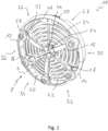
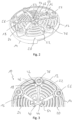
- the Figures 1 to 3 show a perspective view and an axial view of an exhaust gas heater, generally designated 10, for an exhaust system of an internal combustion engine.
- the exhaust gas heater 10 is used to transfer heat to this through flowing exhaust gas, in particular in a starting phase of the operation of an internal combustion engine downstream of the exhaust gas heater 10 arranged system areas such.
- the exhaust gas heater 10 includes a support assembly, generally designated 12 .
- the carrier arrangement 12 comprises a ring-like first carrier element 14 formed, for example, from sheet metal material, which preferably essentially completely surrounds a longitudinal axis L of the exhaust gas heater in the circumferential direction and can therefore have a closed ring structure, for example.
- the exhaust gas heater longitudinal axis L is essentially oriented in a main exhaust gas flow direction A, in which the exhaust gas emitted by an internal combustion engine flows towards the exhaust gas heater 10 .
- the support arrangement 12 further comprises a plurality of second support elements 16 designed as connecting arms and a plurality of second support elements 18 designed as connecting clamps.
- the second support elements 16, 18 are also made of sheet metal or metal material, for example, and are provided as components designed separately from the first support element 12 .
- a heating conductor arrangement is carried on the support arrangement 12.
- the two heating conductors 22, 24 have a plate-like structure that extends essentially orthogonally to the longitudinal axis L of the exhaust gas heater and are provided, for example, by being cut out of a metal material blank.
- the heating conductors 22, 24 arranged axially one after the other have a plurality of meander winding fields 26, 28, 30, 32, 34, 36 arranged one after the other in the circumferential direction on.
- the heating conductors 22, 24 have a plurality of meander winding sections which run essentially in the circumferential direction and are staggered radially with respect to one another.
- Meander winding fields 26, 28, 30, 32, 34, 36 immediately adjacent to one another in the circumferential direction are alternately connected to one another in a radially inner winding field connection region 40 or a radially outer winding field connection region 42 or close in this radially inner or radially outer Winding field connection areas 40, 42 to each other.
- the heating conductors 22, 24 with their meander winding sections are at an axial distance from one another, the heating conductors 22, 24 are shaped in such a way that in the radially inner winding field Connection areas 40 and the radially outer winding field connection areas 42, the heating conductors 22, 24 abut one another, in order to thereby provide radially inner coupling areas 44 connected to the coupling arrangement 12 or radially outer coupling areas 46 of the heating conductor arrangement 20, in which these are connected to the carrier arrangement 12 or the second carrier elements 16, 18 of the same is connected.
- the two heating conductors 22, 24 with their radially outermost meander winding sections provide respective contact elements 48, 50 in interconnected areas of the same, in which the heating conductor arrangement 20 is electrically connected to a voltage source via respective contact units can be conductively connected.
- the 4 shows in more detail a second carrier element 16 designed as a connecting arm.
- This second carrier element 16 or each second carrier element 16 designed as a connecting arm extends essentially in the radial direction and has a first connecting region 52 in its radially outer end region for connection to the first carrier element 14 of the carrier arrangement 12 ready.
- this second carrier element 16 formed from sheet metal, for example, and designed as a connecting arm, has a second connecting region 54 that is radially offset with respect to the first connecting region 52 and does not overlap with it in the radial direction or in the circumferential direction, in which it is fixed to a radially inner coupling region 44 of the heating conductor arrangement 20 connected is.
- This fixed connection is preferably made by material connection, i.e.
- first connecting element 56 designed essentially in the manner of a bolt.
- a flow shielding area 58 that protrudes radially inward and is dome-like in the upstream direction is formed on first support element 14, which essentially completely covers the associated first connection area 52 in the circumferential direction and in the radial direction and due to the fact that it is positioned on the upstream side with respect to the associated first connection region 52, shields it from the direct flow of exhaust gas.
- Each fastener 56 is formed with a bolt having a male shank 60, a head 62 and a nut 64 threaded onto the male shank 60.
- a ceramic material for example, is provided between each first connecting region 52 and the first support element 14 or a flow shielding region 58 provided thereon constructed, disk-like insulating element 66 arranged.
- an insulating element 68 made of ceramic material for example, is arranged between the first connecting region 52 and the head 62 of the associated connecting element 56 .
- each first connecting region 52 between the two insulating elements 66, 68 assigned to it is carried on the first carrier element 14 in a stable and electrically insulated manner by a respective connecting element 60.
- the flow shielding areas 58 also shield the insulating elements 66, 68 and essential areas of a respective connecting element 56 from the direct oncoming flow of exhaust gas, so that excessive thermal stress does not occur in this area and stable mechanical cohesion of the second carrier elements 16, which are designed as connecting arms, with the ring-like first carrier element 14 is guaranteed.
- Each second carrier element 18 designed as a connecting clamp has an essentially U-shaped structure with two U-legs 70, 72 and a connecting web 74 connecting them.
- one of the U-legs 70, 72 can be formed integrally with the connecting web 74 and can be connected to the other U-leg constructed as a separate component, in the exemplary embodiment shown the U-leg 70, for example by a material connection, such as e.g. B. welding or the like., Be firmly connected.
- a one-piece configuration of the second support elements 18, which are designed with a U-shaped structure, ie as connecting clamps, as sheet metal formed parts is also fundamentally possible.
- the U-leg 70 of the second carrier element 18 has its first connection region 76 in which the second connection element 18 designed as a connection clamp is connected to the first carrier element 14 by a connection element 78 designed, for example, like a bolt.
- This connecting element 78 is also constructed with an externally threaded shank 80 and a head 82 provided thereon and a nut 84 screwed onto the externally threaded shank 80 .
- An insulating element 86 is provided in the flow shielding area 58 .
- an insulating element 88 is provided between the first connecting region 76 and the head 82 of the connecting element 78 so that the first connecting region 76 is supported on the first carrier element 14 in a manner that is essentially shielded against the direct oncoming flow of exhaust gas.
- the second connecting region 90 of the second carrier element 18 designed as a connecting clamp, which is arranged in the same radial region as the first connecting region 76 and overlaps with it essentially completely radially and in the circumferential direction, engages behind the two heating conductors 22, 24 of the heating conductor arrangement 20 on their downstream-oriented side in one a radially outer coupling area 46 providing radially outer winding field connection area 42 and is firmly connected there to the two heat conductors 22, 24 by material connection, for example welding.
- the carrier arrangement 12 one after the other in the circumferential direction, has a second connecting element 16 designed as a connecting arm with first and second connecting regions 52, 54 that are radially offset from one another and do not overlap one another, and a second carrier element 18 designed as a connecting clamp with essentially no radially with respect to one another offset and overlapping first and second bond regions 76,90.
- This ensures alternating stable mounting of the heating conductor arrangement 20 in its radially outer area and in its radially inner area.
- the second support elements 16, which extend essentially radially and are designed as connecting arms are arranged in such a way that they are positioned or cover them on the upstream side of the heating conductor arrangement 20 .
- the second carrier elements 16, 18 are in direct thermal contact with the heating conductor arrangement 20 due to the material connection or direct connection without interposition of insulating elements, so that when the heating conductor arrangement 20 is heated by applying an electrical voltage to the contact elements 48, 50 the second carrier elements 16, 18 are also heated and heat can thus be transferred to the exhaust gas flowing around them.
- the present invention provides a simply structured exhaust gas heater that can be produced with few components, in which the heating conductors connected in parallel in the exemplary embodiment shown essentially have no length regions where exhaust gas cannot flow or cannot be used for heat transfer to exhaust gas. This increases the efficiency of heat transfer.
- the heating conductor arrangement is stably supported on the ring-like first supporting element by the various second supporting elements, whereby due to the types of connection provided in relation to the heating conductor arrangement and also in relation to the first supporting element, there is a risk that different thermal expansions will lead to a loss of holding stability. is largely excluded. This is particularly due to the fact that the insulating elements used for electrical insulation do not act between the second support elements and the heating conductor arrangement, but rather between the second support elements and the first support element and are therefore not directly heated by the heating cable.
- the heating conductor arrangement could also have only one such essentially plate-like heating conductor, which can be connected to the carrier arrangement, for example, in the manner shown in the figures.
- the circumferential sequence of second carrier elements designed as connecting arms and connecting clamps could be different than shown in the figures.
- the connection provided without intermediate storage of insulating elements second carrier elements to the heating conductor arrangement could alternatively or in addition to the material-locking connection described above, for example, by bolt-like connecting elements such. B. rivet bolts or the like., Take place.
Landscapes
- Engineering & Computer Science (AREA)
- Chemical & Material Sciences (AREA)
- Chemical Kinetics & Catalysis (AREA)
- Combustion & Propulsion (AREA)
- Mechanical Engineering (AREA)
- General Engineering & Computer Science (AREA)
- Health & Medical Sciences (AREA)
- Toxicology (AREA)
- Exhaust Gas After Treatment (AREA)
- Processes For Solid Components From Exhaust (AREA)
- Resistance Heating (AREA)
- Exhaust Silencers (AREA)
Applications Claiming Priority (1)
| Application Number | Priority Date | Filing Date | Title |
|---|---|---|---|
| DE102021122681.3A DE102021122681A1 (de) | 2021-09-02 | 2021-09-02 | Abgasheizer |
Publications (2)
| Publication Number | Publication Date |
|---|---|
| EP4144965A1 true EP4144965A1 (fr) | 2023-03-08 |
| EP4144965B1 EP4144965B1 (fr) | 2024-06-26 |
Family
ID=82786528
Family Applications (1)
| Application Number | Title | Priority Date | Filing Date |
|---|---|---|---|
| EP22188208.7A Active EP4144965B1 (fr) | 2021-09-02 | 2022-08-02 | Élément de chauffage de gaz d'échappement |
Country Status (6)
| Country | Link |
|---|---|
| US (1) | US12486791B2 (fr) |
| EP (1) | EP4144965B1 (fr) |
| JP (1) | JP7485734B2 (fr) |
| KR (1) | KR102890813B1 (fr) |
| CN (1) | CN115750047A (fr) |
| DE (1) | DE102021122681A1 (fr) |
Cited By (1)
| Publication number | Priority date | Publication date | Assignee | Title |
|---|---|---|---|---|
| WO2024105179A1 (fr) * | 2022-11-17 | 2024-05-23 | Vitesco Technologies GmbH | Structure de support pour une matrice chauffante |
Citations (3)
| Publication number | Priority date | Publication date | Assignee | Title |
|---|---|---|---|---|
| EP3825528A1 (fr) * | 2019-11-22 | 2021-05-26 | Eberspächer Exhaust Technology GmbH | Chaudière à gaz d'échappement |
| EP3964696A1 (fr) * | 2020-09-08 | 2022-03-09 | Purem GmbH | Chauffage de gaz d'échappement |
| EP4060169A1 (fr) * | 2021-03-15 | 2022-09-21 | Purem GmbH | Chaudière à gaz d'échappement |
Family Cites Families (26)
| Publication number | Priority date | Publication date | Assignee | Title |
|---|---|---|---|---|
| JPS58108217U (ja) * | 1982-01-19 | 1983-07-23 | トヨタ自動車株式会社 | 排気パテイキユレ−トトラツプ |
| JPS6078918U (ja) * | 1983-11-08 | 1985-06-01 | トヨタ自動車株式会社 | デイ−ゼルパテイキユレ−ト浄化装置 |
| US4671058A (en) * | 1983-11-21 | 1987-06-09 | Nippondenso Co., Ltd. | Heating device |
| US4548625A (en) | 1984-07-11 | 1985-10-22 | Toyota Jidosha Kabushiki Kaisha | Exhaust gas cleaning device for diesel engines |
| US4723973A (en) * | 1985-09-28 | 1988-02-09 | Nippondenso Co., Ltd. | Purifying apparatus of a particulate trap-type for collecting particulates in exhaust gas from an engine |
| US5053603A (en) * | 1989-03-30 | 1991-10-01 | Donaldson Company, Inc. | Electrical resistance heater |
| JP2531299Y2 (ja) * | 1990-11-19 | 1997-04-02 | 三菱自動車工業株式会社 | 排気ガス処理装置 |
| DE9113928U1 (de) | 1991-11-08 | 1992-07-09 | Emitec Gesellschaft für Emissionstechnologie mbH, 53797 Lohmar | Wabenkörper mit mehreren, gegeneinander abgestützten Scheiben |
| JPH06212948A (ja) * | 1993-01-20 | 1994-08-02 | Isuzu Ceramics Kenkyusho:Kk | ディーゼルパティキュレートフィルタ |
| DE19536853A1 (de) | 1995-10-02 | 1997-04-03 | Emitec Emissionstechnologie | Elektrisch beheizbarer, in Teilbereiche unterteilter Wabenkörper mit Verbindungsstegen |
| JP2001317340A (ja) | 2000-04-28 | 2001-11-16 | Hitachi Hometec Ltd | 発熱体ユニットのシース熱電対取付け装置 |
| JP2002295236A (ja) | 2001-03-30 | 2002-10-09 | Hitachi Hometec Ltd | 発熱体ユニット |
| JP2004076920A (ja) | 2002-08-22 | 2004-03-11 | Tgk Co Ltd | 差圧制御弁 |
| JP2006212948A (ja) | 2005-02-04 | 2006-08-17 | Seiko Epson Corp | 液体噴射ヘッドおよび液体噴射装置 |
| EP2935996B1 (fr) * | 2012-12-18 | 2019-03-20 | Watlow Electric Manufacturing Company | Appareil de chauffage de gaz d'échappement perfectionné et procédé de chauffage |
| DE102014115063A1 (de) | 2014-10-16 | 2016-04-21 | Continental Automotive Gmbh | Tragstruktur, Vorrichtung zur Behandlung von Abgasen und Verfahren zu deren Herstellung |
| WO2017151975A1 (fr) * | 2016-03-02 | 2017-09-08 | Watlow Electric Manufacturing Company | Éléments de chauffage à nu pour le chauffage d'écoulements de fluide |
| JP7091249B2 (ja) * | 2016-03-02 | 2022-06-27 | ワットロー・エレクトリック・マニュファクチャリング・カンパニー | ヒータ作動フローバイパス |
| FR3077330B1 (fr) * | 2018-02-01 | 2020-03-13 | Faurecia Systemes D'echappement | Organe de chauffage a manipulation facilitee pour dispositif de purification des gaz d'echappement d'un vehicule |
| FR3085428B1 (fr) | 2018-09-03 | 2021-06-25 | Faurecia Systemes Dechappement | Dispositif de chauffage de gaz d'echappement, notamment pour un moteur a combustion |
| FR3085429B1 (fr) * | 2018-09-03 | 2020-11-27 | Faurecia Systemes Dechappement | Dispositif perfectionne de chauffage de gaz d'echappement, notamment pour un vehicule automobile |
| DE102019107384A1 (de) * | 2019-03-22 | 2020-09-24 | Eberspächer Exhaust Technology GmbH & Co. KG | Abgasheizelement |
| DE102019121382A1 (de) | 2019-08-07 | 2021-02-11 | Faurecia Emissions Control Technologies, Germany Gmbh | Abgasbehandlungseinrichtung und Fahrzeug |
| DE102020110869A1 (de) * | 2020-04-22 | 2021-10-28 | Purem GmbH | Abgasheizer |
| DE102020123017A1 (de) * | 2020-09-03 | 2022-03-03 | Liebherr-Werk Nenzing Gmbh | Mobile Arbeitsmaschine zur Tiefgründung und Verfahren zum Ausrichten eines Werkzeugs einer solchen Arbeitsmaschine |
| DE102021109568A1 (de) | 2021-03-15 | 2022-09-15 | Purem GmbH | Abgasheizer |
-
2021
- 2021-09-02 DE DE102021122681.3A patent/DE102021122681A1/de active Pending
-
2022
- 2022-08-02 EP EP22188208.7A patent/EP4144965B1/fr active Active
- 2022-08-30 KR KR1020220109385A patent/KR102890813B1/ko active Active
- 2022-09-01 CN CN202211063702.5A patent/CN115750047A/zh active Pending
- 2022-09-01 JP JP2022139019A patent/JP7485734B2/ja active Active
- 2022-09-02 US US17/929,421 patent/US12486791B2/en active Active
Patent Citations (3)
| Publication number | Priority date | Publication date | Assignee | Title |
|---|---|---|---|---|
| EP3825528A1 (fr) * | 2019-11-22 | 2021-05-26 | Eberspächer Exhaust Technology GmbH | Chaudière à gaz d'échappement |
| EP3964696A1 (fr) * | 2020-09-08 | 2022-03-09 | Purem GmbH | Chauffage de gaz d'échappement |
| EP4060169A1 (fr) * | 2021-03-15 | 2022-09-21 | Purem GmbH | Chaudière à gaz d'échappement |
Cited By (1)
| Publication number | Priority date | Publication date | Assignee | Title |
|---|---|---|---|---|
| WO2024105179A1 (fr) * | 2022-11-17 | 2024-05-23 | Vitesco Technologies GmbH | Structure de support pour une matrice chauffante |
Also Published As
| Publication number | Publication date |
|---|---|
| KR102890813B1 (ko) | 2025-11-24 |
| KR20230034165A (ko) | 2023-03-09 |
| JP7485734B2 (ja) | 2024-05-16 |
| DE102021122681A1 (de) | 2023-03-02 |
| JP2023036558A (ja) | 2023-03-14 |
| EP4144965B1 (fr) | 2024-06-26 |
| US20230060154A1 (en) | 2023-03-02 |
| US12486791B2 (en) | 2025-12-02 |
| CN115750047A (zh) | 2023-03-07 |
Similar Documents
| Publication | Publication Date | Title |
|---|---|---|
| EP3964696B1 (fr) | Chauffage de gaz d'échappement | |
| EP2836687B1 (fr) | Connection électrique de plusieurs couches en tôle d'un corps en nid d'abeille et corps en nid d'abeille correspondant | |
| EP4370787B1 (fr) | Dispositif de chauffage d'un flux de gaz d'échappement | |
| EP3207229B1 (fr) | Structure porteur, dispositif pour le traitement de gaz d'échappement et son procédé de fabrication | |
| EP3904647B1 (fr) | Unité de raccordement pour un chauffage à gaz d'échappement | |
| EP3901433B1 (fr) | Chauffage de gaz d'échappement | |
| EP4047194B1 (fr) | Support pour un disque de chauffage électrique dans un dispositif de traitement ultérieur des gaz d'échappement | |
| EP2744990B1 (fr) | Dispositif de traitement de gaz d'échappement | |
| EP4060169A1 (fr) | Chaudière à gaz d'échappement | |
| DE102019121382A1 (de) | Abgasbehandlungseinrichtung und Fahrzeug | |
| EP4144965B1 (fr) | Élément de chauffage de gaz d'échappement | |
| EP4141230B1 (fr) | Chauffage pour gaz d'échappement | |
| EP4223991B1 (fr) | Dispositif de chauffage électrique de gaz d'échappement | |
| EP4141229B1 (fr) | Chauffage à gaz d'échappement et procédé de fabrication d'un chauffage à gaz d'échappement | |
| EP4174295B1 (fr) | Broche de raccordement | |
| DE102022111864B4 (de) | Heizvorrichtung | |
| EP3907383B1 (fr) | Dispositif de chauffage à gaz d'échappement pour une installation de gaz d'échappement d'un moteur à combustion interne | |
| WO1997013056A1 (fr) | Corps en nid d'abeilles chauffe electriquement, a structures renforcees de repartition de courant | |
| EP4144964A1 (fr) | Système d'échappement | |
| EP4198273B1 (fr) | Dispositif de chauffage de gaz d'échappement | |
| EP4286662B1 (fr) | Unité de raccordement | |
| EP4141228B1 (fr) | Chauffage de gaz d'échappement | |
| DE102022114107B4 (de) | Abgasheizer | |
| DE102022111865B4 (de) | Heizvorrichtung | |
| EP3956550A1 (fr) | Dispositif de traitement de gaz d'échappement et véhicule |
Legal Events
| Date | Code | Title | Description |
|---|---|---|---|
| PUAI | Public reference made under article 153(3) epc to a published international application that has entered the european phase |
Free format text: ORIGINAL CODE: 0009012 |
|
| STAA | Information on the status of an ep patent application or granted ep patent |
Free format text: STATUS: THE APPLICATION HAS BEEN PUBLISHED |
|
| AK | Designated contracting states |
Kind code of ref document: A1 Designated state(s): AL AT BE BG CH CY CZ DE DK EE ES FI FR GB GR HR HU IE IS IT LI LT LU LV MC MK MT NL NO PL PT RO RS SE SI SK SM TR |
|
| STAA | Information on the status of an ep patent application or granted ep patent |
Free format text: STATUS: REQUEST FOR EXAMINATION WAS MADE |
|
| 17P | Request for examination filed |
Effective date: 20230710 |
|
| RBV | Designated contracting states (corrected) |
Designated state(s): AL AT BE BG CH CY CZ DE DK EE ES FI FR GB GR HR HU IE IS IT LI LT LU LV MC MK MT NL NO PL PT RO RS SE SI SK SM TR |
|
| GRAP | Despatch of communication of intention to grant a patent |
Free format text: ORIGINAL CODE: EPIDOSNIGR1 |
|
| STAA | Information on the status of an ep patent application or granted ep patent |
Free format text: STATUS: GRANT OF PATENT IS INTENDED |
|
| INTG | Intention to grant announced |
Effective date: 20240416 |
|
| GRAS | Grant fee paid |
Free format text: ORIGINAL CODE: EPIDOSNIGR3 |
|
| GRAA | (expected) grant |
Free format text: ORIGINAL CODE: 0009210 |
|
| STAA | Information on the status of an ep patent application or granted ep patent |
Free format text: STATUS: THE PATENT HAS BEEN GRANTED |
|
| AK | Designated contracting states |
Kind code of ref document: B1 Designated state(s): AL AT BE BG CH CY CZ DE DK EE ES FI FR GB GR HR HU IE IS IT LI LT LU LV MC MK MT NL NO PL PT RO RS SE SI SK SM TR |
|
| REG | Reference to a national code |
Ref country code: GB Ref legal event code: FG4D Free format text: NOT ENGLISH |
|
| REG | Reference to a national code |
Ref country code: CH Ref legal event code: EP |
|
| REG | Reference to a national code |
Ref country code: DE Ref legal event code: R096 Ref document number: 502022001116 Country of ref document: DE |
|
| PG25 | Lapsed in a contracting state [announced via postgrant information from national office to epo] |
Ref country code: BG Free format text: LAPSE BECAUSE OF FAILURE TO SUBMIT A TRANSLATION OF THE DESCRIPTION OR TO PAY THE FEE WITHIN THE PRESCRIBED TIME-LIMIT Effective date: 20240626 |
|
| PG25 | Lapsed in a contracting state [announced via postgrant information from national office to epo] |
Ref country code: FI Free format text: LAPSE BECAUSE OF FAILURE TO SUBMIT A TRANSLATION OF THE DESCRIPTION OR TO PAY THE FEE WITHIN THE PRESCRIBED TIME-LIMIT Effective date: 20240626 Ref country code: HR Free format text: LAPSE BECAUSE OF FAILURE TO SUBMIT A TRANSLATION OF THE DESCRIPTION OR TO PAY THE FEE WITHIN THE PRESCRIBED TIME-LIMIT Effective date: 20240626 |
|
| REG | Reference to a national code |
Ref country code: LT Ref legal event code: MG9D |
|
| PG25 | Lapsed in a contracting state [announced via postgrant information from national office to epo] |
Ref country code: GR Free format text: LAPSE BECAUSE OF FAILURE TO SUBMIT A TRANSLATION OF THE DESCRIPTION OR TO PAY THE FEE WITHIN THE PRESCRIBED TIME-LIMIT Effective date: 20240927 |
|
| PG25 | Lapsed in a contracting state [announced via postgrant information from national office to epo] |
Ref country code: LV Free format text: LAPSE BECAUSE OF FAILURE TO SUBMIT A TRANSLATION OF THE DESCRIPTION OR TO PAY THE FEE WITHIN THE PRESCRIBED TIME-LIMIT Effective date: 20240626 |
|
| REG | Reference to a national code |
Ref country code: NL Ref legal event code: MP Effective date: 20240626 |
|
| PG25 | Lapsed in a contracting state [announced via postgrant information from national office to epo] |
Ref country code: NO Free format text: LAPSE BECAUSE OF FAILURE TO SUBMIT A TRANSLATION OF THE DESCRIPTION OR TO PAY THE FEE WITHIN THE PRESCRIBED TIME-LIMIT Effective date: 20240926 Ref country code: LV Free format text: LAPSE BECAUSE OF FAILURE TO SUBMIT A TRANSLATION OF THE DESCRIPTION OR TO PAY THE FEE WITHIN THE PRESCRIBED TIME-LIMIT Effective date: 20240626 Ref country code: HR Free format text: LAPSE BECAUSE OF FAILURE TO SUBMIT A TRANSLATION OF THE DESCRIPTION OR TO PAY THE FEE WITHIN THE PRESCRIBED TIME-LIMIT Effective date: 20240626 Ref country code: GR Free format text: LAPSE BECAUSE OF FAILURE TO SUBMIT A TRANSLATION OF THE DESCRIPTION OR TO PAY THE FEE WITHIN THE PRESCRIBED TIME-LIMIT Effective date: 20240927 Ref country code: FI Free format text: LAPSE BECAUSE OF FAILURE TO SUBMIT A TRANSLATION OF THE DESCRIPTION OR TO PAY THE FEE WITHIN THE PRESCRIBED TIME-LIMIT Effective date: 20240626 Ref country code: BG Free format text: LAPSE BECAUSE OF FAILURE TO SUBMIT A TRANSLATION OF THE DESCRIPTION OR TO PAY THE FEE WITHIN THE PRESCRIBED TIME-LIMIT Effective date: 20240626 Ref country code: RS Free format text: LAPSE BECAUSE OF FAILURE TO SUBMIT A TRANSLATION OF THE DESCRIPTION OR TO PAY THE FEE WITHIN THE PRESCRIBED TIME-LIMIT Effective date: 20240926 |
|
| PG25 | Lapsed in a contracting state [announced via postgrant information from national office to epo] |
Ref country code: NL Free format text: LAPSE BECAUSE OF FAILURE TO SUBMIT A TRANSLATION OF THE DESCRIPTION OR TO PAY THE FEE WITHIN THE PRESCRIBED TIME-LIMIT Effective date: 20240626 |
|
| PG25 | Lapsed in a contracting state [announced via postgrant information from national office to epo] |
Ref country code: NL Free format text: LAPSE BECAUSE OF FAILURE TO SUBMIT A TRANSLATION OF THE DESCRIPTION OR TO PAY THE FEE WITHIN THE PRESCRIBED TIME-LIMIT Effective date: 20240626 |
|
| PG25 | Lapsed in a contracting state [announced via postgrant information from national office to epo] |
Ref country code: PT Free format text: LAPSE BECAUSE OF FAILURE TO SUBMIT A TRANSLATION OF THE DESCRIPTION OR TO PAY THE FEE WITHIN THE PRESCRIBED TIME-LIMIT Effective date: 20241028 |
|
| PG25 | Lapsed in a contracting state [announced via postgrant information from national office to epo] |
Ref country code: PT Free format text: LAPSE BECAUSE OF FAILURE TO SUBMIT A TRANSLATION OF THE DESCRIPTION OR TO PAY THE FEE WITHIN THE PRESCRIBED TIME-LIMIT Effective date: 20241028 |
|
| PG25 | Lapsed in a contracting state [announced via postgrant information from national office to epo] |
Ref country code: PL Free format text: LAPSE BECAUSE OF FAILURE TO SUBMIT A TRANSLATION OF THE DESCRIPTION OR TO PAY THE FEE WITHIN THE PRESCRIBED TIME-LIMIT Effective date: 20240626 |
|
| PG25 | Lapsed in a contracting state [announced via postgrant information from national office to epo] |
Ref country code: EE Free format text: LAPSE BECAUSE OF FAILURE TO SUBMIT A TRANSLATION OF THE DESCRIPTION OR TO PAY THE FEE WITHIN THE PRESCRIBED TIME-LIMIT Effective date: 20240626 |
|
| PG25 | Lapsed in a contracting state [announced via postgrant information from national office to epo] |
Ref country code: IS Free format text: LAPSE BECAUSE OF FAILURE TO SUBMIT A TRANSLATION OF THE DESCRIPTION OR TO PAY THE FEE WITHIN THE PRESCRIBED TIME-LIMIT Effective date: 20241026 |
|
| PG25 | Lapsed in a contracting state [announced via postgrant information from national office to epo] |
Ref country code: CZ Free format text: LAPSE BECAUSE OF FAILURE TO SUBMIT A TRANSLATION OF THE DESCRIPTION OR TO PAY THE FEE WITHIN THE PRESCRIBED TIME-LIMIT Effective date: 20240626 |
|
| PG25 | Lapsed in a contracting state [announced via postgrant information from national office to epo] |
Ref country code: RO Free format text: LAPSE BECAUSE OF FAILURE TO SUBMIT A TRANSLATION OF THE DESCRIPTION OR TO PAY THE FEE WITHIN THE PRESCRIBED TIME-LIMIT Effective date: 20240626 Ref country code: SK Free format text: LAPSE BECAUSE OF FAILURE TO SUBMIT A TRANSLATION OF THE DESCRIPTION OR TO PAY THE FEE WITHIN THE PRESCRIBED TIME-LIMIT Effective date: 20240626 |
|
| PG25 | Lapsed in a contracting state [announced via postgrant information from national office to epo] |
Ref country code: SM Free format text: LAPSE BECAUSE OF FAILURE TO SUBMIT A TRANSLATION OF THE DESCRIPTION OR TO PAY THE FEE WITHIN THE PRESCRIBED TIME-LIMIT Effective date: 20240626 Ref country code: ES Free format text: LAPSE BECAUSE OF FAILURE TO SUBMIT A TRANSLATION OF THE DESCRIPTION OR TO PAY THE FEE WITHIN THE PRESCRIBED TIME-LIMIT Effective date: 20240626 |
|
| PG25 | Lapsed in a contracting state [announced via postgrant information from national office to epo] |
Ref country code: SM Free format text: LAPSE BECAUSE OF FAILURE TO SUBMIT A TRANSLATION OF THE DESCRIPTION OR TO PAY THE FEE WITHIN THE PRESCRIBED TIME-LIMIT Effective date: 20240626 Ref country code: SK Free format text: LAPSE BECAUSE OF FAILURE TO SUBMIT A TRANSLATION OF THE DESCRIPTION OR TO PAY THE FEE WITHIN THE PRESCRIBED TIME-LIMIT Effective date: 20240626 Ref country code: RO Free format text: LAPSE BECAUSE OF FAILURE TO SUBMIT A TRANSLATION OF THE DESCRIPTION OR TO PAY THE FEE WITHIN THE PRESCRIBED TIME-LIMIT Effective date: 20240626 Ref country code: PL Free format text: LAPSE BECAUSE OF FAILURE TO SUBMIT A TRANSLATION OF THE DESCRIPTION OR TO PAY THE FEE WITHIN THE PRESCRIBED TIME-LIMIT Effective date: 20240626 Ref country code: IS Free format text: LAPSE BECAUSE OF FAILURE TO SUBMIT A TRANSLATION OF THE DESCRIPTION OR TO PAY THE FEE WITHIN THE PRESCRIBED TIME-LIMIT Effective date: 20241026 Ref country code: ES Free format text: LAPSE BECAUSE OF FAILURE TO SUBMIT A TRANSLATION OF THE DESCRIPTION OR TO PAY THE FEE WITHIN THE PRESCRIBED TIME-LIMIT Effective date: 20240626 Ref country code: EE Free format text: LAPSE BECAUSE OF FAILURE TO SUBMIT A TRANSLATION OF THE DESCRIPTION OR TO PAY THE FEE WITHIN THE PRESCRIBED TIME-LIMIT Effective date: 20240626 Ref country code: CZ Free format text: LAPSE BECAUSE OF FAILURE TO SUBMIT A TRANSLATION OF THE DESCRIPTION OR TO PAY THE FEE WITHIN THE PRESCRIBED TIME-LIMIT Effective date: 20240626 |
|
| PG25 | Lapsed in a contracting state [announced via postgrant information from national office to epo] |
Ref country code: IT Free format text: LAPSE BECAUSE OF FAILURE TO SUBMIT A TRANSLATION OF THE DESCRIPTION OR TO PAY THE FEE WITHIN THE PRESCRIBED TIME-LIMIT Effective date: 20240626 |
|
| REG | Reference to a national code |
Ref country code: DE Ref legal event code: R026 Ref document number: 502022001116 Country of ref document: DE |
|
| PLBI | Opposition filed |
Free format text: ORIGINAL CODE: 0009260 |
|
| PLAX | Notice of opposition and request to file observation + time limit sent |
Free format text: ORIGINAL CODE: EPIDOSNOBS2 |
|
| PG25 | Lapsed in a contracting state [announced via postgrant information from national office to epo] |
Ref country code: DK Free format text: LAPSE BECAUSE OF FAILURE TO SUBMIT A TRANSLATION OF THE DESCRIPTION OR TO PAY THE FEE WITHIN THE PRESCRIBED TIME-LIMIT Effective date: 20240626 |
|
| PG25 | Lapsed in a contracting state [announced via postgrant information from national office to epo] |
Ref country code: LU Free format text: LAPSE BECAUSE OF NON-PAYMENT OF DUE FEES Effective date: 20240802 |
|
| PG25 | Lapsed in a contracting state [announced via postgrant information from national office to epo] |
Ref country code: MC Free format text: LAPSE BECAUSE OF FAILURE TO SUBMIT A TRANSLATION OF THE DESCRIPTION OR TO PAY THE FEE WITHIN THE PRESCRIBED TIME-LIMIT Effective date: 20240626 |
|
| 26 | Opposition filed |
Opponent name: EMITEC TECHNOLOGIES GMBH Effective date: 20250321 |
|
| REG | Reference to a national code |
Ref country code: BE Ref legal event code: MM Effective date: 20240831 |
|
| PLBB | Reply of patent proprietor to notice(s) of opposition received |
Free format text: ORIGINAL CODE: EPIDOSNOBS3 |
|
| PG25 | Lapsed in a contracting state [announced via postgrant information from national office to epo] |
Ref country code: BE Free format text: LAPSE BECAUSE OF NON-PAYMENT OF DUE FEES Effective date: 20240831 |
|
| PG25 | Lapsed in a contracting state [announced via postgrant information from national office to epo] |
Ref country code: IE Free format text: LAPSE BECAUSE OF NON-PAYMENT OF DUE FEES Effective date: 20240802 |
|
| PLAY | Examination report in opposition despatched + time limit |
Free format text: ORIGINAL CODE: EPIDOSNORE2 |
|
| PG25 | Lapsed in a contracting state [announced via postgrant information from national office to epo] |
Ref country code: SE Free format text: LAPSE BECAUSE OF FAILURE TO SUBMIT A TRANSLATION OF THE DESCRIPTION OR TO PAY THE FEE WITHIN THE PRESCRIBED TIME-LIMIT Effective date: 20240626 |
|
| PGFP | Annual fee paid to national office [announced via postgrant information from national office to epo] |
Ref country code: DE Payment date: 20250819 Year of fee payment: 4 |
|
| PGFP | Annual fee paid to national office [announced via postgrant information from national office to epo] |
Ref country code: FR Payment date: 20250821 Year of fee payment: 4 Ref country code: AT Payment date: 20251020 Year of fee payment: 4 |
|
| PG25 | Lapsed in a contracting state [announced via postgrant information from national office to epo] |
Ref country code: CY Free format text: LAPSE BECAUSE OF FAILURE TO SUBMIT A TRANSLATION OF THE DESCRIPTION OR TO PAY THE FEE WITHIN THE PRESCRIBED TIME-LIMIT; INVALID AB INITIO Effective date: 20220802 |
|
| PG25 | Lapsed in a contracting state [announced via postgrant information from national office to epo] |
Ref country code: HU Free format text: LAPSE BECAUSE OF FAILURE TO SUBMIT A TRANSLATION OF THE DESCRIPTION OR TO PAY THE FEE WITHIN THE PRESCRIBED TIME-LIMIT; INVALID AB INITIO Effective date: 20220802 |
|
| REG | Reference to a national code |
Ref country code: CH Ref legal event code: H13 Free format text: ST27 STATUS EVENT CODE: U-0-0-H10-H13 (AS PROVIDED BY THE NATIONAL OFFICE) Effective date: 20260324 |
|
| PG25 | Lapsed in a contracting state [announced via postgrant information from national office to epo] |
Ref country code: CH Free format text: LAPSE BECAUSE OF NON-PAYMENT OF DUE FEES Effective date: 20250831 |