EP4144982A1 - Verfahren und system um kraftstoffdampfleck in einer brennkraftmaschine zu detektieren - Google Patents
Verfahren und system um kraftstoffdampfleck in einer brennkraftmaschine zu detektieren Download PDFInfo
- Publication number
- EP4144982A1 EP4144982A1 EP22193365.8A EP22193365A EP4144982A1 EP 4144982 A1 EP4144982 A1 EP 4144982A1 EP 22193365 A EP22193365 A EP 22193365A EP 4144982 A1 EP4144982 A1 EP 4144982A1
- Authority
- EP
- European Patent Office
- Prior art keywords
- purge
- downstream
- richness
- circuit
- exhaust
- Prior art date
- Legal status (The legal status is an assumption and is not a legal conclusion. Google has not performed a legal analysis and makes no representation as to the accuracy of the status listed.)
- Granted
Links
Images
Classifications
-
- F—MECHANICAL ENGINEERING; LIGHTING; HEATING; WEAPONS; BLASTING
- F02—COMBUSTION ENGINES; HOT-GAS OR COMBUSTION-PRODUCT ENGINE PLANTS
- F02M—SUPPLYING COMBUSTION ENGINES IN GENERAL WITH COMBUSTIBLE MIXTURES OR CONSTITUENTS THEREOF
- F02M25/00—Engine-pertinent apparatus for adding non-fuel substances or small quantities of secondary fuel to combustion-air, main fuel or fuel-air mixture
- F02M25/08—Engine-pertinent apparatus for adding non-fuel substances or small quantities of secondary fuel to combustion-air, main fuel or fuel-air mixture adding fuel vapours drawn from engine fuel reservoir
- F02M25/0809—Judging failure of purge control system
-
- F—MECHANICAL ENGINEERING; LIGHTING; HEATING; WEAPONS; BLASTING
- F02—COMBUSTION ENGINES; HOT-GAS OR COMBUSTION-PRODUCT ENGINE PLANTS
- F02M—SUPPLYING COMBUSTION ENGINES IN GENERAL WITH COMBUSTIBLE MIXTURES OR CONSTITUENTS THEREOF
- F02M25/00—Engine-pertinent apparatus for adding non-fuel substances or small quantities of secondary fuel to combustion-air, main fuel or fuel-air mixture
- F02M25/08—Engine-pertinent apparatus for adding non-fuel substances or small quantities of secondary fuel to combustion-air, main fuel or fuel-air mixture adding fuel vapours drawn from engine fuel reservoir
- F02M25/0809—Judging failure of purge control system
- F02M25/0827—Judging failure of purge control system by monitoring engine running conditions
-
- F—MECHANICAL ENGINEERING; LIGHTING; HEATING; WEAPONS; BLASTING
- F02—COMBUSTION ENGINES; HOT-GAS OR COMBUSTION-PRODUCT ENGINE PLANTS
- F02M—SUPPLYING COMBUSTION ENGINES IN GENERAL WITH COMBUSTIBLE MIXTURES OR CONSTITUENTS THEREOF
- F02M25/00—Engine-pertinent apparatus for adding non-fuel substances or small quantities of secondary fuel to combustion-air, main fuel or fuel-air mixture
- F02M25/08—Engine-pertinent apparatus for adding non-fuel substances or small quantities of secondary fuel to combustion-air, main fuel or fuel-air mixture adding fuel vapours drawn from engine fuel reservoir
- F02M25/0836—Arrangement of valves controlling the admission of fuel vapour to an engine, e.g. valve being disposed between fuel tank or absorption canister and intake manifold
-
- F—MECHANICAL ENGINEERING; LIGHTING; HEATING; WEAPONS; BLASTING
- F02—COMBUSTION ENGINES; HOT-GAS OR COMBUSTION-PRODUCT ENGINE PLANTS
- F02M—SUPPLYING COMBUSTION ENGINES IN GENERAL WITH COMBUSTIBLE MIXTURES OR CONSTITUENTS THEREOF
- F02M25/00—Engine-pertinent apparatus for adding non-fuel substances or small quantities of secondary fuel to combustion-air, main fuel or fuel-air mixture
- F02M25/08—Engine-pertinent apparatus for adding non-fuel substances or small quantities of secondary fuel to combustion-air, main fuel or fuel-air mixture adding fuel vapours drawn from engine fuel reservoir
- F02M25/089—Layout of the fuel vapour installation
Definitions
- the present invention relates to the field of internal combustion engines, and more particularly to the detection of a leak of fuel vapours, in particular gasoline.
- Motor vehicles equipped with a spark-ignition engine are equipped with a fuel vapor tank, known to those skilled in the art by its English name “canister”, comprising a carbon filter and configured to accumulate fuel vapors escaping from the fuel tank when the vehicle is stationary or the vehicle is operating under severe conditions.
- a fuel vapor tank known to those skilled in the art by its English name “canister” comprising a carbon filter and configured to accumulate fuel vapors escaping from the fuel tank when the vehicle is stationary or the vehicle is operating under severe conditions.
- the depression in the intake manifold located downstream of the engine's throttle body is used to draw in the fuel vapors stored in the canister.
- the engine draws in the fuel vapors contained in the canister in order to burn them in the combustion chambers of the engine with the fuel coming from the engine's fuel injectors. This suction is generally achieved by depression of the intake manifold.
- the purge pump is connected by an upstream pipe to the canister, and by a downstream pipe to a purge solenoid valve.
- purge solenoid valve is connected to the engine intake, downstream of the throttle body, by yet another connecting pipe.
- the method includes a step in which the purge pump is operated, which results in a flow of vapors which follows a known profile passing through a predetermined maximum value and which drops to zero when the purge valve is closed.
- the object of the present invention is therefore to provide a method and a system for detecting fuel vapor leaks, in particular between the pump and the engine intake, capable of detecting a leak in a non-intrusive manner, i.e. that is to say without disturbing the normal operation of the engine, and without adding any additional component.
- the subject of the invention is a method for detecting a fuel vapor leak in a purge circuit of an internal combustion engine comprising a fresh air intake manifold comprising a flow meter configured to measure the flow of fresh air entering said manifold, an exhaust manifold and a depollution system comprising at least a first depollution device and at least a first richness sensor upstream of the first depollution device, the engine further comprising a purge circuit comprising a fuel vapor tank connected to a fuel tank fuel, a bleed pump connected downstream of the vapor tank and a bleed valve connected downstream of the pump and opening into the air intake duct downstream of the flow meter.
- the method for detecting a leak is thus configured to establish a non-intrusive diagnosis making it possible to have a presumption of a leak in the pipes between the pump and the intake of the engine
- an alert is issued on the dashboard of the vehicle.
- the invention relates to a system for detecting a fuel vapor leak in a purge circuit of an internal combustion engine comprising a fresh air intake manifold comprising a flow meter configured to measure the flow of fresh air entering said manifold, an exhaust manifold and a depollution system comprising at least a first depollution device and at least a first richness sensor upstream of the first depollution device, the engine further comprising a purge circuit comprising a fuel vapor tank connected to a fuel tank, a purge pump connected downstream of the vapor tank and a purge valve connected downstream of the pump and opening into the air intake duct downstream of the flowmeter.
- the detection system comprises a module for comparing the real richness value with a threshold value and a control module for closing the purge valve when the real richness is lower than the threshold value, if, after closing the purge valve, the actual richness is greater than or equal to the threshold value, the detection system is configured to conclude that there is a leak on the purge system.
- the detection system is configured to emit an alert on the dashboard of the vehicle.
- the invention further relates to a powertrain comprising a fresh air intake manifold comprising a flow meter configured to measure the flow of fresh air entering said manifold, an exhaust manifold and a pollution control system comprising at least one first pollution control device and at least one first richness sensor upstream of the first pollution control device, the engine further comprising a purge circuit comprising a fuel vapor tank connected to a fuel tank, a purge pump connected downstream vapor tank and a purge valve connected downstream of the pump and opening into the air intake duct downstream of the flowmeter, and a leak detection system as described previously.
- the invention relates to a motor vehicle comprising a powertrain as described above.
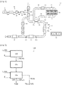
- FIG. 1 there is shown, schematically, the general structure of an internal combustion engine 10, in particular of the spark-ignition type operating on gasoline, of a motor vehicle.
- the internal combustion engine 10 comprises, without limitation, three cylinders 12 in line, a fresh air intake manifold 14, an exhaust manifold 16 and a turbo-compression system 18 .
- the cylinders 12 are supplied with air via the intake manifold 14, or intake distributor, itself supplied by a pipe 20 provided with an air filter 22 and the compressor 18b of the turbocharger 18 of the engine 10 .
- the turbocharger 18 essentially comprises a turbine 18a driven by the exhaust gases and a compressor 18b mounted on the same axis or shaft as the turbine 18a and providing compression of the air distributed by the air filter 22, in order to increase the quantity (mass flow) of air admitted into the cylinders 12 of the engine 10.
- the turbine 18a can be of the "variable geometry" type, that is to say that the wheel of the turbine is fitted with variable-angle fins in order to modulate the amount of energy taken from the exhaust gases, and thus the boost pressure.
- a heat exchanger 24 is placed after the outlet of the compressor 18b equipping the supply line 14a of the intake manifold 14 with fresh air.
- the internal combustion engine 10 thus comprises an intake circuit Ca and an exhaust circuit Ce.
- the latter recovers the exhaust gases resulting from combustion and evacuates them to the outside, via a gas exhaust duct 34 leading to the turbine 18a of turbocharger 18 and by an exhaust line 36 mounted downstream of said turbine 18a.
- the engine 10 comprises a partial recirculation circuit 38 of the exhaust gases at the intake, called “EGR” circuit (“exhaust gas recirculation” in Anglo-Saxon terms).
- EGR exhaust gas recirculation circuit
- This circuit 38 here a low pressure exhaust gas recirculation circuit, called "EGR BP"
- EGR BP a low pressure exhaust gas recirculation circuit
- This circuit 38 originates at a point on the exhaust line 36, downstream of said turbine 18a, and in particular downstream of the system 40 for gas pollution control and returns the exhaust gases to a point in the fresh air supply pipe 20, upstream of the compressor 18b of the turbocharger 18, in particular downstream of the flow meter 26.
- the flow meter 26 only measures the flow fresh air alone.
- this recirculation circuit 38 comprises, in the direction of circulation of the recycled gases, a cooler 38a, a filter 38b, and a "V EGR BP" valve 38c configured to regulate the flow of exhaust gases at low pressure.
- the "V EGR BP" valve 38c is arranged downstream of the cooler 38a and upstream of the compressor 18b.
- the engine combustion gas pollution control system 40 comprises a first device 42 comprising two electrically heated three-way catalysts 42a, 42b in series, with at least one first oxygen sensor 43a, of the proportional type , mounted upstream of the first depollution device 42, that is to say upstream of said catalysts 42a, 42b.
- the first upstream oxygen sensor 43a is generally used to regulate in a closed loop the value of the richness of the air-fuel mixture in the engine around a setpoint value, for example the value 1 corresponding to a mixture air-fuel in stoichiometric proportions.
- a second oxygen sensor 43b for example of the binary or proportional type, is most frequently mounted downstream of the first depollution device so as to be able to correct said set point value of the aforementioned richness regulation loop, in particular in the purpose of adjusting the amount of oxygen stored at inside the first depollution device 42.
- this second downstream probe is not essential to the realization of the invention.
- the gas pollution control system 40 further comprises a second device 44 which is here a fine particle filter, and a third device 46 which is here a three-way catalyst. It may also include a third oxygen sensor 43c, for example of the binary type, mounted downstream of the second device 44, for diagnostic purposes for example.
- the engine is associated with a fuel circuit comprising, for example, fuel injectors (not referenced) injecting gasoline directly into each cylinder from a fuel tank 50 .
- the engine also includes a fuel vapor purge circuit 60 comprising a canister 62 or fuel vapor tank 62 receiving fuel vapors from the fuel tank 50 via a first pipe 60a, an active pump 64 connected by a second pipe 60b downstream of the canister 62 and a purge solenoid valve 66 connected by a third pipe 60c downstream of the pump 64.
- the purge solenoid valve 66 is connected to the engine intake, downstream of the flow meter 26 by a fourth pipe 60d.
- the engine comprises an electronic control unit 70 configured to control the various elements of the internal combustion engine from data collected by sensors at various locations of the engine.
- the engine speed-load operating point is adjusted by the engine computer 70 by adjusting in particular a quantity of air, a quantity of EGR recirculation gases BP, and a quantity of fuel.
- quantity is meant here a mass flow rate.
- the air flow and the flow of recirculation gas EGR BP can be set to set values by the engine computer 70 by adjusting on the one hand the position of the throttle body 30 and the boost pressure of the turbocharger 18, who commands the total gas flow in the engine, and on the other hand that of the "V EGR BP" valve 38c of the recirculation circuit 38.
- the fuel flow rate is regulated by the engine computer 70 so as to adjust the richness of the air-fuel mixture admitted into the cylinders of the engine to a setpoint value ⁇ _cons, for example a richness value equal to 1 corresponding to the stoichiometric proportions of the air-fuel mixture.
- a setpoint value ⁇ _cons for example a richness value equal to 1 corresponding to the stoichiometric proportions of the air-fuel mixture.
- a regulator not represented of the PID type
- the fuel flow comes from two possible sources: on the one hand from a flow injected by the injectors Q_carb_inj, which is regulated by the computer 70 of the engine via the adjustment of a duration of opening of the injectors, and from on the other hand, in the event of purging of the fuel vapours, of the flow of fuel coming from the purge circuit 60 when the active pump 64 is started up and the purge solenoid valve 66 is open.
- the engine computer 70 comprises a module 72 for calculating the quantity (mass flow) of fuel Q_carb_inj to be injected by the injectors.
- the quantity of fuel to be injected by the injectors is calculated as the sum on the one hand, of a quantity calculated in open loop corresponding to the difference between the total quantity of fuel A to be introduced to produce the torque T minus the quantity of fuel B present at the outlet of the pump 64 and which is normally supposed to be sent entirely to the intake, and, on the other hand, by a corrective term C of closed-loop adjustment.
- the quantity calculated in open loop is normally precise enough for the corrective term C to only be used to compensate for low engine variability (manufacturing tolerances, etc.), so that the value of the real richness ⁇ _mes measured by the first richness probe 43a deviates only very slightly from an expected value which is the set value.
- the value of the measured richness is lower by at least ten percent than the expected value, there is a failure in the fuel supply system taken as a whole.
- it may be a priori either a problem with a clogged injector, which prevents the injection of the required quantity of fuel despite the increase in the opening time of the injectors, or a problem of leak in the purge circuit pipes mounted downstream of the pump 64, part of the fuel flow leaving the pump 64, which is used to calculate the second quantity B, not actually reaching the engine intake.
- the invention succeeds in diagnosing more specifically the presence of a leak or of a disconnection of the pipes mounted downstream of the pump 64.
- the engine computer 70 further comprises a module 74 for detecting a fuel vapor leak between the purge pump 64 and the intake.
- the module 74 for detecting a fuel vapor leak comprises a module for comparing the real richness ⁇ _mes obtained via the first proportional richness probe 43a upstream of the first depollution device 42 with a threshold value S.
- the value of threshold corresponds to the expected richness (setpoint richness) reduced by a predetermined margin.
- the margin is equal to ten percent of the set value.
- the threshold S is for example equal to 0.9.
- the real richness ⁇ _mes undergoes a significant drift compared to the expected richness, in other words if it is lower than the threshold value S, it can be estimated that there is a failure in the fuel injection system including the injectors, or on the amount of fuel that comes from the purge system 60.
- the module 74 for detecting a leak of fuel vapors comprises a module for determining a setpoint for closing the purge valve 66 when the real richness ⁇ _mes is lower than the threshold value S corresponding to this significant deviation from to the expected wealth.
- the real richness ⁇ _mes measured by the first proportional probe 43a is again compared with the threshold value S.
- a leak on at least one of said pipes has the consequence that at least part of the flow of fuel leaving the pump 64 does not reach the intake of the engine. Therefore, in assimilating the second quantity of fuel B to the flow from the pump, this second quantity B of fuel supposedly admitted into the engine is overestimated, and the quantity of fuel AB to be injected in an open loop by the injectors is therefore underestimated, so that, before the closed loop can cause the richness to converge on its setpoint value, measured values are observed that are markedly lower than the setpoint.
- the purge setpoint is set to zero, that is to say that the value of the second quantity B of fuel becomes equal to zero.
- the quantity of fuel delivered by the injectors is then instantaneously calculated as the sum of a prepositioning corresponding to the first quantity of fuel A alone and of the closed loop corrective term C.
- the richness returns to an expected value (i.e. becomes greater than or equal to the threshold value S), i.e. it approaches the setpoint value, then we can have the presumption that there is has a problem with the purge circuit failing, because it had previously been revealed that there was a lack of richness control on a purge phase due to fuel vapors which did not reach the engine intake.
- a fuel vapor leak is thus detected differentially by the detection module 74 on the purge system 60 in a non-intrusive manner.
- the method 100 for detecting a fuel vapor leak between the purge pump 64 and the intake comprises a step 102 of comparing the real richness ⁇ _mes from the first probe proportional 43a upstream of the first depollution device 42 with a threshold value S.
- the purge valve 66 is closed in step 104 and after closing the valve, a comparison is made again, in step 106 , the real richness ⁇ _mes measured by the first proportional probe 43a with the threshold value S.
- the leak may come from another location in the fuel injection system, which must then be analyzed in detail to determine whether it is a problem with the injection pump, injector, piping, etc.
Landscapes
- Engineering & Computer Science (AREA)
- Chemical & Material Sciences (AREA)
- Combustion & Propulsion (AREA)
- Mechanical Engineering (AREA)
- General Engineering & Computer Science (AREA)
- Supplying Secondary Fuel Or The Like To Fuel, Air Or Fuel-Air Mixtures (AREA)
Applications Claiming Priority (1)
| Application Number | Priority Date | Filing Date | Title |
|---|---|---|---|
| FR2109298A FR3126735B1 (fr) | 2021-09-06 | 2021-09-06 | Procédé et système de détection d’une fuite de vapeurs de carburant dans un moteur à combustion interne |
Publications (2)
| Publication Number | Publication Date |
|---|---|
| EP4144982A1 true EP4144982A1 (de) | 2023-03-08 |
| EP4144982B1 EP4144982B1 (de) | 2025-06-04 |
Family
ID=78536362
Family Applications (1)
| Application Number | Title | Priority Date | Filing Date |
|---|---|---|---|
| EP22193365.8A Active EP4144982B1 (de) | 2021-09-06 | 2022-09-01 | Verfahren um kraftstoffdampfleck in einer brennkraftmaschine zu detektieren |
Country Status (2)
| Country | Link |
|---|---|
| EP (1) | EP4144982B1 (de) |
| FR (1) | FR3126735B1 (de) |
Citations (4)
| Publication number | Priority date | Publication date | Assignee | Title |
|---|---|---|---|---|
| EP0682745B1 (de) | 1993-02-03 | 1998-06-17 | Siemens Canada Limited | Integritätsbestätigung eines knistersystems mit positivem druck |
| EP2201235B1 (de) * | 2007-09-14 | 2013-04-03 | Robert Bosch GmbH | Verfahren und vorrichtung zum steuern einer brennkraftmaschine |
| FR3027956A1 (fr) | 2014-10-31 | 2016-05-06 | Renault Sa | Procede de diagnostic du fonctionnement de la purge d'un canister |
| US20170314512A1 (en) * | 2016-04-29 | 2017-11-02 | Ford Global Technologies, Llc | Fuel vapor purging diagnostics for a multi-path purge ejector system |
Family Cites Families (1)
| Publication number | Priority date | Publication date | Assignee | Title |
|---|---|---|---|---|
| JP2020105958A (ja) * | 2018-12-27 | 2020-07-09 | 愛三工業株式会社 | 蒸発燃料処理装置の漏れ診断装置 |
-
2021
- 2021-09-06 FR FR2109298A patent/FR3126735B1/fr active Active
-
2022
- 2022-09-01 EP EP22193365.8A patent/EP4144982B1/de active Active
Patent Citations (4)
| Publication number | Priority date | Publication date | Assignee | Title |
|---|---|---|---|---|
| EP0682745B1 (de) | 1993-02-03 | 1998-06-17 | Siemens Canada Limited | Integritätsbestätigung eines knistersystems mit positivem druck |
| EP2201235B1 (de) * | 2007-09-14 | 2013-04-03 | Robert Bosch GmbH | Verfahren und vorrichtung zum steuern einer brennkraftmaschine |
| FR3027956A1 (fr) | 2014-10-31 | 2016-05-06 | Renault Sa | Procede de diagnostic du fonctionnement de la purge d'un canister |
| US20170314512A1 (en) * | 2016-04-29 | 2017-11-02 | Ford Global Technologies, Llc | Fuel vapor purging diagnostics for a multi-path purge ejector system |
Also Published As
| Publication number | Publication date |
|---|---|
| FR3126735B1 (fr) | 2024-11-01 |
| EP4144982B1 (de) | 2025-06-04 |
| FR3126735A1 (fr) | 2023-03-10 |
Similar Documents
| Publication | Publication Date | Title |
|---|---|---|
| EP2935828B1 (de) | Diagnoseverfahren für aufgeladenen motor und zugehöriger motor | |
| FR2850432A1 (fr) | Procede de fonctionnement d'un moteur a combustion interne | |
| FR2851610A1 (fr) | Procede et dispositif de gestion d'un moteur a combustion interne | |
| EP1323905B1 (de) | Verfahren und Vorrichtung zur Überwachung des Betriebszustandes eines Katalysators im Abgasstrang einer Brennkraftmaschine | |
| FR2919671A1 (fr) | Procede de diagnostic d'un moteur a combustion interne par analyse des gaz d'echappement et dispositif de mise en oeuvre. | |
| FR2799236A1 (fr) | Procede de diagnostic d'actionnneurs et de capteurs a partir de la formation du melange alimentant un moteur a combustion interne | |
| EP1316693B1 (de) | Verfahren und Vorrichtung zur Diagnose des Betriebszustandes der Abgasanlage einer Brennkraftmaschine | |
| EP2956651B1 (de) | Verfarhen zur bestimmung des abgasdrucks stromaufwärts eines turboladers und der über dessen turbine fliessenden gasmenge | |
| EP2699778B1 (de) | Verfahren zur fehlerdiagnose eines aufgeladenen motors und aufgeladener motor | |
| WO2011128041A1 (fr) | Procede et dispositif de diagnostic de vanne de purge pour vehicule a motorisation hybride | |
| EP3387230B1 (de) | Verfahren zur diagnose eines katalysators zur selektiven reduktion von stickoxiden eines motors und zugehörige vorrichtung | |
| FR2900981A1 (fr) | Procede de diagnostic de fonctionnement d'un dispositif de purge d'un moteur | |
| FR3110200A1 (fr) | Dispositif et procédé de détection d'une défaillance d'un moteur à combustion interne pour véhicule automobile | |
| EP4144982B1 (de) | Verfahren um kraftstoffdampfleck in einer brennkraftmaschine zu detektieren | |
| EP2134940A1 (de) | Verfahren und vorrichtung zur steuerung des betriebszustandes eines katalysators der abgasstrecke eines verbrennungsmotors | |
| EP4056820A1 (de) | Verfahren und system zur erkennung von ammoniakleckagen in einem katalysator zur selektiven reduktion von stickoxiden | |
| FR3118647A1 (fr) | Procédé de détection d’une fuite de gaz dans un circuit d’admission d’un dispositif de motorisation | |
| WO2004065774A1 (fr) | Procede de commande d'elements d'execution de fonctions elementaires de moteur a combustion interne. | |
| EP4166776B1 (de) | Verfahren zur diagnose der plausibilität eines luftdurchflussmessersensors in einer brennkraftmaschine | |
| EP3995685B1 (de) | Verfahren zur diagnose eines luftdurchflussmessers für einen verbrennungsmotor | |
| FR2945321A3 (fr) | Procede de fonctionnement d'un dispositif de diagnostic de l'etat de capteurs de pression implantes dans un systeme d'admission d'un moteur a combustion interne suralimente | |
| FR2858359A1 (fr) | Procede et dispositif de gestion d'une unite d'entrainement comprenant un moteur a combustion interne | |
| EP3816427B1 (de) | Verfahren zur diagnose eines gaslecks einer partiellen niederdruckabgasrückführung eines verbrennungsmotors | |
| EP4015808B1 (de) | Steuersystem und verfahren zur steuerung eines verbrennungsmotors, das auf dem wirkungsgrad der befüllung basiert | |
| EP1787020B1 (de) | System zur dieselmotorlaufsteuerung für ein kraftfahrzeug |
Legal Events
| Date | Code | Title | Description |
|---|---|---|---|
| PUAI | Public reference made under article 153(3) epc to a published international application that has entered the european phase |
Free format text: ORIGINAL CODE: 0009012 |
|
| STAA | Information on the status of an ep patent application or granted ep patent |
Free format text: STATUS: THE APPLICATION HAS BEEN PUBLISHED |
|
| AK | Designated contracting states |
Kind code of ref document: A1 Designated state(s): AL AT BE BG CH CY CZ DE DK EE ES FI FR GB GR HR HU IE IS IT LI LT LU LV MC MK MT NL NO PL PT RO RS SE SI SK SM TR |
|
| STAA | Information on the status of an ep patent application or granted ep patent |
Free format text: STATUS: REQUEST FOR EXAMINATION WAS MADE |
|
| 17P | Request for examination filed |
Effective date: 20230830 |
|
| RBV | Designated contracting states (corrected) |
Designated state(s): AL AT BE BG CH CY CZ DE DK EE ES FI FR GB GR HR HU IE IS IT LI LT LU LV MC MK MT NL NO PL PT RO RS SE SI SK SM TR |
|
| RAP1 | Party data changed (applicant data changed or rights of an application transferred) |
Owner name: NEW H POWERTRAIN HOLDING, S.L.U. |
|
| STAA | Information on the status of an ep patent application or granted ep patent |
Free format text: STATUS: EXAMINATION IS IN PROGRESS |
|
| 17Q | First examination report despatched |
Effective date: 20240626 |
|
| RIC1 | Information provided on ipc code assigned before grant |
Ipc: F02M 35/10 20060101ALN20241127BHEP Ipc: F02M 25/08 20060101AFI20241127BHEP |
|
| GRAP | Despatch of communication of intention to grant a patent |
Free format text: ORIGINAL CODE: EPIDOSNIGR1 |
|
| STAA | Information on the status of an ep patent application or granted ep patent |
Free format text: STATUS: GRANT OF PATENT IS INTENDED |
|
| INTG | Intention to grant announced |
Effective date: 20250103 |
|
| GRAS | Grant fee paid |
Free format text: ORIGINAL CODE: EPIDOSNIGR3 |
|
| GRAA | (expected) grant |
Free format text: ORIGINAL CODE: 0009210 |
|
| STAA | Information on the status of an ep patent application or granted ep patent |
Free format text: STATUS: THE PATENT HAS BEEN GRANTED |
|
| AK | Designated contracting states |
Kind code of ref document: B1 Designated state(s): AL AT BE BG CH CY CZ DE DK EE ES FI FR GB GR HR HU IE IS IT LI LT LU LV MC MK MT NL NO PL PT RO RS SE SI SK SM TR |
|
| REG | Reference to a national code |
Ref country code: GB Ref legal event code: FG4D Free format text: NOT ENGLISH |
|
| REG | Reference to a national code |
Ref country code: CH Ref legal event code: EP |
|
| REG | Reference to a national code |
Ref country code: DE Ref legal event code: R096 Ref document number: 602022015401 Country of ref document: DE |
|
| REG | Reference to a national code |
Ref country code: IE Ref legal event code: FG4D Free format text: LANGUAGE OF EP DOCUMENT: FRENCH |
|
| REG | Reference to a national code |
Ref country code: NL Ref legal event code: MP Effective date: 20250604 |
|
| PG25 | Lapsed in a contracting state [announced via postgrant information from national office to epo] |
Ref country code: ES Free format text: LAPSE BECAUSE OF FAILURE TO SUBMIT A TRANSLATION OF THE DESCRIPTION OR TO PAY THE FEE WITHIN THE PRESCRIBED TIME-LIMIT Effective date: 20250604 Ref country code: FI Free format text: LAPSE BECAUSE OF FAILURE TO SUBMIT A TRANSLATION OF THE DESCRIPTION OR TO PAY THE FEE WITHIN THE PRESCRIBED TIME-LIMIT Effective date: 20250604 |
|
| PGFP | Annual fee paid to national office [announced via postgrant information from national office to epo] |
Ref country code: DE Payment date: 20250919 Year of fee payment: 4 |
|
| REG | Reference to a national code |
Ref country code: LT Ref legal event code: MG9D |
|
| PG25 | Lapsed in a contracting state [announced via postgrant information from national office to epo] |
Ref country code: NO Free format text: LAPSE BECAUSE OF FAILURE TO SUBMIT A TRANSLATION OF THE DESCRIPTION OR TO PAY THE FEE WITHIN THE PRESCRIBED TIME-LIMIT Effective date: 20250904 Ref country code: GR Free format text: LAPSE BECAUSE OF FAILURE TO SUBMIT A TRANSLATION OF THE DESCRIPTION OR TO PAY THE FEE WITHIN THE PRESCRIBED TIME-LIMIT Effective date: 20250905 |
|
| PG25 | Lapsed in a contracting state [announced via postgrant information from national office to epo] |
Ref country code: PL Free format text: LAPSE BECAUSE OF FAILURE TO SUBMIT A TRANSLATION OF THE DESCRIPTION OR TO PAY THE FEE WITHIN THE PRESCRIBED TIME-LIMIT Effective date: 20250604 |
|
| PG25 | Lapsed in a contracting state [announced via postgrant information from national office to epo] |
Ref country code: BG Free format text: LAPSE BECAUSE OF FAILURE TO SUBMIT A TRANSLATION OF THE DESCRIPTION OR TO PAY THE FEE WITHIN THE PRESCRIBED TIME-LIMIT Effective date: 20250604 |
|
| PG25 | Lapsed in a contracting state [announced via postgrant information from national office to epo] |
Ref country code: HR Free format text: LAPSE BECAUSE OF FAILURE TO SUBMIT A TRANSLATION OF THE DESCRIPTION OR TO PAY THE FEE WITHIN THE PRESCRIBED TIME-LIMIT Effective date: 20250604 |
|
| PGFP | Annual fee paid to national office [announced via postgrant information from national office to epo] |
Ref country code: FR Payment date: 20250922 Year of fee payment: 4 Ref country code: AT Payment date: 20251020 Year of fee payment: 4 |
|
| PG25 | Lapsed in a contracting state [announced via postgrant information from national office to epo] |
Ref country code: RS Free format text: LAPSE BECAUSE OF FAILURE TO SUBMIT A TRANSLATION OF THE DESCRIPTION OR TO PAY THE FEE WITHIN THE PRESCRIBED TIME-LIMIT Effective date: 20250904 |
|
| PG25 | Lapsed in a contracting state [announced via postgrant information from national office to epo] |
Ref country code: LV Free format text: LAPSE BECAUSE OF FAILURE TO SUBMIT A TRANSLATION OF THE DESCRIPTION OR TO PAY THE FEE WITHIN THE PRESCRIBED TIME-LIMIT Effective date: 20250604 |
|
| PG25 | Lapsed in a contracting state [announced via postgrant information from national office to epo] |
Ref country code: NL Free format text: LAPSE BECAUSE OF FAILURE TO SUBMIT A TRANSLATION OF THE DESCRIPTION OR TO PAY THE FEE WITHIN THE PRESCRIBED TIME-LIMIT Effective date: 20250604 |
|
| PG25 | Lapsed in a contracting state [announced via postgrant information from national office to epo] |
Ref country code: PT Free format text: LAPSE BECAUSE OF FAILURE TO SUBMIT A TRANSLATION OF THE DESCRIPTION OR TO PAY THE FEE WITHIN THE PRESCRIBED TIME-LIMIT Effective date: 20251006 |
|
| REG | Reference to a national code |
Ref country code: AT Ref legal event code: MK05 Ref document number: 1800533 Country of ref document: AT Kind code of ref document: T Effective date: 20250604 |
|
| PG25 | Lapsed in a contracting state [announced via postgrant information from national office to epo] |
Ref country code: IS Free format text: LAPSE BECAUSE OF FAILURE TO SUBMIT A TRANSLATION OF THE DESCRIPTION OR TO PAY THE FEE WITHIN THE PRESCRIBED TIME-LIMIT Effective date: 20251004 |
|
| PG25 | Lapsed in a contracting state [announced via postgrant information from national office to epo] |
Ref country code: AT Free format text: LAPSE BECAUSE OF FAILURE TO SUBMIT A TRANSLATION OF THE DESCRIPTION OR TO PAY THE FEE WITHIN THE PRESCRIBED TIME-LIMIT Effective date: 20250604 Ref country code: SM Free format text: LAPSE BECAUSE OF FAILURE TO SUBMIT A TRANSLATION OF THE DESCRIPTION OR TO PAY THE FEE WITHIN THE PRESCRIBED TIME-LIMIT Effective date: 20250604 |
|
| PG25 | Lapsed in a contracting state [announced via postgrant information from national office to epo] |
Ref country code: CZ Free format text: LAPSE BECAUSE OF FAILURE TO SUBMIT A TRANSLATION OF THE DESCRIPTION OR TO PAY THE FEE WITHIN THE PRESCRIBED TIME-LIMIT Effective date: 20250604 |
|
| PG25 | Lapsed in a contracting state [announced via postgrant information from national office to epo] |
Ref country code: EE Free format text: LAPSE BECAUSE OF FAILURE TO SUBMIT A TRANSLATION OF THE DESCRIPTION OR TO PAY THE FEE WITHIN THE PRESCRIBED TIME-LIMIT Effective date: 20250604 |
|
| PG25 | Lapsed in a contracting state [announced via postgrant information from national office to epo] |
Ref country code: SK Free format text: LAPSE BECAUSE OF FAILURE TO SUBMIT A TRANSLATION OF THE DESCRIPTION OR TO PAY THE FEE WITHIN THE PRESCRIBED TIME-LIMIT Effective date: 20250604 |
|
| PG25 | Lapsed in a contracting state [announced via postgrant information from national office to epo] |
Ref country code: IT Free format text: LAPSE BECAUSE OF FAILURE TO SUBMIT A TRANSLATION OF THE DESCRIPTION OR TO PAY THE FEE WITHIN THE PRESCRIBED TIME-LIMIT Effective date: 20250604 |
|
| PG25 | Lapsed in a contracting state [announced via postgrant information from national office to epo] |
Ref country code: RO Free format text: LAPSE BECAUSE OF FAILURE TO SUBMIT A TRANSLATION OF THE DESCRIPTION OR TO PAY THE FEE WITHIN THE PRESCRIBED TIME-LIMIT Effective date: 20250604 |
|
| REG | Reference to a national code |
Ref country code: DE Ref legal event code: R097 Ref document number: 602022015401 Country of ref document: DE |
|
| PLBE | No opposition filed within time limit |
Free format text: ORIGINAL CODE: 0009261 |
|
| STAA | Information on the status of an ep patent application or granted ep patent |
Free format text: STATUS: NO OPPOSITION FILED WITHIN TIME LIMIT |
|
| PG25 | Lapsed in a contracting state [announced via postgrant information from national office to epo] |
Ref country code: DK Free format text: LAPSE BECAUSE OF FAILURE TO SUBMIT A TRANSLATION OF THE DESCRIPTION OR TO PAY THE FEE WITHIN THE PRESCRIBED TIME-LIMIT Effective date: 20250604 |
|
| REG | Reference to a national code |
Ref country code: CH Ref legal event code: L10 Free format text: ST27 STATUS EVENT CODE: U-0-0-L10-L00 (AS PROVIDED BY THE NATIONAL OFFICE) Effective date: 20260416 |
|
| REG | Reference to a national code |
Ref country code: CH Ref legal event code: H13 Free format text: ST27 STATUS EVENT CODE: U-0-0-H10-H13 (AS PROVIDED BY THE NATIONAL OFFICE) Effective date: 20260504 |
|
| 26N | No opposition filed |
Effective date: 20260305 |
|
| PG25 | Lapsed in a contracting state [announced via postgrant information from national office to epo] |
Ref country code: LU Free format text: LAPSE BECAUSE OF NON-PAYMENT OF DUE FEES Effective date: 20250901 |
|
| REG | Reference to a national code |
Ref country code: BE Ref legal event code: MM Effective date: 20250930 |
|
| PG25 | Lapsed in a contracting state [announced via postgrant information from national office to epo] |
Ref country code: LT Free format text: LAPSE BECAUSE OF FAILURE TO SUBMIT A TRANSLATION OF THE DESCRIPTION OR TO PAY THE FEE WITHIN THE PRESCRIBED TIME-LIMIT Effective date: 20250604 |
|
| PG25 | Lapsed in a contracting state [announced via postgrant information from national office to epo] |
Ref country code: MC Free format text: LAPSE BECAUSE OF FAILURE TO SUBMIT A TRANSLATION OF THE DESCRIPTION OR TO PAY THE FEE WITHIN THE PRESCRIBED TIME-LIMIT Effective date: 20250604 |
|
| PG25 | Lapsed in a contracting state [announced via postgrant information from national office to epo] |
Ref country code: BE Free format text: LAPSE BECAUSE OF NON-PAYMENT OF DUE FEES Effective date: 20250930 Ref country code: IE Free format text: LAPSE BECAUSE OF NON-PAYMENT OF DUE FEES Effective date: 20250901 Ref country code: CH Free format text: LAPSE BECAUSE OF NON-PAYMENT OF DUE FEES Effective date: 20250930 |
|
| PG25 | Lapsed in a contracting state [announced via postgrant information from national office to epo] |
Ref country code: SE Free format text: LAPSE BECAUSE OF FAILURE TO SUBMIT A TRANSLATION OF THE DESCRIPTION OR TO PAY THE FEE WITHIN THE PRESCRIBED TIME-LIMIT Effective date: 20250604 |