EP4145162B1 - Système et procédé pour effectuer des diagnostics de transformateur - Google Patents
Système et procédé pour effectuer des diagnostics de transformateur Download PDFInfo
- Publication number
- EP4145162B1 EP4145162B1 EP22200885.6A EP22200885A EP4145162B1 EP 4145162 B1 EP4145162 B1 EP 4145162B1 EP 22200885 A EP22200885 A EP 22200885A EP 4145162 B1 EP4145162 B1 EP 4145162B1
- Authority
- EP
- European Patent Office
- Prior art keywords
- target transformer
- transformer
- voltage
- target
- transformers
- Prior art date
- Legal status (The legal status is an assumption and is not a legal conclusion. Google has not performed a legal analysis and makes no representation as to the accuracy of the status listed.)
- Active
Links
Images


Classifications
-
- G—PHYSICS
- G01—MEASURING; TESTING
- G01R—MEASURING ELECTRIC VARIABLES; MEASURING MAGNETIC VARIABLES
- G01R31/00—Arrangements for testing electric properties; Arrangements for locating electric faults; Arrangements for electrical testing characterised by what is being tested not provided for elsewhere
- G01R31/50—Testing of electric apparatus, lines, cables or components for short-circuits, continuity, leakage current or incorrect line connections
- G01R31/62—Testing of transformers
Definitions
- This application relates to a diagnostic system.
- this application describes a system and method for performing diagnostics on a transformer.
- High voltage transformers are utilized in the delivery of power and are commonly utilized to step down voltages present on transmission lines to voltages more suitable for residential or commercial areas.
- Transformers generally include one or more primary windings and one or more secondary windings.
- the primary windings may comprise three windings, each of which is coupled to a different phase of the electrical system.
- LTC load-tap-changer
- DETC de-energized tap changer
- High voltage transformers tend to undergo a large amount of stress during operation. This is especially the case during periods of peak-power usage, such as during warm days in the summer.
- the stress may result in degradation in the performance of the transformer. For example, insulation between the windings may degrade; shorts may begin to develop between adjacent turns or windings. Other problems may occur. If these problems persist for long enough, the transformer may catastrophically fail. This failure may, in turn, cause other components of the power system to fail.
- transformers In an attempt to minimize these sorts of disruptions, transformers typically undergo routine diagnostic testing after being installed to ascertain whether there are any issues that may lead to an eventual catastrophic failure.
- One test employed is to energize the windings or phases of the transformer with an AC voltage and to measure the magnitude of the power frequency component of the excitation current flowing into the transformer.
- the capacitive component of the excitation current distorts the expected patterns of the measured current making conclusions of diagnostic analysis less certain.
- a winding testing unit determining normal and/or abnormal characteristic signatures of same-voltage windings in a device is known from prior-art document US 2003/0139891 A1 .
- a method for performing diagnostics on a transformer, including applying a generated AC voltage to a winding or phase of the transformer is known from prior-art document US 2015/0268291 A1 .
- Methods, systems, and computer-readable media are provided that facilitate performing diagnostics on a transformer.
- a method for performing diagnostics on a target transformer includes applying a voltage output of a voltage generator to a winding or phase of the target transformer; controlling the voltage generator to output an AC voltage at a first frequency and then a second frequency and measuring first and second excitation currents flowing into the target transformer associated with the first frequency and second frequency, respectively.
- the method further includes determining an actual excitation current of the target transformer as a function of both the first and second excitation currents, and comparing the actual excitation current of the target transformer to excitation currents associated with one or more benchmark transformers having known electrical characteristics. And when the actual excitation current of the target transformer matches an excitation current of one of benchmark transformers, determining the electrical characteristics of the target transformer to match electrical characteristics of the one benchmark transformer.
- a system for performing diagnostics on a target transformer includes a voltage generator that generates an AC voltage at a first frequency and a second frequency, a switch section configured to selectively apply the AC voltage to one of a plurality of windings or phases of the target transformer, a current sensor configured to sense a current flowing through a selected winding or phase of the target transformer, a processor in communication with the voltage generator, the switch section, and the current sensor; and non-transitory computer readable media in communicating with the processor.
- the non-transitory computer readable media stores instruction code that when executed by the processor causes the processor to perform acts comprising: a) controlling the switch circuitry to apply a voltage output of the voltage generator to a winding or phase of the target transformer; b) controlling the voltage generator to output an AC voltage at a first frequency; c) measuring, via the current sensor, a first excitation current flowing into the target transformer associated with the first frequency; d) controlling the voltage generator to output an AC voltage at a second frequency; e) measuring, via the current sensor, a second excitation current flowing into the target transformer associated with the second frequency; f) determining an actual excitation current of the target transformer as a function of both first and second excitation currents; g) comparing the determined actual excitation current of the target transformer to excitation currents associated with one or more benchmark transformers having known electrical characteristics. When the actual excitation current of the target transformer matches an excitation current of one of benchmark transformers, the instruction code causes the processor to determine the electrical characteristics of the target transformer to match electrical characteristics of the one benchmark
- a non-transitory machine-readable storage medium that stores a computer program for performing diagnostics on a target transformer.
- the program is executable by the machine and causes the machine to perform acts of: a) controlling switch circuitry to apply a voltage output of a voltage generator to a winding or phase of the target transformer; b) controlling the voltage generator to output an AC voltage at a first frequency; c) measuring, via a current sensor, a first excitation current flowing into the target transformer associated with the first frequency; d) controlling the voltage generator to output an AC voltage at a second frequency; e) measuring, via the current sensor, a second excitation current flowing into the target transformer associated with the second frequency; f) determining an actual excitation current of the target transformer as a function of both first and second excitation currents; g) comparing the determined actual excitation current of the target transformer to excitation currents associated with one or more benchmark transformers having known electrical characteristics; and when the actual excitation current of the target transformer matches an excitation current of one of benchmark
- the embodiments described below overcome the problems above by providing a system that is capable of performing more complete diagnostic analysis of a target transformer.
- the system is configured to drive one or more windings or phases of a target transformer with a sinusoidal AC voltage and to measure characteristic parameters of an excitation current that flows into the windings/phases of the target transformer.
- the parameters are compared with parameters associated with so-called benchmark transformers or the previous data of the target transformer to determine whether the target transformer matches the characteristics of a given benchmark transformer.
- the benchmark transformers may include transformers that are properly functioning transformers and transformers that exhibit a particular kind of defect.
- the parameters associated with the target transformer may be compared with corresponding parameters associated with a benchmark transformer that represents a properly functioning transformer or the previous data of the target transformer to determine whether the target transformer is in working order.
- the parameters associated with the target transformer may match the parameters associated with a benchmark transformer that, for example, has a shorted winding or other defect. In this case, the target transformer may be determined to have a shorted winding.
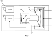
- Fig. 1 illustrates an exemplary system 100 for performing diagnostics on a transformer.
- the system 100 includes a voltage generator section 105, a switch section 110, a processor 120, and a storage device 125.
- the voltage generator section 105 includes a voltage source 106 and a current measuring device 107.
- the voltage source is configured to generate a voltage that is typically lower than the voltage applied to the target transformer when in normal in-service use.
- the test voltage may be about 12 kV.
- the resulting current into the target transformer may be a non-sinusoidal AC current.
- the current measuring device 107 is configured to measure the excitation current flowing from the voltage source 106 to the winding of a target transformer.
- the current measuring device 107 may include a current sensing portion, such as a small resistance. Current flowing through the resistance results in a voltage drop across the resistance.
- the current measuring device 107 may include analog-to-digital conversion circuitry that samples the voltage developed across the resistance and communicates a digital representation of the sampled voltage to the processor 120.
- the switch section 110 is configured to route the outputs of the voltage generator section 105 to different windings of a target transformer.
- the switch section 110 may correspond to a mechanical or solid-state switch.
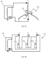
- Figs. 2A and 2B illustrate exemplary transformer configurations that may be coupled to the switch section 110.
- Fig. 2A illustrates a Y-type transformer 205 that includes an LTC/DETC 210.
- the switch section 110 may couple a first voltage generator output to a center node, H0, of the transformer 205.
- the switch section 110 may couple the other output to one of nodes H1, H2, and H3 to facilitate measuring the excitation current flowing within one of windings H1-H0, H2-H0, or H3-H0.
- FIG. 2B illustrates a different transformer 215 that includes an LTC/DETC 220 where access to a neutral node of the transformer may not be provided.
- the switch section 110 may couple the outputs of the voltage generator section 105 to one of nodes H1, H2, and H3, to facilitate measuring the excitation current flowing within one of windings/phases H1-H2, H1-H3, or H2-H3.
- the processor 120 is configured to compare the current components associated with the exciting current with previously determined component data associated with the target transformer or benchmark transformers.
- the processor 120 may be in communication with the voltage generator section 105 and the switch section 110 to control operation of the respective sections.
- the processor 120 may control activation of the voltage generator 106 of the voltage generator section 105 and may control an output voltage and frequency of the voltage generator section 105.
- the processor 120 may control the switch configuration of the switch section 110 to route voltage from the voltage regulator section 105 to select a specific winding/phase of a target transformer.
- the processor 120 may be configured to communicate information and/or instructions to an operator.
- the system 100 may include a display or a network interface that facilitates communication of instructions to an operator to have the operator select a particular LTC/DETC position when testing the operation of a target transformer.
- the processor 120 may be in control of a servo or other form of actuator that is coupled to the LTC/DETC of the target transformer to facilitate automatic changing of the LTC/DETC position during testing.
- Non-transitory types of memories such as RAM, ROM, flash, etc.
- RAM random access memory
- ROM read-only memory
- flash flash
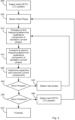
- selection of an initial LTC/DETC position may be performed.
- an instruction for setting the LTC/DETC position of the target transformer to an initial position such as LTC/DETC position 1
- LTC/DETC position 1 an instruction for setting the LTC/DETC position of the target transformer to an initial position, such as LTC/DETC position 1
- the switch section 110 may be controlled to route voltage outputs of the voltage generator section 105 to a first phase or winding of the target transformer.
- the processor 120 may control the switch section 110 to select phase H1-H3 of the transformer, as illustrated in Fig. 2B .
- the voltage generator 106 of the voltage generator section 105 may be energized at a first frequency, and the current phasor of the exciting current associated with the first frequency may be captured.
- the voltage generator 106 may generate a 12 kV sinusoidal AC voltage at a frequency about 5% below a normal operating frequency of the target transformer, such as 57 Hz when the normal operating frequency is 60 Hz. A lower frequency may result in the inductance of the transformer becoming non-linear. Generation of the voltage results in exciting current flow through the selected winding/phase of the target transformer.
- the current measuring device 107 of the voltage generator section 105 may measure the magnitude and phase of the current with respect to the phase of the voltage source to determine in-phase (I) and out-of-phase (Q) components of the current flowing into the target transformer.
- the current measuring device 107 may digitally sample a voltage developed across a sense resistor and based on the samples determine the in-phase (I) and out-of-phase (Q) components of the current.
- the current flowing into the target transformer may be a non-sinusoidal AC current.
- determination of the I and Q components of the current may require determining the first harmonic waveform of the measured current.
- a filter or harmonic analyzer may be utilized to determine the first harmonic.
- Fig. 4A illustrates various currents flowing through-out an exemplary circuit representation 400 of a single phase of a transformer.
- the transformer phase may be represented as the parallel combination of inductor L m , resistor R m , and capacitor C.
- the voltage source sources current I m into the parallel combination of components, where I m equals the sum of currents I L , I R , and I C , which flow respectively through inductor L m , resistor R m , and capacitor C.
- Fig. 4B illustrates a vector representation of the various current components.
- the in-phase current (I R ) corresponds to the current I R , that flows through the equivalent resistance of the transformer phase.
- the magnitude of the out-of-phase current (I Q ) corresponds to the difference between the magnitudes of currents I L and I C that flow respectively through the equivalent inductor and capacitor of the transformer phase.
- the voltage generator 106 of the voltage generator section 105 may be energized at a second frequency, and the in-phase (I) and out-of-phase (Q) components current phasor of the exciting current associated with the second frequency may be captured.
- the voltage generator 106 may be controlled to generate a 12 kV sinusoidal AC voltage at a frequency about 5% above a normal operating frequency of the target transformer, such as 63 Hz when the normal operating frequency is 60 Hz. A higher frequency may result in the inductance of the transformer becoming non-linear.
- the in-phase (I) and out-of-phase (Q) components of the current at this frequency may be captured.
- the currents I L and I C flowing through inductor L m and capacitor C, respectively may be determined based on the in-phase (I) and out-of-phase (Q) component current measurements performed in blocks 310 and 315.
- the currents associated with the inductive and capacitive components are determined according to the following methodology:
- I L 1 V / j ⁇ 1 L
- I C 1 jV ⁇ 1 C
- I L 2 V / j ⁇ 2 L
- I C 2 jV ⁇ 2 C
- I L V / j ⁇ L
- I C jV ⁇ C
- the calculated currents, I L , I C , and measured current I R may be stored to the storage device 125 and associated with the current LTC/DETC position and current phase as illustrated in Table 1.
- a first record in the database may include the data associated with a first combination of LTC/DETC position and windings/phases.
- a second record includes the data associated with a second combination of LTC/DETC position and windings/phase.
- Data associated with other bridging and non-bridging LTC/DETC positions may be specified in additional records of the database.
- the data may be represented differently to facilitate searching the database according to the different types of patterns described above.
- records in the database may be arranged to facilitate searching the database for specific LTC/DETC patterns and/or phase patterns.
- the database may be searched according to the pattern type. For example, a phase pattern may be determined for a given combination of LTC/DETC position.
- the database may be searched for a record associated with the same LTC/DETC position, and the values of the record compared with the determined phase pattern.
- the data associated with the target transformer may be compared with data associated with one or more benchmark transformers. Comparison may be made on a measurement-by-measurement basis or on a different basis. For example, current measurements and or the computed currents above associated with all three phases and for all LTC/DETC positions may be compared with corresponding current measurements and or the computed currents of the one or more benchmark transformers. In this case, the current measurements and/or computed currents for all combinations of phases and LTC/DETC positions would have to be performed on the target transformer. Once completed, the current measurements and/or computed currents would be compared to determine whether the target transformer matches the characteristics of the benchmark transformer. In some instances, different weights may be applied to the various components to signify the importance of one component over another. For example, I L currents may be given a greater weight than I C currents.
- iterations through the operations described in Fig. 3 may terminate after an anomaly is first noticed with the target transformer. For example, if an anomaly is detected when performing diagnostics on a first LTC/DETC position, the operations may simply terminate at that point instead of continuing through all other LTC/DETC positions. For example, the calculations of the current components for a given LTC/DETC may be performed and then compared with the current component data associated with a benchmark transformer when set to the same LTC/DETC position. In this case, if the difference between the measurements of the target transformer and the benchmark transformer exceeds a threshold, further analysis on the target transformer may be discontinued.
- the measurements may instead be compared to measurements associated with one or more different benchmark transformers to find a benchmark transformer that has similar current component characteristics for the selected LTC/DETC. This may, for example, be utilized to determine a failure mode of the target transformer. For example, the measurements associated with a given LTC/DETC position of the target transformer may match a benchmark transformer that has a shorted winding on the same phase. If the measurements match between the target transformer and the benchmark transformer, the target transformer may be determined to have a shorted winding.
- a three-phase transformer has three windings or sets of windings for each phase. In this case, the current components associated with exciting current flow through each phase or set of windings would be measured.
- the next LTC/DETC position may be selected and the operations may repeat from block 305. For example, if the target transformer has an LTC/DETC with 16 positions, each position may be selected and the measurements described above performed for all 16 positions.
- the LTC/DETC positions may include both non-bridging positions and bridging positions, which are positions where two adjacent taps of the target transformer are connected via a preventative autotransformer.
- diagnosis of the target transformer may be completed, as represented by block 370.
- comparison of the measurements associated with the target transformer to measurements associated with a benchmark transformer may occur after all combinations of LTC/DETC positions and windings/phases have been measured. In this case, comparison may occur at block 370. Alternatively, comparison may be performed after each LTC/DETC position and phase has been exercised.
- Fig. 5 illustrates a computer system 500 that may correspond to the processor 120 or form part of any of the modules referenced herein.
- the computer system 500 may include a set of instructions 545 that the processor 505 may execute to cause the computer system 500 to perform any of the operations described above.
- the computer system 500 may operate as a stand-alone device or may be connected, e.g., using a network, to other computer systems or peripheral devices.
- the computer system 500 may operate in the capacity of a server or as a client-user computer in a server-client user network environment, or as a peer computer system in a peer-to-peer (or distributed) network environment.
- the computer system 500 may also be implemented as or incorporated into various devices, such as a personal computer or a mobile device, capable of executing the instructions 545 (sequential or otherwise) that specify actions to be taken by that machine.
- each of the systems described may include any collection of sub-systems that individually or jointly execute a set, or multiple sets, of instructions to perform one or more computer functions.
- the computer system 500 may include one or more memory devices 510 on a bus for communicating information.
- code operable to cause the computer system to perform any of the operations described above may be stored in the memory 510.
- the memory 510 may be a random-access memory, read-only memory, programmable memory, hard disk drive or any other type of memory or storage device.
- the computer system 500 may include a display 530, such as a liquid crystal display (LCD), a cathode ray tube (CRT), or any other display suitable for conveying information.
- the display 530 may act as an interface for the user to see the functioning of the processor 505, or specifically as an interface with the software stored in the memory 510 or in the drive unit 515.
- the computer system 500 may include an input device 525, such as a keyboard or mouse, configured to allow a user to interact with any of the components of system 500.
- an input device 525 such as a keyboard or mouse
- the computer system 500 may also include a disk or optical drive unit 515.
- the disk drive unit 515 may include a computer-readable medium 540 in which the instructions 545 may be stored.
- the instructions 545 may reside completely, or at least partially, within the memory 510 and/or within the processor 505 during execution by the computer system 500.
- the memory 510 and the processor 505 also may include computer-readable media as discussed above.
- the computer system 500 may include a communication interface 535 to support communications via a network 550.
- the network 550 may include wired networks, wireless networks, or combinations thereof.
- the communication interface 535 network may enable communications via any number of communication standards, such as 802.11, 802.12, 802.20, WiMax, cellular telephone standards, or other communication standards.
- the method and system may be realized in hardware, software, or a combination of hardware and software.
- the method and system may be realized in a centralized fashion in at least one computer system or in a distributed fashion where different elements are spread across several interconnected computer systems. Any kind of computer system or other apparatus adapted for carrying out the methods described herein may be employed.
- the method and system may also be embedded in a computer program product, which includes all the features enabling the implementation of the operations described herein and which, when loaded in a computer system, is able to carry out these operations.
- Computer program in the present context means any expression, in any language, code or notation, of a set of instructions intended to cause a system having an information processing capability to perform a particular function, either directly or after either or both of the following: a) conversion to another language, code or notation; b) reproduction in a different material form.
- a method for performing diagnostics on a target transformer comprising:
- the target transformer is a three-phase transformer with a plurality of windings associated with the different phases, wherein the method further comprises performing steps (a)-(g) for each phase of the target transformer.
- the method may further be improved by the target transformer including a load-tap-changer (LTC) or a de-energized tap changer (DETC), wherein for each position of the LTC or DETC the method further comprises performing steps (a)-(g) for each of the LTC or DETC positions.
- LTC load-tap-changer
- DETC de-energized tap changer
- the improved method mentioned above may be further improved by further comprising
- the AC voltage generated by the voltage generator is at or below 12,000 Volts.
- the first and second frequencies correspond to about ⁇ 5% of a normal operating frequency of the target transformer.
- the benchmark transformers include properly functioning transformers and transformers that exhibit one or more defects.
- current component measurements associated with the one or more benchmark transformers are stored in a database.
- a system for performing diagnostics on a target transformer comprising:
- the target transformer is a three-phase transformer with a plurality of windings associated with the different phases, wherein the instruction code causes the processor to perform steps (a)-(g) for each phase of the target transformer.
- the system may further be improved by the target transformer including a load-tap-changer (LTC) or de-energized tap changer (DETC), wherein the instruction code causes the processor to perform steps (a)-(g) for each of the LTC or DETC positions.
- LTC load-tap-changer
- DETC de-energized tap changer
- the improved system mentioned above may be further improved by, further comprising instruction code that causes the processor to:
- the AC voltage generated by the voltage generator is at or below 12,000 Volts.
- the first and second frequencies correspond to about ⁇ 5% of a normal operating frequency of the target transformer.
- the benchmark transformers include properly functioning transformers and transformers that exhibit one or more defects.
- current component measurements associated with the one or more benchmark transformers are stored in a database.
- a non-transitory machine-readable storage medium having stored thereon a computer program comprising at least one code section for performing diagnostics on a target transformer, the at least one code section being executable by a machine for causing the machine to perform acts of:
- the AC voltage generated by the voltage generator is at or below 12,000 Volts.
- the first and second frequencies correspond to about ⁇ 5% of a normal operating frequency of the target transformer.
- the benchmark transformers include properly functioning transformers and transformers that exhibit one or more defects.
Landscapes
- Engineering & Computer Science (AREA)
- Power Engineering (AREA)
- Physics & Mathematics (AREA)
- General Physics & Mathematics (AREA)
- Control Of Eletrric Generators (AREA)
- Testing Of Short-Circuits, Discontinuities, Leakage, Or Incorrect Line Connections (AREA)
- Tests Of Circuit Breakers, Generators, And Electric Motors (AREA)
- Testing Relating To Insulation (AREA)
- Measurement Of Current Or Voltage (AREA)
- Testing Electric Properties And Detecting Electric Faults (AREA)
- Housings And Mounting Of Transformers (AREA)
Claims (20)
- Procédé mis en œuvre par un système de diagnostic pour effectuer des diagnostics sur un transformateur cible qui comprend une pluralité de phases, le procédé comprenant :la commande, par un processeur (120, 505) du système de diagnostic, d'un circuit de commutation (110) pour coupler un générateur de tension (105) à chacune de la pluralité de phases (205, 215) du transformateur cible ;pour chaque phase, le processeur (120, 505) effectue des actions comprenant :la commande du générateur de tension (105) pour délivrer une tension alternative à une première fréquence ;la mesure d'une amplitude et d'un angle de phase d'un premier courant d'excitation circulant dans le transformateur cible associé à la première fréquence, le premier courant d'excitation ayant des composantes inductive et capacitive, le procédé étant caractérisé par la commande du générateur de tension (105) pour délivrer une tension à une seconde fréquence ;la mesure d'une amplitude et d'un angle de phase d'un second courant d'excitation circulant dans le transformateur cible associé à la seconde fréquence, le second courant d'excitation ayant des composantes inductive et capacitive ;la détermination d'une grandeur d'une composante inductive et d'une grandeur d'une composante capacitive du transformateur cible à une fréquence de fonctionnement normale du transformateur cible en fonction des courants d'excitation aux première et seconde fréquences pour déterminer ainsi un modèle de grandeurs des composantes inductive et capacitive du courant d'excitation pour le transformateur cible ;la comparaison, par le processeur, du modèle déterminé pour le transformateur cible à des modèles associés à un ou plusieurs transformateurs de référence ayant des caractéristiques électriques connues ; etlorsque le modèle associé au transformateur cible correspond à un modèle de l'un des transformateurs de référence, la détermination des caractéristiques électriques du transformateur cible pour correspondre aux caractéristiques électriques du transformateur de référence,la comparaison du modèle pour le transformateur cible aux modèles des un ou plusieurs transformateurs de référence ayant des caractéristiques électriques connues facilitant la détermination si le transformateur cible est défectueux.
- Procédé selon la revendication 1, dans lequel le transformateur cible est un transformateur triphasé.
- Procédé selon la revendication 1, dans lequel le transformateur cible comprend un changeur de prise de charge [LTC] ou un changeur de prise hors tension [DETC] (210, 220), dans lequel le modèle d'amplitudes des composantes inductive et capacitive du courant d'excitation à la fréquence de fonctionnement normale du transformateur cible est déterminé pour chaque position du LTC ou du DETC.
- Procédé selon la revendication 1, dans lequel la tension alternative est égale ou inférieure à 12000 volts.
- Procédé selon la revendication 1, dans lequel les première et seconde fréquences correspondent à environ ±5 % de la fréquence de fonctionnement normale du transformateur cible.
- Procédé selon la revendication 1, dans lequel les un ou plusieurs transformateurs de référence comprennent des transformateurs fonctionnant correctement et des transformateurs qui présentent une ou plusieurs défaillances.
- Procédé selon la revendication 1, dans lequel les composantes inductive et capacitive du courant d'excitation à la fréquence de fonctionnement normale du transformateur cible associé aux un ou plusieurs transformateurs de référence sont stockées dans une base de données (125).
- Procédé selon la revendication 1, dans lequel la fréquence de fonctionnement normale correspond à une fréquence de fonctionnement normale d'un transformateur haute tension qui fournit de l'énergie à des utilisateurs résidentiels et commerciaux.
- Système permettant d'effectuer des diagnostics sur un transformateur cible qui comprend une pluralité de phases, le système comprenant :un générateur de tension (105) qui génère une tension alternative ;une section de commutation (110) configurée pour appliquer sélectivement la tension à chacune de la pluralité de phases du transformateur cible ;un capteur de courant (107) configuré pour détecter un courant circulant à travers une phase sélectionnée du transformateur cible ;un processeur (120, 505) en communication avec le générateur de tension (105), la section de commutation (110) et le capteur de courant (107) ; etun support lisible par ordinateur non transitoire (125) en communication avec le processeur (120, 505) qui stocke un code d'instruction qui, lorsqu'il est exécuté par le processeur, amène le processeur à effectuer des actions comprenant :la commande de la section de commutation (110) pour appliquer la tension alternative reçue à chaque phase du transformateur cible ;pour chaque phase :la commande du générateur de tension (105) pour délivrer une tension alternative à une première fréquence ;la mesure, via le capteur de courant (107), d'une amplitude et d'un angle de phase d'un premier courant d'excitation circulant dans le transformateur cible associé à la première fréquence, le premier courant d'excitation ayant des composantes inductive et capacitive ; caractérisé parla commande du générateur de tension (105) pour délivrer une tension à une seconde fréquence ;la mesure, via le capteur de courant (107), d'une amplitude et d'un angle de phase d'un second courant d'excitation circulant dans le transformateur cible associé à la seconde fréquence, le second courant d'excitation ayant des composantes inductive et capacitive ;la détermination d'une grandeur d'une composante inductive et d'une grandeur d'une composante capacitive du transformateur cible à une fréquence de fonctionnement normale du transformateur cible en fonction des courants d'excitation aux première et seconde fréquences pour déterminer ainsi un modèle de grandeurs des composantes inductive et capacitive du courant d'excitation pour le transformateur cible ;la comparaison du modèle déterminé pour le transformateur cible à des modèles associés à un ou plusieurs transformateurs de référence ayant des caractéristiques électriques connues ; etlorsque le modèle associé au transformateur cible correspond à un modèle de l'un des transformateurs de référence, la détermination des caractéristiques électriques du transformateur cible pour correspondre aux caractéristiques électriques du transformateur de référence,la comparaison du modèle du transformateur cible aux modèles des un ou plusieurs transformateurs de référence ayant des caractéristiques électriques connues facilitant la détermination si le transformateur cible est défectueux.
- Système selon la revendication 9, dans lequel le transformateur cible est un transformateur triphasé.
- Système selon la revendication 9, dans lequel le transformateur cible comprend un changeur de prise de charge [LTC] ou un changeur de prise hors tension [DETC] (210, 220), dans lequel le code d'instruction amène le processeur à déterminer le modèle d'amplitudes des composantes inductive et capacitive du courant d'excitation à la fréquence de fonctionnement normale du transformateur cible pour chaque position des positions LTC ou DETC.
- Système selon la revendication 9, dans lequel la tension est égale ou inférieure à 12000 volts.
- Système selon la revendication 9, dans lequel les première et seconde fréquences correspondent à environ ±5 % de la fréquence de fonctionnement normale du transformateur cible.
- Système selon la revendication 9, dans lequel les un ou plusieurs transformateurs de référence comprennent des transformateurs fonctionnant correctement et des transformateurs qui présentent une ou plusieurs défaillances.
- Système selon la revendication 9, dans lequel les composantes inductive et capacitive du courant d'excitation à la fréquence de fonctionnement normale du transformateur cible associé aux un ou plusieurs transformateurs de référence sont stockées dans une base de données.
- Système selon la revendication 9, dans lequel la fréquence de fonctionnement normale correspond à une fréquence de fonctionnement normale d'un transformateur haute tension qui fournit de l'énergie à des utilisateurs résidentiels et commerciaux.
- Support de stockage non transitoire lisible par machine sur lequel est stocké un programme informatique comprenant au moins une section de code pour effectuer des diagnostics sur un transformateur cible qui comprend une pluralité de phases, l'au moins une section de code étant exécutable par une machine pour amener la machine à effectuer des actions consistant à :commander un circuit de commutation (110) pour appliquer une sortie de tension à chacune de la pluralité de phases du transformateur cible ;pour chaque phase :commander le générateur de tension (105) pour délivrer une tension à une première fréquence ;mesurer une amplitude et un angle de phase d'un premier courant d'excitation circulant dans le transformateur cible associé à la première fréquence, le premier courant d'excitation ayant des composantes inductive et capacitive ; caractérisé parla commande du générateur de tension (105) pour délivrer une tension à une seconde fréquence ;la mesure d'une amplitude et d'un angle de phase d'un second courant d'excitation circulant dans le transformateur cible associé à la seconde fréquence, le second courant d'excitation ayant des composantes inductive et capacitive ;la détermination d'une amplitude d'une composante inductive et d'une amplitude d'une composante capacitive du transformateur cible à une fréquence de fonctionnement normale du transformateur cible en fonction des courants d'excitation aux première et seconde fréquences pour déterminer ainsi un modèle d'amplitudes des composantes inductive et capacitive du courant d'excitation pour le transformateur cible ;la comparaison du modèle déterminé pour le transformateur cible à des modèles associés à un ou plusieurs transformateurs de référence ayant des caractéristiques électriques connues ; etlorsque le modèle associé au transformateur cible correspond à un modèle de l'un des transformateurs de référence, la détermination des caractéristiques électriques du transformateur cible pour qu'elles correspondent aux caractéristiques électriques du transformateur de référence,la comparaison du modèle du transformateur cible aux modèles des un ou plusieurs transformateurs de référence ayant des caractéristiques électriques connues facilitant la détermination si le transformateur cible est défectueux.
- Support de stockage non transitoire lisible par machine selon la revendication 17, dans lequel les première et seconde fréquences correspondent à environ ± 5 % d'une fréquence de fonctionnement normale du transformateur cible.
- Support de stockage non transitoire lisible par machine selon la revendication 17, dans lequel les un ou plusieurs transformateurs de référence comprennent des transformateurs fonctionnant correctement et des transformateurs qui présentent une ou plusieurs défaillances.
- Support de stockage non transitoire lisible par machine selon la revendication 17, dans lequel la fréquence de fonctionnement normale correspond à une fréquence de fonctionnement normale d'un transformateur haute tension qui fournit de l'énergie à des utilisateurs résidentiels et commerciaux.
Applications Claiming Priority (3)
| Application Number | Priority Date | Filing Date | Title |
|---|---|---|---|
| US15/436,403 US10203364B2 (en) | 2017-02-17 | 2017-02-17 | System and method for performing transformer diagnostics |
| PCT/US2018/018018 WO2018152114A1 (fr) | 2017-02-17 | 2018-02-13 | Système et procédé de réalisation de diagnostics de transformateur |
| EP18748842.4A EP3405802B1 (fr) | 2017-02-17 | 2018-02-13 | Système et procédé de réalisation de diagnostics de transformateur |
Related Parent Applications (1)
| Application Number | Title | Priority Date | Filing Date |
|---|---|---|---|
| EP18748842.4A Division EP3405802B1 (fr) | 2017-02-17 | 2018-02-13 | Système et procédé de réalisation de diagnostics de transformateur |
Publications (3)
| Publication Number | Publication Date |
|---|---|
| EP4145162A1 EP4145162A1 (fr) | 2023-03-08 |
| EP4145162C0 EP4145162C0 (fr) | 2025-06-18 |
| EP4145162B1 true EP4145162B1 (fr) | 2025-06-18 |
Family
ID=63167099
Family Applications (2)
| Application Number | Title | Priority Date | Filing Date |
|---|---|---|---|
| EP22200885.6A Active EP4145162B1 (fr) | 2017-02-17 | 2018-02-13 | Système et procédé pour effectuer des diagnostics de transformateur |
| EP18748842.4A Active EP3405802B1 (fr) | 2017-02-17 | 2018-02-13 | Système et procédé de réalisation de diagnostics de transformateur |
Family Applications After (1)
| Application Number | Title | Priority Date | Filing Date |
|---|---|---|---|
| EP18748842.4A Active EP3405802B1 (fr) | 2017-02-17 | 2018-02-13 | Système et procédé de réalisation de diagnostics de transformateur |
Country Status (9)
| Country | Link |
|---|---|
| US (3) | US10203364B2 (fr) |
| EP (2) | EP4145162B1 (fr) |
| JP (1) | JP7303747B2 (fr) |
| CN (1) | CN110168386B (fr) |
| AU (1) | AU2018221452B2 (fr) |
| BR (1) | BR112019012138B1 (fr) |
| MX (2) | MX393812B (fr) |
| WO (1) | WO2018152114A1 (fr) |
| ZA (2) | ZA201903761B (fr) |
Families Citing this family (7)
| Publication number | Priority date | Publication date | Assignee | Title |
|---|---|---|---|---|
| US11105838B2 (en) * | 2018-01-19 | 2021-08-31 | Avo Multi-Amp Corporation | System and method for measuring turns ratio of a transformer |
| CN111679237B (zh) * | 2020-06-05 | 2022-11-29 | 郑州科尔物联科技有限公司 | 一种电流互感器检测方法 |
| CN112285616B (zh) * | 2020-09-24 | 2022-05-06 | 国网河北省电力有限公司 | 一种快速判断电气设备内部故障的方法及装置 |
| CN113484801A (zh) * | 2021-07-15 | 2021-10-08 | 杭州电力设备制造有限公司 | 一种变压器绕组状态的检测方法、装置、设备及介质 |
| SE545723C2 (en) * | 2021-12-30 | 2023-12-19 | Megger Sweden Ab | Method and device for measuring high voltage devices using a correction factor |
| US12094651B2 (en) | 2022-01-10 | 2024-09-17 | Doble Engineering Company | Optimizing transformer exciting current and loss test results by dynamically managing core magnetic state |
| CN119808500B (zh) * | 2025-02-17 | 2026-03-06 | 西安西电变压器有限责任公司 | 基于变压器负载损耗的时谐场激励等效方法及相关装置 |
Family Cites Families (32)
| Publication number | Priority date | Publication date | Assignee | Title |
|---|---|---|---|---|
| US3314006A (en) * | 1965-04-19 | 1967-04-11 | Automation Forster Inc | Variable frequency eddy current test device with variable means for maintaining the apparent impedance of the probe constant at all frequencies |
| JPH0645270Y2 (ja) * | 1988-06-13 | 1994-11-16 | 日新電機株式会社 | 絶縁抵抗測定装置 |
| US5216356A (en) | 1990-11-13 | 1993-06-01 | Southwest Electric Company | Shielded three phase transformer with tertiary winding |
| JPH11344524A (ja) * | 1998-06-02 | 1999-12-14 | Meidensha Corp | 多層巻線のレアー判定方法 |
| US6853939B2 (en) * | 2002-01-18 | 2005-02-08 | Georgia Tech Research Corporation | Systems and methods for multiple winding impulse frequency response analysis test |
| US8150643B1 (en) * | 2004-12-21 | 2012-04-03 | Battelle Energy Alliance, Llc | Method of detecting system function by measuring frequency response |
| US7469190B2 (en) | 2005-07-01 | 2008-12-23 | Square D Company | Automated system approach to analyzing harmonic distortion in an electric power system |
| NL1033148C2 (nl) * | 2006-12-29 | 2008-07-01 | Univ Delft Tech | Elektrische meetinrichting, werkwijze en computer programma product. |
| JP4983441B2 (ja) * | 2007-07-05 | 2012-07-25 | 東京電力株式会社 | 短絡判定装置、短絡判定方法 |
| ES2745414T3 (es) * | 2007-08-16 | 2020-03-02 | Radian Res Inc | Equipo y procedimiento de prueba de transformador de instrumentos |
| KR100998577B1 (ko) | 2007-08-29 | 2010-12-07 | 주식회사 와튼 | 전력변환장치의 노화상태 진단장치 및 이의 진단방법 |
| US8428895B2 (en) * | 2008-10-28 | 2013-04-23 | Avo Multi-Amp Corporation | System and method for power system parameter measurement |
| JP5407480B2 (ja) * | 2009-03-27 | 2014-02-05 | 東京電力株式会社 | 変圧器の内部診断方法 |
| JP5448154B2 (ja) * | 2009-08-12 | 2014-03-19 | 株式会社高岳製作所 | 変圧器故障判定器 |
| US8476874B2 (en) | 2009-10-13 | 2013-07-02 | Schweitzer Engineering Laboratories, Inc | Systems and methods for synchronized control of electrical power system voltage profiles |
| JP5560432B2 (ja) * | 2010-03-31 | 2014-07-30 | 株式会社東光高岳 | 変圧器故障判定器 |
| JP2011253885A (ja) * | 2010-06-01 | 2011-12-15 | Central Res Inst Of Electric Power Ind | 変圧器の健全性診断方法、健全性診断装置及び健全性診断プログラム |
| JP5456582B2 (ja) * | 2010-06-01 | 2014-04-02 | 一般財団法人電力中央研究所 | 変圧器の健全性診断方法、健全性診断装置及び健全性診断プログラム |
| ES2439279T3 (es) | 2010-12-17 | 2014-01-22 | Abb Research Ltd. | Método y aparato para diagnóstico de transformador |
| EP2482415A1 (fr) | 2011-01-31 | 2012-08-01 | Alstom Technology Ltd | Procédé de contrôle de changeur de prise en charge, système de contrôle de l'excitation réalisant ledit procédé de contrôle et chaîne d'excitation de puissance |
| EP2686690B1 (fr) * | 2011-03-18 | 2017-06-14 | ABB Research Ltd. | Procédé et dispositif pour linéariser un transformateur |
| CN202533520U (zh) * | 2012-03-08 | 2012-11-14 | 上海东普电器制造有限公司 | 电感电流承载测试系统 |
| US9052350B2 (en) * | 2012-07-31 | 2015-06-09 | General Electric Company | On-line monitoring system for use with electrical assets and method of operating the same |
| US9128134B2 (en) * | 2012-10-25 | 2015-09-08 | Avo Multi-Amp Corporation | Concurrent transformer test system and method |
| US9385524B2 (en) * | 2013-10-04 | 2016-07-05 | General Electric Company | Arc flash mitigation system for use with generator excitation system |
| US10075117B2 (en) | 2014-02-03 | 2018-09-11 | Johnson Controls Technology Company | Multi-pulse constant voltage transformer for a variable speed drive in chiller applications |
| AU2015231695B2 (en) * | 2014-03-21 | 2019-07-25 | Doble Engineering Company | System and method for performing transformer diagnostics |
| US20160140263A1 (en) * | 2014-11-18 | 2016-05-19 | General Electric Company | System and method for determining the current and future state of health of a power transformer |
| CN107407705A (zh) * | 2015-01-13 | 2017-11-28 | 欧米克朗电子有限公司 | 变压器测试装置和变压器测试方法 |
| CN105093140B (zh) * | 2015-08-19 | 2018-03-20 | 国网四川省电力公司阿坝供电公司 | 一种变压器剩磁检测及消磁的方法及其装置 |
| CN105352427B (zh) * | 2015-10-20 | 2017-11-14 | 江苏省电力公司淮安供电公司 | 一种变压器绕组变形量在线检测方法 |
| CN106199285B (zh) * | 2016-08-20 | 2023-05-16 | 福州大学 | 任意交流载波下的电容特性测量设备及其测量方法 |
-
2017
- 2017-02-17 US US15/436,403 patent/US10203364B2/en active Active
-
2018
- 2018-02-13 JP JP2019542211A patent/JP7303747B2/ja active Active
- 2018-02-13 EP EP22200885.6A patent/EP4145162B1/fr active Active
- 2018-02-13 CN CN201880005433.2A patent/CN110168386B/zh active Active
- 2018-02-13 MX MX2020009969A patent/MX393812B/es unknown
- 2018-02-13 MX MX2019007627A patent/MX375337B/es active IP Right Grant
- 2018-02-13 BR BR112019012138-2A patent/BR112019012138B1/pt active IP Right Grant
- 2018-02-13 AU AU2018221452A patent/AU2018221452B2/en active Active
- 2018-02-13 WO PCT/US2018/018018 patent/WO2018152114A1/fr not_active Ceased
- 2018-02-13 EP EP18748842.4A patent/EP3405802B1/fr active Active
-
2019
- 2019-01-29 US US16/261,309 patent/US10545183B2/en active Active
- 2019-06-11 ZA ZA2019/03761A patent/ZA201903761B/en unknown
-
2020
- 2020-01-24 US US16/752,125 patent/US11156671B2/en active Active
- 2020-09-22 ZA ZA2020/05858A patent/ZA202005858B/en unknown
Also Published As
| Publication number | Publication date |
|---|---|
| MX2019007627A (es) | 2019-09-06 |
| MX393812B (es) | 2025-03-24 |
| AU2018221452A1 (en) | 2019-06-20 |
| EP3405802B1 (fr) | 2022-10-12 |
| ZA201903761B (en) | 2022-07-27 |
| ZA202005858B (en) | 2022-01-26 |
| WO2018152114A1 (fr) | 2018-08-23 |
| US20180238953A1 (en) | 2018-08-23 |
| US10203364B2 (en) | 2019-02-12 |
| JP2020510815A (ja) | 2020-04-09 |
| AU2018221452B2 (en) | 2023-12-07 |
| AU2018221452A2 (en) | 2020-12-10 |
| EP4145162A1 (fr) | 2023-03-08 |
| US11156671B2 (en) | 2021-10-26 |
| BR112019012138B1 (pt) | 2024-03-12 |
| CN110168386A (zh) | 2019-08-23 |
| EP4145162C0 (fr) | 2025-06-18 |
| MX375337B (es) | 2025-03-06 |
| EP3405802A4 (fr) | 2019-10-16 |
| US20190154747A1 (en) | 2019-05-23 |
| BR112019012138A2 (pt) | 2020-06-02 |
| US20200158789A1 (en) | 2020-05-21 |
| CN110168386B (zh) | 2022-03-15 |
| EP3405802A1 (fr) | 2018-11-28 |
| MX2020009969A (es) | 2022-07-08 |
| JP7303747B2 (ja) | 2023-07-05 |
| US10545183B2 (en) | 2020-01-28 |
Similar Documents
| Publication | Publication Date | Title |
|---|---|---|
| EP4145162B1 (fr) | Système et procédé pour effectuer des diagnostics de transformateur | |
| EP3120162B1 (fr) | Système et procédé pour effectuer un diagnostic de transformateur | |
| US20150168478A1 (en) | Method and apparatus for measuring load tap changer characteristics | |
| CN107576862B (zh) | 监视无功功率补偿系统的装置及其方法 | |
| US11105838B2 (en) | System and method for measuring turns ratio of a transformer | |
| JP2006500551A (ja) | 変成器テストのための自動化されたテストシーケンス編集装置およびエンジン | |
| JP2020510815A5 (fr) | ||
| CN112162156A (zh) | 电阻测量器、方法、装置、设备及存储介质 | |
| EP2378296B1 (fr) | Procédé et agencement pour déterminer des valeurs d'impédance | |
| CN112986893A (zh) | 全自动电流互感器校验方法、装置、设备及存储介质 | |
| EP4428549A1 (fr) | Commande de gain de système de mesure de courant par spectroscopie d'impédance électrochimique | |
| US20250044374A1 (en) | Method and device for measuring high voltage devices using a correction factor | |
| EP4428548A1 (fr) | Étalonnage de système de mesure de courant par spectroscopie d'impédance électrochimique | |
| EP4428546A1 (fr) | Système de mesure de courant par spectroscopie d'impédance électrochimique comprenant un courant continu | |
| KR20240014191A (ko) | 이동형 다회로 변압기를 이용한 전력설비 테스트장치 및 그 방법 | |
| JP2023156092A (ja) | 変圧器の試験方法、試験方法に用いる試験装置 | |
| CN202330693U (zh) | 互感器负载装置和互感器检测装置 |
Legal Events
| Date | Code | Title | Description |
|---|---|---|---|
| PUAI | Public reference made under article 153(3) epc to a published international application that has entered the european phase |
Free format text: ORIGINAL CODE: 0009012 |
|
| STAA | Information on the status of an ep patent application or granted ep patent |
Free format text: STATUS: THE APPLICATION HAS BEEN PUBLISHED |
|
| AC | Divisional application: reference to earlier application |
Ref document number: 3405802 Country of ref document: EP Kind code of ref document: P |
|
| AK | Designated contracting states |
Kind code of ref document: A1 Designated state(s): AL AT BE BG CH CY CZ DE DK EE ES FI FR GB GR HR HU IE IS IT LI LT LU LV MC MK MT NL NO PL PT RO RS SE SI SK SM TR |
|
| STAA | Information on the status of an ep patent application or granted ep patent |
Free format text: STATUS: REQUEST FOR EXAMINATION WAS MADE |
|
| 17P | Request for examination filed |
Effective date: 20230811 |
|
| RBV | Designated contracting states (corrected) |
Designated state(s): AL AT BE BG CH CY CZ DE DK EE ES FI FR GB GR HR HU IE IS IT LI LT LU LV MC MK MT NL NO PL PT RO RS SE SI SK SM TR |
|
| GRAP | Despatch of communication of intention to grant a patent |
Free format text: ORIGINAL CODE: EPIDOSNIGR1 |
|
| STAA | Information on the status of an ep patent application or granted ep patent |
Free format text: STATUS: GRANT OF PATENT IS INTENDED |
|
| RIC1 | Information provided on ipc code assigned before grant |
Ipc: G01R 31/62 20200101AFI20250114BHEP |
|
| INTG | Intention to grant announced |
Effective date: 20250127 |
|
| GRAS | Grant fee paid |
Free format text: ORIGINAL CODE: EPIDOSNIGR3 |
|
| GRAA | (expected) grant |
Free format text: ORIGINAL CODE: 0009210 |
|
| STAA | Information on the status of an ep patent application or granted ep patent |
Free format text: STATUS: THE PATENT HAS BEEN GRANTED |
|
| AC | Divisional application: reference to earlier application |
Ref document number: 3405802 Country of ref document: EP Kind code of ref document: P |
|
| AK | Designated contracting states |
Kind code of ref document: B1 Designated state(s): AL AT BE BG CH CY CZ DE DK EE ES FI FR GB GR HR HU IE IS IT LI LT LU LV MC MK MT NL NO PL PT RO RS SE SI SK SM TR |
|
| REG | Reference to a national code |
Ref country code: GB Ref legal event code: FG4D |
|
| REG | Reference to a national code |
Ref country code: CH Ref legal event code: EP |
|
| REG | Reference to a national code |
Ref country code: DE Ref legal event code: R096 Ref document number: 602018082823 Country of ref document: DE |
|
| REG | Reference to a national code |
Ref country code: CH Ref legal event code: EP |
|
| REG | Reference to a national code |
Ref country code: IE Ref legal event code: FG4D |
|
| U01 | Request for unitary effect filed |
Effective date: 20250627 |
|
| U07 | Unitary effect registered |
Designated state(s): AT BE BG DE DK EE FI FR IT LT LU LV MT NL PT RO SE SI Effective date: 20250704 |
|
| PG25 | Lapsed in a contracting state [announced via postgrant information from national office to epo] |
Ref country code: GR Free format text: LAPSE BECAUSE OF FAILURE TO SUBMIT A TRANSLATION OF THE DESCRIPTION OR TO PAY THE FEE WITHIN THE PRESCRIBED TIME-LIMIT Effective date: 20250919 |
|
| PG25 | Lapsed in a contracting state [announced via postgrant information from national office to epo] |
Ref country code: HR Free format text: LAPSE BECAUSE OF FAILURE TO SUBMIT A TRANSLATION OF THE DESCRIPTION OR TO PAY THE FEE WITHIN THE PRESCRIBED TIME-LIMIT Effective date: 20250618 |
|
| PG25 | Lapsed in a contracting state [announced via postgrant information from national office to epo] |
Ref country code: RS Free format text: LAPSE BECAUSE OF FAILURE TO SUBMIT A TRANSLATION OF THE DESCRIPTION OR TO PAY THE FEE WITHIN THE PRESCRIBED TIME-LIMIT Effective date: 20250918 |
|
| PG25 | Lapsed in a contracting state [announced via postgrant information from national office to epo] |
Ref country code: IS Free format text: LAPSE BECAUSE OF FAILURE TO SUBMIT A TRANSLATION OF THE DESCRIPTION OR TO PAY THE FEE WITHIN THE PRESCRIBED TIME-LIMIT Effective date: 20251018 |
|
| PG25 | Lapsed in a contracting state [announced via postgrant information from national office to epo] |
Ref country code: SM Free format text: LAPSE BECAUSE OF FAILURE TO SUBMIT A TRANSLATION OF THE DESCRIPTION OR TO PAY THE FEE WITHIN THE PRESCRIBED TIME-LIMIT Effective date: 20250618 |
|
| PG25 | Lapsed in a contracting state [announced via postgrant information from national office to epo] |
Ref country code: CZ Free format text: LAPSE BECAUSE OF FAILURE TO SUBMIT A TRANSLATION OF THE DESCRIPTION OR TO PAY THE FEE WITHIN THE PRESCRIBED TIME-LIMIT Effective date: 20250618 |
|
| PG25 | Lapsed in a contracting state [announced via postgrant information from national office to epo] |
Ref country code: PL Free format text: LAPSE BECAUSE OF FAILURE TO SUBMIT A TRANSLATION OF THE DESCRIPTION OR TO PAY THE FEE WITHIN THE PRESCRIBED TIME-LIMIT Effective date: 20250618 |
|
| PG25 | Lapsed in a contracting state [announced via postgrant information from national office to epo] |
Ref country code: SK Free format text: LAPSE BECAUSE OF FAILURE TO SUBMIT A TRANSLATION OF THE DESCRIPTION OR TO PAY THE FEE WITHIN THE PRESCRIBED TIME-LIMIT Effective date: 20250618 |
|
| PG25 | Lapsed in a contracting state [announced via postgrant information from national office to epo] |
Ref country code: ES Free format text: LAPSE BECAUSE OF FAILURE TO SUBMIT A TRANSLATION OF THE DESCRIPTION OR TO PAY THE FEE WITHIN THE PRESCRIBED TIME-LIMIT Effective date: 20250618 |
|
| REG | Reference to a national code |
Ref country code: CH Ref legal event code: U11 Free format text: ST27 STATUS EVENT CODE: U-0-0-U10-U11 (AS PROVIDED BY THE NATIONAL OFFICE) Effective date: 20260301 |
|
| U20 | Renewal fee for the european patent with unitary effect paid |
Year of fee payment: 9 Effective date: 20260227 |
|
| PGFP | Annual fee paid to national office [announced via postgrant information from national office to epo] |
Ref country code: GB Payment date: 20260227 Year of fee payment: 9 |
|
| PGFP | Annual fee paid to national office [announced via postgrant information from national office to epo] |
Ref country code: NO Payment date: 20260227 Year of fee payment: 9 |
|
| PGFP | Annual fee paid to national office [announced via postgrant information from national office to epo] |
Ref country code: TR Payment date: 20260127 Year of fee payment: 9 |
|
| PLBE | No opposition filed within time limit |
Free format text: ORIGINAL CODE: 0009261 |
|
| STAA | Information on the status of an ep patent application or granted ep patent |
Free format text: STATUS: NO OPPOSITION FILED WITHIN TIME LIMIT |