EP4146366B1 - Appareil de filtration - Google Patents
Appareil de filtration Download PDFInfo
- Publication number
- EP4146366B1 EP4146366B1 EP22716426.6A EP22716426A EP4146366B1 EP 4146366 B1 EP4146366 B1 EP 4146366B1 EP 22716426 A EP22716426 A EP 22716426A EP 4146366 B1 EP4146366 B1 EP 4146366B1
- Authority
- EP
- European Patent Office
- Prior art keywords
- filter
- filter element
- housing
- filter apparatus
- valve closing
- Prior art date
- Legal status (The legal status is an assumption and is not a legal conclusion. Google has not performed a legal analysis and makes no representation as to the accuracy of the status listed.)
- Active
Links
Images


Classifications
-
- B—PERFORMING OPERATIONS; TRANSPORTING
- B01—PHYSICAL OR CHEMICAL PROCESSES OR APPARATUS IN GENERAL
- B01D—SEPARATION
- B01D29/00—Filters with filtering elements stationary during filtration, e.g. pressure or suction filters, not covered by groups B01D24/00 - B01D27/00; Filtering elements therefor
- B01D29/11—Filters with filtering elements stationary during filtration, e.g. pressure or suction filters, not covered by groups B01D24/00 - B01D27/00; Filtering elements therefor with bag, cage, hose, tube, sleeve or like filtering elements
- B01D29/13—Supported filter elements
- B01D29/15—Supported filter elements arranged for inward flow filtration
-
- B—PERFORMING OPERATIONS; TRANSPORTING
- B01—PHYSICAL OR CHEMICAL PROCESSES OR APPARATUS IN GENERAL
- B01D—SEPARATION
- B01D35/00—Filtering devices having features not specifically covered by groups B01D24/00 - B01D33/00, or for applications not specifically covered by groups B01D24/00 - B01D33/00; Auxiliary devices for filtration; Filter housing constructions
- B01D35/14—Safety devices specially adapted for filtration; Devices for indicating clogging
- B01D35/147—Bypass or safety valves
-
- B—PERFORMING OPERATIONS; TRANSPORTING
- B01—PHYSICAL OR CHEMICAL PROCESSES OR APPARATUS IN GENERAL
- B01D—SEPARATION
- B01D35/00—Filtering devices having features not specifically covered by groups B01D24/00 - B01D33/00, or for applications not specifically covered by groups B01D24/00 - B01D33/00; Auxiliary devices for filtration; Filter housing constructions
- B01D35/14—Safety devices specially adapted for filtration; Devices for indicating clogging
- B01D35/157—Flow control valves: Damping or calibrated passages
- B01D35/1573—Flow control valves
-
- B—PERFORMING OPERATIONS; TRANSPORTING
- B01—PHYSICAL OR CHEMICAL PROCESSES OR APPARATUS IN GENERAL
- B01D—SEPARATION
- B01D2201/00—Details relating to filtering apparatus
- B01D2201/29—Filter cartridge constructions
- B01D2201/291—End caps
- B01D2201/296—Other than having a circular shape
-
- B—PERFORMING OPERATIONS; TRANSPORTING
- B01—PHYSICAL OR CHEMICAL PROCESSES OR APPARATUS IN GENERAL
- B01D—SEPARATION
- B01D2201/00—Details relating to filtering apparatus
- B01D2201/40—Special measures for connecting different parts of the filter
- B01D2201/4092—Threaded sections, e.g. screw
Definitions
- the invention relates to a filter device with the features in the preamble of claim 1.
- Such a filter device is known from the subsequently published DE 10 2020 004 489 known.
- the filter device has a filter housing which has a connection point for the supply of an unfiltered stream and another connection point for the discharge of a filtrate stream.
- a hollow cylindrical filter element with a filter material is arranged in the filter device in order to filter the unfiltered stream.
- a separating device is also provided in order to separate the connection points from one another. This separating device is arranged in the filter housing in the form of an inclined partition wall and can be rotated to block off the supply and discharge.
- Such a filter device offers many advantages when changing the filter element, in particular when the hydraulic lines connected to the connection points are depressurized, because then the filter element can be removed from the filter device after unscrewing a cover, with relatively little fluid flowing from the hydraulic lines into the filter housing.
- the IT MI20 111 315 A1 describes a filter device with a filter housing which has at least two connection points, such as an inlet for unfiltered material and an outlet for filtrate, and accommodates a replaceable filter element, wherein at least one valve device is provided which, in an open position, enables a fluid flow between one of the connection points and the filter element and, in a closed position, prevents this fluid flow, and wherein the valve device is movable between the open position and the closed position by means of a control device, wherein one valve device is an inflow valve.
- the invention is based on the object of demonstrating an improved filter device which enables a service-friendly filter element change, in particular even when the hydraulic lines connected to the filter device are still under pressure.
- At least one valve device is provided which, in an open position, enables a fluid flow between one of the connection points and the filter element and, in a closed position, prevents this fluid flow; and the valve device can be moved between the open position and the closed position by means of a control device.
- the valve device can be moved between the open position and the closed position by means of a control device.
- the flow of hydraulic fluid into the housing during the filter element change can be safely prevented, even when the hydraulic lines are under pressure.
- This makes it possible to open the filter housing and replace the used filter element with a new element. made much easier. For example, there is no or fewer precautions to be taken against liquid dripping from the filter housing.
- the amount of liquid in the filter housing that could escape when the filter housing is opened is limited or at least greatly reduced.
- the inflow valve is arranged in the fluid flow between the inlet and an outside of the filter element and has an inflow valve closing member which is formed by a cylinder wall section provided with an opening which is arranged to be movable in a slot in the filter housing; and that the opening is in overlap with the inlet in the open position.
- the inflow valve closing member which is arranged to be movable in the filter housing provides an inflow valve which can also withstand very high pressures.
- An opening in the cylinder wall section can be in the form of a slot.
- a slot is very easy to create in the cylinder wall section and ensures that the opening has a maximum cross-section.
- the cylinder wall section is advantageously attached to a plate part that is arranged between the filter housing and the filter element; and the cylinder wall section preferably has at least one pin that is inserted into a hole in the plate part.
- the plate part takes on the function of a transmission element in order to transmit a movement of the control device to the inflow valve. The fact that only one pin is required, which is simply inserted into the plate part, also provides a particularly easy-to-assemble solution that is nevertheless sufficiently robust for daily use.
- the plate part can have several, preferably kidney-shaped, openings for the fluid flow between the inlet and the outside of the filter element. This means that the liquid can flow directly to the outside of the filter element after it has passed the inlet valve.
- the plate part advantageously has a first filter element socket into which the filter element can be screwed.
- the filter element can thus be fixed to the plate part and a rotational movement of the filter element can be transmitted to the plate part.
- the plate element advantageously has at least one stiffening strut on the filter element connector.
- the stiffening strut supports a flange part of the plate part and ensures the guidance of the cylinder wall section.
- the plate part can have a filter housing connector, which preferably has a circumferential groove on the outer circumference in which a sealing ring can be arranged to seal the plate part against the filter housing. A filtrate can be safely guided from the inside of the filter element to the drain through this filter housing connector.
- the filter housing connector ensures that the plate part is safely guided in the filter housing.
- the plate part is preferably secured on its underside in the filter housing by a snap ring. This means that the plate part is held securely in the filter housing and cannot be pulled out of the filter housing together with the filter element.
- a further valve device is a drain valve which is arranged in the fluid flow between an inner side of the filter element and the drain and has a drain valve closing member, preferably in the shape of a spherical segment, which comes into sealing contact with a stop, in particular on the filter housing connector, and is urged into the closed position by a spring.
- a drain valve closing member preferably in the shape of a spherical segment, which comes into sealing contact with a stop, in particular on the filter housing connector, and is urged into the closed position by a spring.
- a separation of a fluid flow from the filter element to the drain is provided, which can be opened when required, i.e. when there is a fluid pressure, and closed as soon as this pressure decreases or the pressure at the drain is higher than in the valve element.
- the drain valve closing element is shaped like a spherical segment, it has a greater tolerance when it is in contact with the valve seat. This means that the valve seat and/or the drain valve closing element can be at
- the spring can be guided through a mandrel in the filter housing at the back.
- This mandrel can be an integral part of the filter housing, making assembly easier.
- the drain valve closing element advantageously has a central bore into which the mandrel can be inserted depending on the position of the drain valve closing element. In this way, a secure axial guidance of the drain valve closing element can be achieved when the mandrel is inserted into the central bore.
- the drain valve closing member can have an axially protruding guide sleeve that rests on an outer side of the spring. This guide sleeve also serves to guide the drain valve closing member in the axial direction. In addition, buckling of the spring is prevented due to its length.
- the drain valve closing element advantageously has a stop sleeve for the spring.
- the spring can rest on this stop sleeve. This solution helps to provide a particularly light drain valve closing element.
- the drain valve closing element can also be hollow except for the guide sleeve and/or the stop sleeve. In this way, the weight of the drain valve closing element is reduced significantly again, so that a lower fluid pressure is sufficient to lift the drain valve closing element from the stop.
- the drain valve closing member can be arranged to be movable in a cylindrical cavity of the filter housing. Therefore, no additional parts need to be provided in the filter device to guide the drain valve closing member.
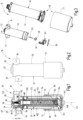
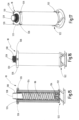
- the Fig. 1 to 3 show a filter device 10 according to the invention with a filter housing 12, which has at least two connection points 14, 16, such as an inlet 14 for unfiltered material and an outlet 16 for filtrate, and accommodates a replaceable filter element 18.
- the filter housing 12 is designed in two parts and has an upper housing part 20 and a lower housing part 22, which are screwed together via a thread 24 and sealed against each other by a seal 26.
- the inlet 14 and the outlet 16 are arranged in the area of a housing head 28 on opposite sides of the filter housing 12, wherein they have an axial offset V.
- At least one valve device 34 is provided which in an open position OS ( Fig. 10, 11 ) enables a fluid flow between one of the connection points 14, 16 and the filter element 18 and prevents this fluid flow in a closed position SS. Furthermore, the valve device 34 can be moved between the open position OS and the closed position SS by means of a control device 36, which comprises the housing lower part 22 and the filter element 18.
- Such a valve device 34 is an inflow valve 38, which is in the Fig. 1 and 3 to 14
- the inlet valve 38 is arranged in the fluid flow between the inlet 14 and an outer side 40 of the filter element 18 and has an inlet valve closing member 42 which is formed by a cylinder wall section 46 provided with an opening 44, which Fig. 6 to 9 shown and which is movably arranged in a semicircular slot 48 in the filter housing 12.
- the opening 44 of the cylinder wall section 46 is in the open position OS in overlap with a housing bore 50 of the inlet 14.
- the housing upper part 20 has the housing bore 50 on both sides of the slot 48, which enables a fluid flow from the inlet 14 into the interior 52 of the filter housing 12 in the open position OS of the inlet valve 38.
- the opening 44 in the cylinder wall section 46 has the shape of an elongated hole and is larger than the housing bore 50 of the inlet 14.
- the cylinder wall section 46 has the opening 44 in the side view ( Fig. 6 and 9 ) closer to its left end 54. Adjacent to the opening 44, on a bottom 56 of the cylinder wall portion 46, a pin 58 is provided which is inserted into a hole 60 in a plate part 62.
- the plate part 62 has several, preferably kidney-shaped openings 64 for the fluid flow between the inlet 14 and the outside 40 of the filter element 18. Furthermore, the plate part 62 has a filter element socket 68 on its underside 66, into which the filter element 18 can be screwed. An internal thread 70 is provided for this purpose. As can be seen in the Fig. 8 and 9 As can be seen, the filter element socket 68 is supported by stiffening struts 74 relative to a flange 72 of the plate part 62. The stiffening struts 74 are arranged offset on a pitch circle and reinforce a web 76 between the ends of the openings 64 of the plate part 62.
- the plate part 62 On the upper side 78, the plate part 62 has a filter housing socket 80, which has a circumferential groove 82 on the outer circumference, in which a sealing ring 84 is provided for sealing the plate part 62 relative to a receiving socket 86 arranged in the filter housing 12.
- a sealing ring 84 is provided for sealing the plate part 62 relative to a receiving socket 86 arranged in the filter housing 12.
- the plate part 62 in the filter housing 12 is placed against the receiving socket 86 and is held on the underside 66 by a snap ring 90 which is inserted into a circumferential groove 92 in the filter housing 12.
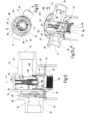
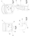
- a further valve device 34 is a drain valve 94, which is arranged in the fluid flow between an inner side 96 of the filter element 18 and the outlet 16 and has a spherical segment-shaped drain valve closing member 98, which comes into sealing contact with a stop 100 on the filter housing connector 80 of the plate part 62 and is urged into the closed position SS by a spring 102.
- the spring 102 is guided at the rear through a mandrel 104 of the filter housing 12.
- the drain valve closing member 98 has a central bore 106, into which the mandrel 104 can be inserted depending on the position of the drain valve closing member 98, as can be seen in particular in the Fig. 10 and 11 can be seen.
- the drain valve closing member 98 has a guide sleeve 107 which projects axially in the direction of the mandrel 104 and which rests against an outer side 108 of the spring 102.
- the drain valve closing member 98 also has a stop sleeve 110 for the spring 102.
- it is made of a material other than the guide sleeve 106 and the stop sleeve 110 as well as a stiffener 111 ( Fig. 13 ) hollow.
- the drain valve closing member 98 is in a cylindrical cavity 112 of the filter housing 12.
- the drain 16 extends in the radial direction away from this cavity 112.
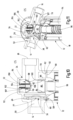
- the filter device 10 is shown with the valve devices 34 in the respective open position OS. It can be seen that the opening 44 of the cylinder wall section 46 of the inlet valve 38 is in overlap with the bore 50 of the inlet 14. The cylinder wall section 46 was rotated into this position when the filter element 18 was screwed into the plate part 62. Due to the resistance of the cylinder wall section 46, the open position OS is only reached when the filter element 18 is already completely screwed into the plate part 62.
- the unfiltered liquid flows from the inlet 14 through the inlet valve 38 and the kidney-shaped openings 64 in the flange 72 of the plate part 62 to the outside 40 of the filter element 18, through a filter medium 114 of the filter element 18 to its inside 96 and from there filtered through the central opening 116 of the plate part 62 to the drain valve 94. If the pressure is sufficiently strong, the drain valve closing member 98 is lifted off its valve seat 100 and the filtered liquid can flow to the drain 16.
- the filter device 10 with the valve devices 34 is shown in the closed position SS.
- the connection from the inlet 14 to the interior 102 of the filter housing 12 is interrupted by the cylinder wall section 46.
- the drain valve closing member 98 also rests on its valve seat 100. If the housing lower part 22 is unscrewed from the housing upper part 20, the filter element 18 is also rotated. Due to the screw connection of the filter element 18 and the plate part 62, the plate part 62 and the cylinder wall section 46 are also initially rotated until the cylinder wall section 46 at one end 118 ( Fig. 4 ) of its housing slot 48. Only then is the filter element 18 unscrewed from the plate part 62. Only after the filter element 18 has been completely unscrewed from the plate part 62 can the lower housing part 22 be completely unscrewed from the upper housing part 20.
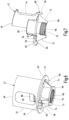
- the filter element 18 has the filter medium 114, which is arranged between an upper end cap 120 and a lower end cap 122 and is enclosed by them.
- a cylindrical support tube 124 is provided on an inner side 96 of the filter medium 114.
- the upper end cap 120 has four projections 126 on the circumference, which are evenly offset on a pitch circle and are intended to facilitate the handling of the filter element 18 when pulling it off the housing base 22.
- a threaded connector 128 with an external thread 130 is provided on the upper end cap 120, which Fig. 18 and 19 is shown in more detail.
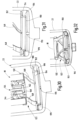
- the lower end cap 122 of the filter element 18 is made of several parts, with a border ring 132 enclosing the filter element 18 and holding a bypass valve 134.
- a fastening ring 150 is connected to this edging ring 132 via four S-shaped spring bands 148.
- the fastening ring 150 has a larger Diameter than the edging ring 132.
- the fastening ring 150 can be inserted into the housing base 22 and fastened there in a locking manner.
- the fastening ring 150 has a flange 152 and a connecting piece 154 extending axially downwards from the flange 152.
- the connecting piece 154 is provided on the outside with a locking collar 156, by means of which the filter element 18 can be releasably secured in the housing base 22 in a recess 158, which has an inwardly drawn-in locking piece 162 at an upper end 160.
- drivers 164 are arranged on the flange 152 - also evenly offset on a pitch circle - which have inclined surfaces 166 and vertically extending contact surfaces 168 which can engage with rotating parts 170 on the housing base 22.
- the rotating parts 170 are in the Fig. 26 to 29 and also have a shape with an inclined surface 172 and a vertical surface 174, so that the drivers 164 and the rotating parts 170 can slide along one another in a clockwise direction of rotation of the housing lower part 22 when screwing it on and engage when rotating in the anti-clockwise direction of unscrewing.
- the lower housing part 22 is secured to the main housing part 20 via the thread 24.
- the filter element 18 has the additional thread 130 so that it can be attached to the plate part 62.
- the thread pitches of these two threads 24, 130 differ to ensure that when the lower housing part 22 is unscrewed, the filter element 18 is first unscrewed from the plate part 62 before it is unscrewed from the upper housing part 20 together with the lower housing part 22.
- the spring elements 148 between the lower end cap parts 132, 150 are provided to enable length compensation. When screwing in the filter element 18, the procedure is reversed. First, the spring element 148 is screwed into the plate part 62 and then the lower housing part 22 is finally screwed onto the upper housing part 20.
- the filter housing 12, the filter element 18, the plate part 62 and the drain valve 98 are arranged coaxially to the longitudinal axis LA.
- the filter element 18 in the filter housing 12 is also rotated.
- the plate part 62 is also rotated together with the inflow valve closing element 46 until it comes to rest on one end 118 of the housing slot 48. This contact prevents the plate part 62 from being rotated any further.
- the spring elements 148 spring in and thus enable length compensation.
- the housing lower part 22 is then completely unscrewed from the housing upper part 20, with the filter element 18 remaining fastened to the housing lower part 22 in a locking manner. Finally, the filter element 18 can be removed from the housing base 22 and replaced with a new filter element 18.
- the filter device 10 shows a solution for effectively separating an interior 102 of a filter housing 12 from an inlet 14 and an outlet 16 by means of valve devices 34 when the filter housing 12 is unscrewed in order to replace the filter element 18. This has no equivalent in the prior art.
- the filter device 10 can be arranged at an angle to the vertical.
Landscapes
- Chemical & Material Sciences (AREA)
- Chemical Kinetics & Catalysis (AREA)
- Filtration Of Liquid (AREA)
- Lubrication Details And Ventilation Of Internal Combustion Engines (AREA)
Claims (15)
- Installation de filtration comprenant une enveloppe (12) de filtre, qui a au moins deux points (14, 16) de raccordement, comme une arrivée (14) pour du non filtrat et une évacuation (16) pour du filtrat, et dans laquelle est logé un élément (18) de filtre remplaçable, dans laquelle il est prévu au moins un dispositif (34) de soupape, qui, dans une position (OS) d'ouverture, rend possible un flux de fluide entre l'un des points (14, 16) de raccordement et l'élément (18) de filtre et, dans une position (SS) de fermeture, interdit ce flux de fluide, et dans laquelle le dispositif (34) de soupape peut, au moyen d'un dispositif (36) de commande, passer entre la position (OS) d'ouverture et la position (SS) de fermeture, dans lequel le un dispositif (34) de soupape est une soupape (38) d'admission, caractérisée en ce que la soupape (38) d'admission est montée dans le flux de fluide entre l'arrivée (14) et une face (40) extérieure de l'élément (18) de filtre et a un élément (42) de fermeture de soupape d'admission, qui est formée par une partie (46) de paroi cylindrique, qui est pourvue d'une ouverture (44) et qui est montée mobile dans une fente (48) de l'enveloppe (12) du filtre ; et en ce que l'ouverture (44) est, dans la position (OS) d'ouverture, en recouvrement avec l'arrivée (14).
- Installation de filtration suivant la revendication 1, caractérisée en ce que l'ouverture (44) dans la partie (46) de paroi cylindrique a la forme d'une boutonnière.
- Installation de filtration suivant la revendication 1 ou 2, caractérisée en ce que la partie (46) de paroi cylindrique est fixée à une partie (62) de plaque, qui est disposée entre l'enveloppe (12) de filtre et l'élément (18) de filtre ; et en ce que la partie (46) de paroi cylindrique a, de préférence au moins un ergot (58), qui est inséré dans un trou (60) de la partie (62) de plaque.
- Installation de filtration suivant la revendication 3, caractérisée en ce que la partie (62) de plaque a plusieurs ouvertures (64), de préférence réniformes, pour le flux de fluide entre l'arrivée (14) et la face (40) extérieure de l'élément (18) de filtre.
- Installation de filtration suivant la revendication 3 ou 4, caractérisée en ce que la partie (62) de plaque a une première tubulure (68) d'élément de filtre, dans laquelle l'élément (18) de filtre peut être vissé.
- Installation de filtration suivant l'une des revendications 3 à 5, caractérisée en ce que la partie (62) de plaque a au moins une entretoise (74) de raidissement à la tubulure (68) de l'élément de filtre.
- Installation de filtration suivant l'une des revendications 3 à 6, caractérisée en ce que la partie (62) de plaque a une tubulure (80) d'enveloppe de filtre, qui a, de préférence, du côté du pourtour extérieur, une rainure (82) périphérique, dans laquelle une bague (84) d'étanchéité peut être mise pour rendre la partie (62) de plaque étanche vis-à-vis de l'enveloppe (12) de filtre.
- Installation de filtration suivant l'une des revendications 3 à 7, caractérisée en ce que la partie (62) de plaque est, sur une face (66) inférieure, fixée à l'enveloppe (12) de filtre par un jonc (90).
- Installation de filtration suivant l'une des revendications précédentes, caractérisée en ce qu'un autre dispositif (34) de soupape est une soupape (94) d'évacuation, qui est montée dans le flux de fluide entre une face (96) intérieure de l'élément (18) de filtre et l'évacuation (16) et qui a un élément (98) de fermeture de soupape d'évacuation, de préférence en forme de segment sphérique, qui vient en contact avec étanchéité avec une butée (100), en particulier à la tubulure (80) de l'enveloppe de filtre, et qui, dans la position (SS) de fermeture, est soumise à l'effet d'un ressort (102).
- Installation de filtration suivant la revendication 9, caractérisée en ce que le ressort (102) est guidé du côté arrière par un mandrin (104) de l'enveloppe (12) du filtre.
- Installation de filtration suivant la revendication 10, caractérisée en ce que l'élément (98) de fermeture de la soupape d'évacuation a un alésage (106) central, dans lequel le mandrin (104) peut être introduit en fonction de la position de l'élément (98) de fermeture de la soupape d'évacuation.
- Installation de filtration suivant l'une des revendications 9 à 11, caractérisée en ce que l'élément (98) de fermeture de la soupape d'évacuation a un manchon (107) de guidage en saillie axialement, qui s'applique à une face (108) extérieure du ressort (102).
- Installation de filtration suivant l'une des revendications 9 à 12, caractérisée en ce que l'élément (98) de fermeture de la soupape d'évacuation a un manchon (110) de butée pour le ressort (102).
- Installation de filtration suivant la revendication 12 ou 13, caractérisée en ce que l'élément (98) de fermeture de la soupape d'évacuation est creux jusqu'au manchon (107) de guidage et/ou le manchon (110) de butée.
- Installation de filtration suivant l'une des revendications 9 à 14, caractérisée en ce que l'élément (98) de fermeture de la soupape d'évacuation est montée mobile dans un espace (112) cylindrique creux de l'enveloppe (12) du filtre.
Applications Claiming Priority (2)
| Application Number | Priority Date | Filing Date | Title |
|---|---|---|---|
| DE102021002024.3A DE102021002024A1 (de) | 2021-04-17 | 2021-04-17 | Filtervorrichtung |
| PCT/EP2022/058358 WO2022218701A1 (fr) | 2021-04-17 | 2022-03-30 | Appareil de filtration |
Publications (3)
| Publication Number | Publication Date |
|---|---|
| EP4146366A1 EP4146366A1 (fr) | 2023-03-15 |
| EP4146366C0 EP4146366C0 (fr) | 2025-02-26 |
| EP4146366B1 true EP4146366B1 (fr) | 2025-02-26 |
Family
ID=81308298
Family Applications (1)
| Application Number | Title | Priority Date | Filing Date |
|---|---|---|---|
| EP22716426.6A Active EP4146366B1 (fr) | 2021-04-17 | 2022-03-30 | Appareil de filtration |
Country Status (3)
| Country | Link |
|---|---|
| EP (1) | EP4146366B1 (fr) |
| DE (1) | DE102021002024A1 (fr) |
| WO (1) | WO2022218701A1 (fr) |
Families Citing this family (2)
| Publication number | Priority date | Publication date | Assignee | Title |
|---|---|---|---|---|
| DE102023003101A1 (de) | 2023-07-18 | 2025-01-23 | Hydac Filtertechnik Gmbh | Filtervorrichtung und Filterelement |
| CN120626593B (zh) * | 2025-06-19 | 2025-12-30 | 上海创力集团股份有限公司 | 一种可调节吸油过滤器 |
Family Cites Families (7)
| Publication number | Priority date | Publication date | Assignee | Title |
|---|---|---|---|---|
| US3777889A (en) | 1972-04-05 | 1973-12-11 | Ecodyne Corp | Cartridge filter unit |
| US7293660B2 (en) | 2004-12-22 | 2007-11-13 | Koo Chang Lin | Filter assembly having a five-way valve |
| EP2340883B1 (fr) * | 2005-11-15 | 2018-01-10 | Donaldson Company, Inc. | Ensemble filtre a liquides |
| KR101206645B1 (ko) * | 2010-12-10 | 2012-11-29 | 웅진케미칼 주식회사 | 외부밸브 승강식 오토 셧오프밸브가 구비된 필터 조립체 |
| ITMI20111315A1 (it) * | 2011-07-15 | 2013-01-16 | Acl S R L | Apparecchiatura filtrante |
| DE102017011081B4 (de) * | 2016-12-09 | 2019-10-17 | Mann+Hummel Gmbh | Filtersystem, Verwendung des Filtersystems und Filterelement |
| DE102020004489A1 (de) | 2020-07-24 | 2022-01-27 | H Y D A C Filtertechnik GmbH | Filtervorrichtung |
-
2021
- 2021-04-17 DE DE102021002024.3A patent/DE102021002024A1/de not_active Withdrawn
-
2022
- 2022-03-30 EP EP22716426.6A patent/EP4146366B1/fr active Active
- 2022-03-30 WO PCT/EP2022/058358 patent/WO2022218701A1/fr not_active Ceased
Also Published As
| Publication number | Publication date |
|---|---|
| WO2022218701A1 (fr) | 2022-10-20 |
| EP4146366C0 (fr) | 2025-02-26 |
| DE102021002024A1 (de) | 2022-12-01 |
| EP4146366A1 (fr) | 2023-03-15 |
Similar Documents
| Publication | Publication Date | Title |
|---|---|---|
| EP0748646B1 (fr) | Filtre de liquide | |
| EP0692292B1 (fr) | Filtre à liquides | |
| DE3018158C2 (de) | Preßluftarmatur | |
| EP3213803B1 (fr) | Système de filtre | |
| WO2016198136A1 (fr) | Dispositif filtre | |
| DE19605425A1 (de) | Flüssigkeitsfilter mit Filterumgehungsventil und filterelementseitiger Dichtfläche | |
| DE29610290U1 (de) | Flüssigkeitsfilter | |
| EP4146366B1 (fr) | Appareil de filtration | |
| EP0715692B1 (fr) | Soupape de protection de pompe | |
| WO2017050412A1 (fr) | Dispositif de filtration comprenant un élément d'accouplement | |
| DE2528932C2 (de) | Filteranordnung | |
| DE102019108955A1 (de) | Filter mit einem Filtergehäuse aus zwei Filtergehäuseteilen und mit einem im Filtergehäuse auswechselbar angeordneten Filtereinsatz sowie Filtereinsatz für den Filter | |
| EP4357000B1 (fr) | Dispositif filtre | |
| DE3308070C2 (de) | Temperaturabhängig steuerbares Heizungsventil mit Voreinstellvorrichtung | |
| DE4330839C2 (de) | Filter für die Reinigung von Flüssigkeiten | |
| DE69824056T2 (de) | Fluidfilteranordnung | |
| DE602004012297T2 (de) | Rückspülbarer filter mit schleuderabreinigung | |
| EP4171781B1 (fr) | Dispositif de filtration comportant un élément filtrant | |
| EP2062633B1 (fr) | Dispositif de filtration avec un élément filtrant | |
| DE29922324U1 (de) | Flüssigkeitsfilter | |
| DE102014010007B4 (de) | Filtervorrichtung und Filterelemente | |
| DE102019108957A1 (de) | Filter mit einem Filtergehäuse, mit einem auswechselbaren Filtereinsatz und mit einem Dichtungsträger daran | |
| EP1866050B1 (fr) | Dispositif filtrant | |
| DE29917562U1 (de) | Fluidfilter mit einem montierbarem, zentralen Bauteil | |
| DE2632441A1 (de) | Vorrichtung zum filtern von fluiden, insbesondere fluessigkeiten |
Legal Events
| Date | Code | Title | Description |
|---|---|---|---|
| STAA | Information on the status of an ep patent application or granted ep patent |
Free format text: STATUS: UNKNOWN |
|
| STAA | Information on the status of an ep patent application or granted ep patent |
Free format text: STATUS: THE INTERNATIONAL PUBLICATION HAS BEEN MADE |
|
| PUAI | Public reference made under article 153(3) epc to a published international application that has entered the european phase |
Free format text: ORIGINAL CODE: 0009012 |
|
| STAA | Information on the status of an ep patent application or granted ep patent |
Free format text: STATUS: THE APPLICATION HAS BEEN PUBLISHED |
|
| AK | Designated contracting states |
Kind code of ref document: A1 Designated state(s): AL AT BE BG CH CY CZ DE DK EE ES FI FR GB GR HR HU IE IS IT LI LT LU LV MC MK MT NL NO PL PT RO RS SE SI SK SM TR |
|
| STAA | Information on the status of an ep patent application or granted ep patent |
Free format text: STATUS: REQUEST FOR EXAMINATION WAS MADE |
|
| 17P | Request for examination filed |
Effective date: 20230420 |
|
| RBV | Designated contracting states (corrected) |
Designated state(s): AL AT BE BG CH CY CZ DE DK EE ES FI FR GB GR HR HU IE IS IT LI LT LU LV MC MK MT NL NO PL PT RO RS SE SI SK SM TR |
|
| DAV | Request for validation of the european patent (deleted) | ||
| DAX | Request for extension of the european patent (deleted) | ||
| GRAP | Despatch of communication of intention to grant a patent |
Free format text: ORIGINAL CODE: EPIDOSNIGR1 |
|
| STAA | Information on the status of an ep patent application or granted ep patent |
Free format text: STATUS: GRANT OF PATENT IS INTENDED |
|
| INTG | Intention to grant announced |
Effective date: 20241202 |
|
| GRAS | Grant fee paid |
Free format text: ORIGINAL CODE: EPIDOSNIGR3 |
|
| GRAA | (expected) grant |
Free format text: ORIGINAL CODE: 0009210 |
|
| STAA | Information on the status of an ep patent application or granted ep patent |
Free format text: STATUS: THE PATENT HAS BEEN GRANTED |
|
| AK | Designated contracting states |
Kind code of ref document: B1 Designated state(s): AL AT BE BG CH CY CZ DE DK EE ES FI FR GB GR HR HU IE IS IT LI LT LU LV MC MK MT NL NO PL PT RO RS SE SI SK SM TR |
|
| REG | Reference to a national code |
Ref country code: GB Ref legal event code: FG4D Free format text: NOT ENGLISH |
|
| REG | Reference to a national code |
Ref country code: CH Ref legal event code: EP |
|
| REG | Reference to a national code |
Ref country code: DE Ref legal event code: R096 Ref document number: 502022003034 Country of ref document: DE |
|
| REG | Reference to a national code |
Ref country code: IE Ref legal event code: FG4D Free format text: LANGUAGE OF EP DOCUMENT: GERMAN |
|
| U01 | Request for unitary effect filed |
Effective date: 20250226 |
|
| U07 | Unitary effect registered |
Designated state(s): AT BE BG DE DK EE FI FR IT LT LU LV MT NL PT RO SE SI Effective date: 20250304 |
|
| PG25 | Lapsed in a contracting state [announced via postgrant information from national office to epo] |
Ref country code: RS Free format text: LAPSE BECAUSE OF FAILURE TO SUBMIT A TRANSLATION OF THE DESCRIPTION OR TO PAY THE FEE WITHIN THE PRESCRIBED TIME-LIMIT Effective date: 20250526 |
|
| PG25 | Lapsed in a contracting state [announced via postgrant information from national office to epo] |
Ref country code: PL Free format text: LAPSE BECAUSE OF FAILURE TO SUBMIT A TRANSLATION OF THE DESCRIPTION OR TO PAY THE FEE WITHIN THE PRESCRIBED TIME-LIMIT Effective date: 20250226 |
|
| U20 | Renewal fee for the european patent with unitary effect paid |
Year of fee payment: 4 Effective date: 20250604 |
|
| PG25 | Lapsed in a contracting state [announced via postgrant information from national office to epo] |
Ref country code: ES Free format text: LAPSE BECAUSE OF FAILURE TO SUBMIT A TRANSLATION OF THE DESCRIPTION OR TO PAY THE FEE WITHIN THE PRESCRIBED TIME-LIMIT Effective date: 20250226 |
|
| PG25 | Lapsed in a contracting state [announced via postgrant information from national office to epo] |
Ref country code: NO Free format text: LAPSE BECAUSE OF FAILURE TO SUBMIT A TRANSLATION OF THE DESCRIPTION OR TO PAY THE FEE WITHIN THE PRESCRIBED TIME-LIMIT Effective date: 20250526 Ref country code: IS Free format text: LAPSE BECAUSE OF FAILURE TO SUBMIT A TRANSLATION OF THE DESCRIPTION OR TO PAY THE FEE WITHIN THE PRESCRIBED TIME-LIMIT Effective date: 20250626 |
|
| PG25 | Lapsed in a contracting state [announced via postgrant information from national office to epo] |
Ref country code: HR Free format text: LAPSE BECAUSE OF FAILURE TO SUBMIT A TRANSLATION OF THE DESCRIPTION OR TO PAY THE FEE WITHIN THE PRESCRIBED TIME-LIMIT Effective date: 20250226 |
|
| PG25 | Lapsed in a contracting state [announced via postgrant information from national office to epo] |
Ref country code: GR Free format text: LAPSE BECAUSE OF FAILURE TO SUBMIT A TRANSLATION OF THE DESCRIPTION OR TO PAY THE FEE WITHIN THE PRESCRIBED TIME-LIMIT Effective date: 20250527 |
|
| PG25 | Lapsed in a contracting state [announced via postgrant information from national office to epo] |
Ref country code: SM Free format text: LAPSE BECAUSE OF FAILURE TO SUBMIT A TRANSLATION OF THE DESCRIPTION OR TO PAY THE FEE WITHIN THE PRESCRIBED TIME-LIMIT Effective date: 20250226 |
|
| PG25 | Lapsed in a contracting state [announced via postgrant information from national office to epo] |
Ref country code: CZ Free format text: LAPSE BECAUSE OF FAILURE TO SUBMIT A TRANSLATION OF THE DESCRIPTION OR TO PAY THE FEE WITHIN THE PRESCRIBED TIME-LIMIT Effective date: 20250226 |
|
| REG | Reference to a national code |
Ref country code: CH Ref legal event code: H13 Free format text: ST27 STATUS EVENT CODE: U-0-0-H10-H13 (AS PROVIDED BY THE NATIONAL OFFICE) Effective date: 20251023 |
|
| PG25 | Lapsed in a contracting state [announced via postgrant information from national office to epo] |
Ref country code: SK Free format text: LAPSE BECAUSE OF FAILURE TO SUBMIT A TRANSLATION OF THE DESCRIPTION OR TO PAY THE FEE WITHIN THE PRESCRIBED TIME-LIMIT Effective date: 20250226 |
|
| PG25 | Lapsed in a contracting state [announced via postgrant information from national office to epo] |
Ref country code: MC Free format text: LAPSE BECAUSE OF FAILURE TO SUBMIT A TRANSLATION OF THE DESCRIPTION OR TO PAY THE FEE WITHIN THE PRESCRIBED TIME-LIMIT Effective date: 20250226 |
|
| PLBE | No opposition filed within time limit |
Free format text: ORIGINAL CODE: 0009261 |
|
| STAA | Information on the status of an ep patent application or granted ep patent |
Free format text: STATUS: NO OPPOSITION FILED WITHIN TIME LIMIT |
|
| PG25 | Lapsed in a contracting state [announced via postgrant information from national office to epo] |
Ref country code: CH Free format text: LAPSE BECAUSE OF NON-PAYMENT OF DUE FEES Effective date: 20250331 |
|
| PG25 | Lapsed in a contracting state [announced via postgrant information from national office to epo] |
Ref country code: IE Free format text: LAPSE BECAUSE OF NON-PAYMENT OF DUE FEES Effective date: 20250330 |
|
| 26N | No opposition filed |
Effective date: 20251127 |
|
| PGFP | Annual fee paid to national office [announced via postgrant information from national office to epo] |
Ref country code: GB Payment date: 20260115 Year of fee payment: 5 |