EP4147618A1 - Multifunktionales kochgerät für den aussenbereich - Google Patents
Multifunktionales kochgerät für den aussenbereich Download PDFInfo
- Publication number
- EP4147618A1 EP4147618A1 EP22190985.6A EP22190985A EP4147618A1 EP 4147618 A1 EP4147618 A1 EP 4147618A1 EP 22190985 A EP22190985 A EP 22190985A EP 4147618 A1 EP4147618 A1 EP 4147618A1
- Authority
- EP
- European Patent Office
- Prior art keywords
- enclosure
- wall
- hearth
- sole
- horizontal
- Prior art date
- Legal status (The legal status is an assumption and is not a legal conclusion. Google has not performed a legal analysis and makes no representation as to the accuracy of the status listed.)
- Withdrawn
Links
Images

Classifications
-
- A—HUMAN NECESSITIES
- A47—FURNITURE; DOMESTIC ARTICLES OR APPLIANCES; COFFEE MILLS; SPICE MILLS; SUCTION CLEANERS IN GENERAL
- A47J—KITCHEN EQUIPMENT; COFFEE MILLS; SPICE MILLS; APPARATUS FOR MAKING BEVERAGES
- A47J37/00—Baking; Roasting; Grilling; Frying
- A47J37/06—Roasters; Grills; Sandwich grills
- A47J37/07—Roasting devices for outdoor use; Barbecues
- A47J37/0718—Roasting devices for outdoor use; Barbecues with vertical fire box
-
- A—HUMAN NECESSITIES
- A47—FURNITURE; DOMESTIC ARTICLES OR APPLIANCES; COFFEE MILLS; SPICE MILLS; SUCTION CLEANERS IN GENERAL
- A47J—KITCHEN EQUIPMENT; COFFEE MILLS; SPICE MILLS; APPARATUS FOR MAKING BEVERAGES
- A47J37/00—Baking; Roasting; Grilling; Frying
- A47J37/06—Roasters; Grills; Sandwich grills
- A47J37/07—Roasting devices for outdoor use; Barbecues
- A47J37/0704—Roasting devices for outdoor use; Barbecues with horizontal fire box
-
- A—HUMAN NECESSITIES
- A47—FURNITURE; DOMESTIC ARTICLES OR APPLIANCES; COFFEE MILLS; SPICE MILLS; SUCTION CLEANERS IN GENERAL
- A47J—KITCHEN EQUIPMENT; COFFEE MILLS; SPICE MILLS; APPARATUS FOR MAKING BEVERAGES
- A47J37/00—Baking; Roasting; Grilling; Frying
- A47J37/06—Roasters; Grills; Sandwich grills
- A47J37/07—Roasting devices for outdoor use; Barbecues
- A47J37/0759—Roasting devices for outdoor use; Barbecues constructed from refractory blocks
-
- A—HUMAN NECESSITIES
- A47—FURNITURE; DOMESTIC ARTICLES OR APPLIANCES; COFFEE MILLS; SPICE MILLS; SUCTION CLEANERS IN GENERAL
- A47J—KITCHEN EQUIPMENT; COFFEE MILLS; SPICE MILLS; APPARATUS FOR MAKING BEVERAGES
- A47J37/00—Baking; Roasting; Grilling; Frying
- A47J37/06—Roasters; Grills; Sandwich grills
- A47J37/07—Roasting devices for outdoor use; Barbecues
- A47J37/0786—Accessories
- A47J2037/0795—Adjustable food supports, e.g. for height adjustment
Definitions
- the invention relates to a multifunction cooking device for outdoor use comprising an enclosure.
- the device comprises a horizontal hearth and a vertical hearth capable of receiving solid fuels.
- the bottom of the hearth as well as the upper wall can accommodate food to be cooked.
- the device has several modes of use which can be used in combination: oven, pizza oven, grill, griddle.
- the document US20020020404 discloses a charcoal grill having a frame defining a combustion chamber for receiving charcoal and a cooking grate mounted on the frame and extending at least partially above the combustion chamber.
- An additional compartment is positioned vertically close to the cooking grid and has a lower end intended to open into the combustion chamber and interacting with a movable sealing means, and an upper filling end for the replenishment of charcoal from said additional compartment.
- This charcoal grill includes a horizontal hearth, a vertical hearth and a horizontal grill grate that can be moved to different heights between the left and right side walls. On the other hand, it does not include a closed enclosure allowing the device to be used as an oven, nor a plate for cooking food à la plancha.
- the document ITTV20110028 describes a barbecue comprising a metal body and covered with refractory materials, a support for supporting the body, the support being made of marble without wheels or of metal with removable wheels, and a removable metal hood.
- the metallic structure is in the form of an open box but does not constitute an enclosure. It is designed to contain refractory tiles that can be easily removed and replaced when worn.
- the vertical walls are also equipped with refractory tiles.
- a grate attached to the rear wall can hold solid fuels in a vertical fireplace.
- the document US4089258 describes a portable cooking unit with a gas heat source, arranged vertically for roasting food mounted on a spit.
- a modification combines the vertical radiant panel with a bed of radiant material arranged horizontally under the spindle and heated by an auxiliary gas burner.
- the enclosure may be closed and include a horizontal grill grate, and the walls may include refractory materials.
- the cooking unit includes openings to allow air circulation, but does not allow the evacuation of ashes. Finally, it is not suitable for the use of fuels other than gas, and therefore needs to be connected to a gas source, which involves constraints in terms of installation, size, and safety. .
- the document CH542619 describes a rotisserie that can have a vertical hearth and a horizontal hearth for burning solid fuels.
- the device further comprises a mechanism intended to vary the position of the suspended foodstuffs and therefore the heat which they receive.
- the document does not describe a closed enclosure making it possible to reduce heat losses.
- An upper box accommodates the mechanism for changing the position of the food to be cooked. This casing prevents direct contact between the hot air from the hearths and the upper external surface of the enclosure.
- these cooking methods would include cooking in the oven, on the grill, on the plancha, and more specifically in the pizza oven, that is to say in which the food is placed on the hearth made of refractory material and hot from an oven.
- Making these cooking methods available to the user by means of a single device would make it possible to reduce the number of devices that the user must have, and would reduce the maintenance of these devices as well as the size associated with their possible storage. .
- An object of the invention is to solve this problem by providing a modular and multifunction cooking device that can be used outdoors.
- the device according to the invention makes it possible to cook food in the oven, on the griddle, on the grill or in the pizza oven, and these different cooking modes can be used simultaneously.
- the device further comprises two hearths able to accommodate solid fuels, and an enclosure that can serve as a furnace.
- the enclosure can be closed and its inner surface is partially covered with refractory materials to reduce heat loss and therefore the amount of fuel needed to cook food in the oven.
- the first refractory material, the second refractory material, and the third refractory material can all be different from each other, or chosen from only two different refractory materials, or be all identical.
- the first refractory material covering the hearth, the second refractory material covering the rear wall, and the third refractory material covering the left side wall and the right side wall may be identical or different and chosen from the following alternatives: soapstone , steatite, refractory concrete, reconstituted stone, refractory brick.
- the first refractory material covering the hearth is preferably chosen from the following alternatives: refractory concrete, reconstituted stone, refractory brick;
- the second refractory material covering the rear wall is preferably chosen from the following alternatives: soapstone, steatite, refractory concrete, reconstituted stone, refractory brick;
- the third refractory material covering the left and right side walls is a material or a combination of materials chosen preferably from the following alternatives: refractory concrete, reconstituted stone, refractory brick.
- the sole of the cooking device is flat.
- the plancha has a flat surface suitable for cooking food of at least 400cm 2 and at least 20cm x 20cm, the plancha being advantageously made of a steel plate stainless steel having a thickness between 2 and 10mm.
- the at least one opening of the sole is closed by an element for closing the opening of the sole being for example a grid or a perforated plate, the at least one opening of the hearth closed by the hearth opening closing element being able to allow air to enter the enclosure and the exit of the ashes from the enclosure and to prevent incandescent embers from coming out of the enclosure.
- a height of the enclosure measured in the vertical direction and separating the horizontal floor from the horizontal and removable upper wall in the mounted position is advantageously between 10 and 70 cm, preferably between 15 and 50 cm, preferably between 20 and 40 cm, and the dimensions of the enclosure measured along the horizontal directions advantageously allow the insertion of a cooking dish having the shape of a right circular cylinder whose diameter is aligned with the horizontal direction and is between 20 and 150 cm, preferably between 30 and 70 cm, preferably between 40 and 65 cm.
- the invention further comprises a frame intended to hold the enclosure in a stable raised position such that the floor is horizontal and separated from the ground by a distance measured in the vertical direction of between 60 and 120 cm. , preferably between 70 and 80 cm.
- the first refractory material covering the floor (3) is advantageously chosen from the following alternatives: refractory concrete, reconstituted stone, refractory brick.
- the second refractory material covering the rear wall (6) is advantageously chosen from the following alternatives: soapstone, steatite, refractory concrete, reconstituted stone, refractory brick.
- the third refractory material covering the left (13) and right (14) side walls is a material or a combination of materials advantageously chosen from the following alternatives: refractory concrete, reconstituted stone, refractory brick.
- plancha is advantageously made of one of the following materials: cast iron, enamelled cast iron, steel, preferably stainless steel.
- the cooking device further comprises a removable solid front wall capable of closing the front opening of the enclosure when it is in the mounted position.
- the removable solid front wall can comprise a metal plate or a transparent pane capable of withstanding a temperature of at least 500° C., preferably at least 700° C.
- Fig. 1 is a perspective view of a first embodiment of a cooking device 1 according to the invention.
- the cooking device comprises an enclosure 2 which can be opened.
- the shape of the enclosure is substantially equal to that of a rectangular parallelepiped.
- the enclosure is defined by six walls completely surrounding a volume of the enclosure.
- the interior of the enclosure is visible because an upper wall 9 horizontal and removable is not shown, and a perforated front wall 16 is in the open position of the front opening of the enclosure.
- the use of the qualifiers 'horizontal' or 'vertical' to qualify a wall means that the normal to this wall is vertical or horizontal, respectively, that is to say parallel or perpendicular, respectively, to the direction the gravity of a place when the device according to the invention is mounted and installed in a manner suitable for use by a user in this place.
- the terms vertical and horizontal refer to elements of the device according to the invention when the latter is installed in a manner suitable for use, that is to say in a stable and such that the sole 3 is horizontal.
- the qualifiers 'front' or 'rear' designate a part of the cooking device which is located on the user's side or on the opposite side farther from the user, respectively.
- the enclosure comprises a horizontal sole 3 and able to accommodate a horizontal hearth 4.
- This sole is partially covered with a first refractory material, preferably reconstituted stone, preferably in a single piece.
- a first refractory material preferably reconstituted stone, preferably in a single piece.
- refractory materials are known for their resistance to heat and for their thermal inertia, and this is also the case for the refractory materials used in the present invention.
- the sole 3 is therefore able to constitute the sole of a hearth and to accommodate solid fuels, for example incandescent embers.
- the sole is able to accommodate food to be cooked such as a pizza.
- the first refractory material partially covering the hearth can be made from a single piece and therefore does not include any gap between separate pieces of said first refractory material.
- the sole comprises at least one opening of the sole 5 passing through a rear part of the sole.
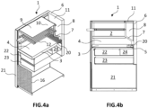
- the at least one opening of the sole 5 can be closed by a closing element of the opening of the sole 20 being for example a grid as illustrated in Fig. 4a and 4b .
- this grid may include metal bars with a diameter of 0.5 cm belonging to the same plane and spaced 2 cm apart.
- the at least one opening of the sole 5, when it is closed by the closing element of the opening of the sole 20, is able to allow the entry of air into the enclosure and the exit of the ashes. outside the enclosure and to prevent glowing embers from exiting the enclosure.
- the hearth can be entirely covered with the first refractory material except at the location of the opening of the hearth.
- the first refractory material covering the hearth may have an outer surface oriented towards the inside of enclosure 2 which is flat. This outer surface facing the inside of the enclosure 2 can also include protrusions or grooves whose height or depth, respectively, is measured in the vertical direction and is between 4 and 10 mm.
- the enclosure 2 also comprises a vertical rear wall 6 covered at least partially with a second refractory material, and preferably entirely covered with the second refractory material.
- the enclosure also comprises a left side wall 13 and a right side wall 14 which are vertical and covered at least partially with a third refractory material, and preferably completely covered with the third refractory material.
- the terms 'vertical rear wall', 'vertical left side wall', and 'vertical right side wall' mean that the normal to the surface of these walls is generally oriented in the horizontal direction. This does not exclude rear or left or right side walls slightly inclined or comprising non-vertical parts.
- the left 13 and right 14 side walls further comprise support means 15 which make it possible to maintain a grill grate 12 in a horizontal position and at different heights inside the enclosure 2.
- the grill grate 12 can also be positioned at the top of the enclosure.
- first refractory material designate one or more types of materials partially covering the hearth 3, the rear wall 6, and the left side wall 13 and the right side wall 14 , respectively.
- the first refractory material, the second refractory material, and the third refractory material may all be different from one another, or chosen from two different refractory materials, or all be identical.
- the first refractory material can be identical to the second refractory material and different from the third refractory material, or the first refractory material can be identical to the third refractory material and different from the second refractory material, or the second refractory material can be identical to the third refractory material and different from the first refractory material.
- the first, second, and third refractory materials can be selected independently of each other.
- the first refractory material covering the sole 3 is preferably chosen from the following alternatives: refractory concrete, reconstituted stone, refractory brick.
- the second refractory material covering the rear wall 6 is preferably chosen from the following alternatives soapstone, steatite, refractory concrete, reconstituted stone, refractory brick.
- the third refractory material covering the left 13 and right 14 side walls is a material or a combination of materials chosen preferably from the following alternatives: refractory concrete, reconstituted stone, refractory brick.
- the first refractory material covering the hearth 3, the second refractory material covering the rear wall 6, and the third refractory material covering the left side wall 13 and the right side wall 14, can be identical or different and chosen from the alternatives following: soapstone, steatite, refractory concrete, reconstituted stone, refractory brick.
- the first refractory material covering the hearth 3 is preferably chosen from the following alternatives: refractory concrete, reconstituted stone, refractory brick;
- the second refractory material covering the rear wall 6 is preferably chosen from the following alternatives: soapstone, steatite, refractory concrete, reconstituted stone, refractory brick;
- the third refractory material covering the left 13 and right 14 side walls is a material or a combination of materials chosen preferably from the following alternatives: refractory concrete, reconstituted stone, refractory brick.
- the refractory material has sufficient mechanical properties, it may be the sole material constituting the wall. The manufacture of the device is then simplified thanks to the reduced number of elements to be assembled.
- the refractory materials covering the walls can be held in place by means of a metallic structure.
- the use of refractory materials in the present invention makes it possible to increase the thermal resistance of the walls covered with a refractory material. This makes it possible to reduce the temperature of the outer surfaces of the walls of the device, which positively impacts the safety of the cooking device.
- the use of refractory materials reduces the heat losses through the walls and therefore the associated fuel consumption.
- the enclosure 2 also includes a vertical hearth grate 7 located in the rear part of the enclosure, as illustrated in Fig. 4a and 4b .
- the vertical hearth grate 7 is capable of retaining solid fuels and incandescent embers in a vertical hearth 8 located inside the enclosure and above at least part of the opening of the hearth 5.
- the vertical hearth 8 formed by the vertical hearth grate 7 may be located entirely above the hearth opening 5.
- the meaning of the term 'above' is as follows.
- the vertical hearth 8 is above the opening of the hearth because, when the cooking device according to the invention is installed in such a way that the hearth 3 is horizontal, there is a vertical axis which crosses both the hearth vertical and the opening of the hearth, and at least a part of the ash which falls by gravity from the vertical hearth goes towards the opening of the hearth. Ashes from the vertical hearth 8 can therefore leave the vertical hearth and fall by gravity towards the opening of the hearth 5. By falling by gravity, the ashes can then leave the enclosure by crossing the opening of the floor 5 preferably closed by the closing element of the opening of the floor 20.
- the vertical hearth grate 7 can have different shapes. It can for example be in the form of a tray and alone form a container capable of receiving and containing embers from the vertical hearth.
- the vertical hearth grate may for example be a wall defining a container in association with the vertical rear wall 6, as in the case of the first embodiment of the device according to the invention illustrated in Fig. 4a and 4b .
- the vertical hearth is contained between the vertical hearth grate 7 and the rear wall 6 and possibly part of the side walls.
- the vertical hearth grate can for example be a wall defining a container in association with the rear wall 6 and with the opening of the sole 5 closed by the closing element of the sole 20.
- the hearth closing element 20 prevents the embers of the vertical hearth from leaving the enclosure
- the vertical hearth grate 7 prevents the embers belonging to the vertical hearth from leaving the vertical hearth towards the rest of the enclosure 2.
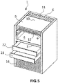
- the cooking device according to the invention may comprise a first drawer 22 located below the enclosure. This is illustrated in Fig. 4a and 4b And 5 .
- the first drawer comprises a compartment which constitutes an ash tray 24.
- the ash tray 24 is located below the opening of the floor 5 and is able to receive and contain the ashes passing through the hearth opening 5 and preferably the hearth opening closing element 20 by the effect of gravity.
- the enclosure therefore comprises a horizontal focus 4 and a vertical focus 8 which can be used simultaneously or separately depending on requirements.
- These two hearths are suitable for accommodating solid fuels including incandescent embers and the combustion of which produces ashes, for example wood or charcoal.
- the enclosure 2 also includes a horizontal and removable grill grate 12, i.e. the grill grate can be removed from the enclosure, and it can be placed at different heights inside the enclosure thanks to support means 15.
- the grill grate is able to receive food to be cooked and to hold it above the horizontal hearth and/or close to the vertical hearth.
- the height of the grill grate 12 is relative to the sole, that is to say it designates the distance measured in the vertical direction and separating the horizontal sole 3 from the grill grate positioned horizontally. inside the enclosure.
- the enclosure 2 can also include an optional grill grid which is vertical and removable and capable of maintaining food to be cooked inside the enclosure close to the vertical hearth 8 when the latter is in use.
- an optional grill grid which is vertical and removable and capable of maintaining food to be cooked inside the enclosure close to the vertical hearth 8 when the latter is in use.
- the optional Vertical Grill Rack allows more food to be placed closer to the vertical hearth.
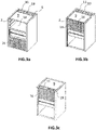
- FIG. 3b is a bird's eye perspective view of the first embodiment of the cooking device 1 according to the invention, in which the horizontal and removable upper wall 9 is in the mounted position, and in which the perforated front wall 16 is in the closed position of the front opening of the enclosure 18.
- the upper wall 9 is horizontal and located above the sole 3.
- all the walls and the sole then form an enclosure, it is that is to say that they completely surround an interior volume of the enclosure and prevent access to said volume of the enclosure except at the location of the openings of the sole 5 and of the upper wall 11 and at the location of the days of the perforated front wall 16.
- the openings of the perforated front wall 16 can allow the user to observe the combustion of solid fuels and the cooking of food inside the enclosure.
- the upper wall 9 of the cooking device according to the invention comprises a griddle 10 and an opening of the upper wall 11 allowing the exchange of air between the interior and the exterior of the enclosure 2.
- the upper walls 9 comprise a plancha 10, which means that at least part of the surface of the upper wall is suitable for accommodating food in order to cook it according to the plancha method.
- plancha cooking consists of cooking food directly on a heated, flat, and often metallic surface.
- the plancha 10 is advantageously made of a material chosen from the following: cast iron, enamelled cast iron, steel, preferably stainless steel.
- the entire upper wall 9 of the cooking device according to the invention can be a plancha, except at the location of the opening of the upper wall 11.
- the plancha can have a flat and suitable surface. for cooking food of at least 400cm 2 and at least 20cm by at least 20cm, and is made of a stainless steel plate having a thickness between 2 and 10mm.
- the thickness of the plancha plate is a compromise between two objectives which are, on the one hand, obtaining a uniform temperature over the entire surface of the plancha which is favored by an increase in the thickness of a plate constituting the plancha in order to increase the heat transfers within the plate of the plancha, and on the other hand, the easy handling by the user of the upper wall 9 comprising the plate of the plancha which is favored by a reduction in the thickness of the plate of the plancha in order to reduce the total weight of the upper wall 9.
- the upper wall 6 is advantageously able to be placed in two positions depending on the desired cooking mode.
- a first position of the upper wall illustrated in Fig. 3b the opening of the upper wall 11 is adjacent to the vertical hearth, that is to say that it is located above the vertical hearth 8, at the rear of the cooking device.
- the fumes given off by the combustion of the fuels in the enclosure are evacuated through the rear of the device.
- a second position of the upper wall illustrated in Fig. 3c the opening of the upper wall 11 is adjacent to the front opening of the enclosure.
- the opening of the upper wall 11 is located at the front of the cooking device and the fumes given off by the combustion of the fuels in the enclosure are evacuated from the front side of the device.
- the top wall opening 11 may be closed by a top wall closure member 19 that is removable and separable from the top wall 11.
- the top wall closure member 19 may include openings .
- the closing element of the upper wall 19 can for example be a grid, a perforated plate, or a continuous plate.
- the enclosure of the cooking device according to the invention also comprises a perforated front wall 16. This can be moved between two positions in order to open or close a front opening of the enclosure 18. For example, it can be moved in translation or by means of hinges.
- the opening and closing positions of the front opening of the enclosure are illustrated in Fig. 3a and 3b , respectively.
- the perforated front wall 16 can pass from the open position to the closed position by translation in the plane of the front opening of the enclosure 18.
- the translation movement is imposed by lateral slides surrounding at least part of the edges of the perforated front wall 16.
- These side rails are integral with the left 13 and right 14 side walls. -this is used in oven mode. The fuel is then used more efficiently.
- the perforated front wall has openings which are small holes or openings of small dimensions.
- the openings can have a circular shape and have a diameter of between 1 and 10 mm.
- the surface density of the openings on the total surface of the perforated front wall 16 is between 1 and 90%, preferably between 25 and 75%.
- the front opening of the enclosure 18 is located on the front face of the cooking device. As shown in Fig. 3a , access to the bottom of the cooking device according to the first embodiment of the invention is easy. When the perforated front wall 16 is in the open position of the front opening of the enclosure 18, the front opening of the enclosure is completely free.
- the sole and the surface of the refractory material partially covering the sole can be flat, which facilitates access to food cooked on the sole, in particular for the user who handles a pizza by means of a shovel. pizza. This is not the case when the sole is not flat and has the shape of a hollow container as in the majority of the devices of the prior art such as the devices described in US20020020404 And CH542619 .
- the hollow characteristic of the container induces the presence of substantially vertical edges which prevent direct access to the bottom of the container with a utensil. In this case, the manipulation of a pizza which cooks on the hearth using a pizza shovel is difficult because of the presence of the edge of the container.
- a height of the enclosure measured in the vertical direction and separating the horizontal sole 3 from the horizontal and removable upper wall 9 in the mounted position is advantageously between 10 and 70 cm, preferably between 15 and 50 cm, preferably between 20 and 40 cm , and the dimensions of the enclosure measured along the horizontal directions advantageously allow the insertion of a cooking dish having the shape of a right circular cylinder whose diameter is aligned with the horizontal direction and is between 20 and 150 cm, preferably between 30 and 70 cm, preferably between 40 and 65 cm.
- the latter comprises a frame intended to raise the enclosure relative to the ground in order to allow a user in a standing position to comfortably access the enclosure.
- the sole 3 can be maintained in a stable raised position such that the sole 3 is horizontal and separated from the ground of the place where the cooking device is installed by a distance measured in the vertical direction of between 60 and 120 cm, of preferably between 70 and 80cm.
- the left 13 and right 14 side walls are extended to the ground so as to form the frame.
- the left and right side walls have a rectangular shape and are made of cast stone.
- the first embodiment of the cooking device according to the invention advantageously comprises a first drawer 22 comprising the ash pan 24, and a second drawer 23 capable of containing kitchen utensils and serving as storage space.
- the first and the second drawer are supported by the frame 21 and can be opened or closed by causing them to translate in the horizontal plane, as illustrated in Fig. 5 .
- the cooking device according to the invention may further comprise a solid front wall, that is to say a continuous front wall comprising no openings.
- the solid front wall is removable and able to close the front opening of the enclosure 18 when it is in the mounted position.
- the removable solid front wall can comprise a metal plate or a transparent pane capable of withstanding a temperature of at least 500° C., preferably at least 700° C.
- the assembly of the solid front wall makes it possible to reduce a total surface of the openings between the interior and the exterior of the enclosure 2, and therefore to better conserve the heat inside the enclosure and to reduce the quantity of fuel needed to cook food inside the enclosure.
- the cooking device according to the invention may comprise additional modules, for example a table positioned adjacent to the left side wall or to the right side wall, or a cabinet for storing kitchen utensils or dishes or a reserve of fuel, for example.
- the cooking device according to the invention can also comprise other complementary modules such as a lid and/or a protective cover intended to protect the device when not in use, to prevent corrosion of the device caused by bad weather or soiling caused by a deposit of dust, for example.
- An advantage of the invention resides in the provision of a single cooking device for cooking food according to four different cooking modes: on the grill, on the plancha, in the oven, and in the pizza oven.
- the invention proposes methods of using the device according to the invention to carry out the cooking of food according to these four modes.
- the devices of the prior art do not allow food to be cooked according to these four modes.
- the device according to the invention makes it possible to combine these cooking modes simultaneously.
- a first method of cooking is grilling, also called barbecue cooking.
- the upper wall 9 and the perforated front wall 16 are removed from the cooking device 1, as shown in Fig. 1 .
- the grill grate 12 is positioned horizontally inside the enclosure. Solid fuels can be installed in the horizontal hearth 4 on the hearth 3 and/or in the vertical hearth 8 located in the rear part of the enclosure.
- the grill grate 12 is positioned above the sole and accommodates food to be cooked. The food is cooked by the heat given off by the combustion of the fuels in the horizontal 4 and/or vertical 8 hearth.
- the horizontal and vertical hearths can be used according to need.
- the use of the horizontal hearth 4 alone ensures a good distribution of heat over the entire grill grate 12.
- the height of the grill grate 12 can be adjusted to the need for heat to cook the food and to the calorific power released by the combustion.
- the use of the vertical hearth 8 alone makes it possible to cook food, and in particular meat, in a healthier way for human health. Indeed, the fat that comes out of the meat during cooking forms drops that cross the grill and fall by gravity. If the horizontal hearth is lit, the fat falls and is burned by the fire, releasing compounds that are harmful to human health.
- the device according to the invention offers the possibility of cooking food installed on the grill grate using the vertical hearth alone. In this configuration, the grease emitted by the food during cooking can fall below the grill grate 12 without coming into contact with the embers or incandescent fuels, thus avoiding the appearance of flame and compounds harmful to human health. .
- the ashes from the horizontal hearth 4 can be easily evacuated by the user by pushing them towards the rear of the hearth 3 to reach the opening of the hearth 5, the ashes then being able to come out of the enclosure by crossing the opening of the hearth and being received in the ash pan 24.
- the vertical hearth 8 being preferably located above the opening of the hearth 5, the ashes coming from the vertical hearth 8 fall on the hearth 3 or preferably directly through the opening of the hearth 5 towards the outside of the enclosure, and preferably towards the ash pan 24.
- a second mode of cooking with the device according to the invention is plancha cooking which consists in cooking the food directly on a heated, flat and often metallic surface.
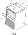
- This cooking method is for example shown in Fig. 2 .
- the upper wall which constitutes the cover is judiciously used to cook food à la plancha.
- the upper wall 9 in fact comprises a plancha 10.
- the device according to the invention thus allows an additional mode of cooking compared to the devices of the prior art without adding any additional part or mechanical part to the device, and without making the device complicated. use.
- the upper wall 9 is removable and can therefore easily be removed to clean the plancha 10.
- the plancha can constitute part of the upper wall, or preferably the entirety thereof except at the location of the opening of the upper wall 11.
- the plancha is suitable for cooking food according to the plancha method, which means that the plancha has a flat, horizontal cooking surface, and is devoid of paint or other compounds toxic to humans, and in particular is devoid toxic compounds for humans that could be released and settle on food when the griddle reaches temperatures ranging from 0°C to 500°C.
- the plancha can be heated using the heat given off by the combustion in the horizontal hearth 4.
- the user will preferably place the top wall 9 in the first position of the top wall in which the opening of the top wall 11 is adjacent to the vertical hearth 8 and the rear wall 6 of the enclosure 2. This allows the evacuation of smoke through the rear of the cooking device 1.
- the user will preferably place the perforated front wall 16 in the closed position of the front opening of the enclosure 18 in order to limit heat loss, as illustrated in Fig. 3b .
- the plancha can also be heated using the heat given off by the combustion in the vertical hearth 8.
- the user will preferably place the top wall 9 in the second position of the top wall in which the opening of the top wall is adjacent to the front opening of the enclosure 18.
- This position of the top wall 9 improves the transfer from the heat given off by the combustion within the vertical hearth to the upper wall 11 and to the griddle.
- the hot air resulting from the combustion within the vertical hearth passes through the enclosure and licks the surface of the upper wall 9 oriented towards the interior of the enclosure, thus heating the upper wall 9 by circulating from the part back to the front of the enclosure.
- the user can also place the perforated front wall 16 in the closed position of the front opening of the enclosure 18 in order to limit heat loss, as illustrated in Fig. 3c .
- the plancha cooking mode can be combined with the grill mode.
- the grill grate 12 accommodating food to be cooked can be inserted into the enclosure, while other foods can be cooked simultaneously on the plancha 10.
- cooking on the plancha 10 can also be done by simultaneously using the vertical and horizontal hearths.
- a third mode of cooking with the device according to the invention is the cooking of food in the oven, for example in a dish in the oven.
- the user who uses the horizontal hearth to produce the heat necessary for cooking food can preferably place the upper wall 9 in the first position of the upper wall so that the fumes escape through the rear of the device. .
- the user can preferably close the front opening of the enclosure 18 with the perforated front wall 16 or with the solid front wall, after having placed the dish inside the enclosure on the grill grate 12, above the horizontal focus.
- this oven mode with horizontal hearth it is still possible to simultaneously cook food on the plancha, and on the grill by means of a second grill grid able to accommodate food and positioned in the enclosure above or preferably above. below the grill rack 12 supporting the dish in the oven.
- Cooking food in the oven can also be done using the vertical hearth to produce heat.
- the user can place the top wall 9 in the second position of the top wall in order to force the hot air from the vertical hearth to pass through the enclosure.
- the user can preferably close the front opening of the enclosure 18 with the perforated front wall 16 or with the solid front wall, after having placed the dish inside the enclosure on the grill grate 12, or directly on the sole 3.
- the user can simultaneously cook food on the griddle 10, and on the grill, if necessary using a second grill grid able to accommodate food and positioned in the pregnant.
- the oven mode can be combined with the other cooking modes, which offers the user the advantage of being able to cook food preparations according to the different cooking modes without having to use different devices, preferably by switching on and maintaining a single focus.
- Preparing fire pit fuels in outdoor cooking devices is usually time consuming because it involves at least getting embers that produce sufficient heat for cooking while avoiding creating large flames that burn the outer surface of the stoves. food.
- Using a single cooking device is therefore advantageous in this respect because the number of devices and/or hearths to be managed simultaneously by the user is reduced.
- the presence of the oven cooking mode is particularly advantageous when it is necessary to keep foods warm that require different cooking times on the grill or the plancha. For example, foods that cook more quickly can be placed in a baking dish waiting to be eaten, while foods that cook more slowly finish cooking. When all the food has finished cooking, the user can then bring all the hot food to the table simultaneously, and eat at the same time as other guests without having to wait for the food which cooks more slowly to finish cooking.
- a fourth cooking mode with the device according to the invention is cooking in pizza oven mode.
- the user will preferably use the horizontal hearth initially, in order to heat the first refractory material partially covering the sole. Then, the solid fuels from the horizontal hearth can be moved into the vertical hearth, and the ashes from the horizontal hearth can be pushed to the rear of the hearth in order to fall into the ash pan through the hearth opening. Once the fuels and ashes have been removed from the hearth, the hearth can accommodate a pizza to be cooked.
- the user can then close the front opening of the enclosure 18 by means of the perforated front wall 16 or the solid front wall, and place the upper wall 9 in the mounted position, preferably in the second position of the upper wall , in order to close the enclosure to better conserve the heat inside it.
- the pizza then cooks thanks to the heat given off by the sole and by the fuels burning in the vertical hearth.
- the sole is flat, thus facilitating access to the sole with utensils and in particular with a pizza shovel.
- the perforated front wall 16 of the device according to the invention can be placed in the fully open position of the enclosure, which means that the entire front opening of the enclosure is then cleared.
- the sole being preferably flat, a pizza positioned horizontally and flat on the sole can be removed from the enclosure by causing the pizza to translate parallel to the surface of the sole in a horizontal plane and without modifying a vertical position of the pizza, the vertical position of the pizza being the distance separating the base of the pizza measured according to the vertical direction.
- the pizza oven cooking mode can be combined simultaneously with the plancha, oven and even grill cooking modes.
- other food can be placed on the grill grate above the pizza being cooked, in a pan and/or directly on the nearby grill grate of the vertical focus, respectively.
- REF DESCRIPTION 1 cooking device 2 Pregnant 3
- Sole 4 Horizontal focus 5
- Sole opening 6 Rear wall 7
- Upper wall 10 Griddle 11 Opening of the upper walls 12 grill grate 13 left side wall 14 Right side wall 15
- Closing element of the upper wall 20 Closing element of the hearth opening 21
Landscapes
- Engineering & Computer Science (AREA)
- Food Science & Technology (AREA)
- Baking, Grill, Roasting (AREA)
Applications Claiming Priority (1)
| Application Number | Priority Date | Filing Date | Title |
|---|---|---|---|
| BE20215719A BE1029752B1 (fr) | 2021-09-14 | 2021-09-14 | Dispositif de cuisson multifonction pour usage en exterieur |
Publications (1)
| Publication Number | Publication Date |
|---|---|
| EP4147618A1 true EP4147618A1 (de) | 2023-03-15 |
Family
ID=77801420
Family Applications (1)
| Application Number | Title | Priority Date | Filing Date |
|---|---|---|---|
| EP22190985.6A Withdrawn EP4147618A1 (de) | 2021-09-14 | 2022-08-18 | Multifunktionales kochgerät für den aussenbereich |
Country Status (2)
| Country | Link |
|---|---|
| EP (1) | EP4147618A1 (de) |
| BE (1) | BE1029752B1 (de) |
Citations (7)
| Publication number | Priority date | Publication date | Assignee | Title |
|---|---|---|---|---|
| CH542619A (fr) | 1971-09-22 | 1973-10-15 | Claire Montandon Andree | Rôtissoire |
| US4089258A (en) | 1975-08-29 | 1978-05-16 | Ducane Heating Corporation | Gas fired barbecue unit |
| US6000388A (en) * | 1998-11-12 | 1999-12-14 | Alphonso G. Andress | Barbecue grill with vertical hearth, rotisserie attachment, and/or pot rack |
| US6189526B1 (en) * | 1997-09-12 | 2001-02-20 | Springair 2000 Limited | Barbecue |
| US20020020404A1 (en) | 2000-08-03 | 2002-02-21 | Franck Viret | Charcoal grill with anti-flare |
| FR2991158A1 (fr) * | 2012-06-05 | 2013-12-06 | L Art Du Jardin | Ensemble de cuisson d'exterieur multifonction |
| FR3066885A1 (fr) * | 2017-06-06 | 2018-12-07 | L'art Du Jardin | Four d'exterieur a entree des flammes dans l'enceinte de cuisson |
-
2021
- 2021-09-14 BE BE20215719A patent/BE1029752B1/fr not_active IP Right Cessation
-
2022
- 2022-08-18 EP EP22190985.6A patent/EP4147618A1/de not_active Withdrawn
Patent Citations (7)
| Publication number | Priority date | Publication date | Assignee | Title |
|---|---|---|---|---|
| CH542619A (fr) | 1971-09-22 | 1973-10-15 | Claire Montandon Andree | Rôtissoire |
| US4089258A (en) | 1975-08-29 | 1978-05-16 | Ducane Heating Corporation | Gas fired barbecue unit |
| US6189526B1 (en) * | 1997-09-12 | 2001-02-20 | Springair 2000 Limited | Barbecue |
| US6000388A (en) * | 1998-11-12 | 1999-12-14 | Alphonso G. Andress | Barbecue grill with vertical hearth, rotisserie attachment, and/or pot rack |
| US20020020404A1 (en) | 2000-08-03 | 2002-02-21 | Franck Viret | Charcoal grill with anti-flare |
| FR2991158A1 (fr) * | 2012-06-05 | 2013-12-06 | L Art Du Jardin | Ensemble de cuisson d'exterieur multifonction |
| FR3066885A1 (fr) * | 2017-06-06 | 2018-12-07 | L'art Du Jardin | Four d'exterieur a entree des flammes dans l'enceinte de cuisson |
Also Published As
| Publication number | Publication date |
|---|---|
| BE1029752B1 (fr) | 2023-04-11 |
| BE1029752A1 (fr) | 2023-04-05 |
Similar Documents
| Publication | Publication Date | Title |
|---|---|---|
| EP2854611B1 (de) | Multifunktionelles kochgerät für den aussenbereich | |
| US6913011B1 (en) | Tapered grill, smoker and fireplace device | |
| US20170234546A1 (en) | Apparatus for cooking pizza in kettle- or kamado-style cooking grills | |
| EP1871205B1 (de) | Sicherheitsgrill mit doppelter vertikaler feuerkammer | |
| US20110219958A1 (en) | Multi-functional food preparation devices | |
| EP2648582B1 (de) | Grill- oder bratrostartige kochvorrichtung | |
| AU2011101304A4 (en) | Apparatus for cooking food products | |
| EP1868440B1 (de) | .vorrichtung zum backen von pizzas und grillen | |
| KR101997388B1 (ko) | 난로 겸용 구이기 | |
| FR2635258A1 (fr) | Combine barbecue - four a pizza portable | |
| FR3066885A1 (fr) | Four d'exterieur a entree des flammes dans l'enceinte de cuisson | |
| BE1029752B1 (fr) | Dispositif de cuisson multifonction pour usage en exterieur | |
| FR2828269A1 (fr) | Four a convexion directe | |
| JP3170738U (ja) | 焼き芋器 | |
| CN207613656U (zh) | 一种明火烤炉 | |
| FR2755503A1 (fr) | Four multifonctions | |
| FR2980094A1 (fr) | Barbecue ameliore permettant une cuisson saine et rapide des aliments | |
| FR3080527A1 (fr) | Barbecue a foyers verticaux et enceinte de cuisson a parois | |
| FR2894445A1 (fr) | Barbecue a foyer vertical | |
| US20220240720A1 (en) | Multifunction assemblable barbecue grill | |
| JP3492575B2 (ja) | グリル | |
| FR2757608A1 (fr) | Four multifonctions | |
| EP1072219A1 (de) | Barbecuegerät und Verfahren zum Herstellen eines solchen Geräts | |
| JP7274254B2 (ja) | 焼物器 | |
| EP3493725B1 (de) | Modularer grill mit integriertem kohlenpfannenofen |
Legal Events
| Date | Code | Title | Description |
|---|---|---|---|
| PUAI | Public reference made under article 153(3) epc to a published international application that has entered the european phase |
Free format text: ORIGINAL CODE: 0009012 |
|
| STAA | Information on the status of an ep patent application or granted ep patent |
Free format text: STATUS: THE APPLICATION HAS BEEN PUBLISHED |
|
| AK | Designated contracting states |
Kind code of ref document: A1 Designated state(s): AL AT BE BG CH CY CZ DE DK EE ES FI FR GB GR HR HU IE IS IT LI LT LU LV MC MK MT NL NO PL PT RO RS SE SI SK SM TR |
|
| STAA | Information on the status of an ep patent application or granted ep patent |
Free format text: STATUS: THE APPLICATION IS DEEMED TO BE WITHDRAWN |
|
| 18D | Application deemed to be withdrawn |
Effective date: 20230916 |