EP4148184A1 - Fondation pour supporter un poteau et agencement pour améliorer la sécurité liée à des structures de support pour un équipement routier - Google Patents
Fondation pour supporter un poteau et agencement pour améliorer la sécurité liée à des structures de support pour un équipement routier Download PDFInfo
- Publication number
- EP4148184A1 EP4148184A1 EP21195583.6A EP21195583A EP4148184A1 EP 4148184 A1 EP4148184 A1 EP 4148184A1 EP 21195583 A EP21195583 A EP 21195583A EP 4148184 A1 EP4148184 A1 EP 4148184A1
- Authority
- EP
- European Patent Office
- Prior art keywords
- foundation
- stiffening
- base
- post
- base plate
- Prior art date
- Legal status (The legal status is an assumption and is not a legal conclusion. Google has not performed a legal analysis and makes no representation as to the accuracy of the status listed.)
- Granted
Links
Images




Classifications
-
- E—FIXED CONSTRUCTIONS
- E01—CONSTRUCTION OF ROADS, RAILWAYS, OR BRIDGES
- E01F—ADDITIONAL WORK, SUCH AS EQUIPPING ROADS OR THE CONSTRUCTION OF PLATFORMS, HELICOPTER LANDING STAGES, SIGNS, SNOW FENCES, OR THE LIKE
- E01F9/00—Arrangement of road signs or traffic signals; Arrangements for enforcing caution
- E01F9/60—Upright bodies, e.g. marker posts or bollards; Supports for road signs
- E01F9/658—Upright bodies, e.g. marker posts or bollards; Supports for road signs characterised by means for fixing
- E01F9/673—Upright bodies, e.g. marker posts or bollards; Supports for road signs characterised by means for fixing for holding sign posts or the like
- E01F9/685—Subsoil means, e.g. foundations
-
- E—FIXED CONSTRUCTIONS
- E01—CONSTRUCTION OF ROADS, RAILWAYS, OR BRIDGES
- E01F—ADDITIONAL WORK, SUCH AS EQUIPPING ROADS OR THE CONSTRUCTION OF PLATFORMS, HELICOPTER LANDING STAGES, SIGNS, SNOW FENCES, OR THE LIKE
- E01F9/00—Arrangement of road signs or traffic signals; Arrangements for enforcing caution
- E01F9/60—Upright bodies, e.g. marker posts or bollards; Supports for road signs
- E01F9/623—Upright bodies, e.g. marker posts or bollards; Supports for road signs characterised by form or by structural features, e.g. for enabling displacement or deflection
- E01F9/631—Upright bodies, e.g. marker posts or bollards; Supports for road signs characterised by form or by structural features, e.g. for enabling displacement or deflection specially adapted for breaking, disengaging, collapsing or permanently deforming when deflected or displaced, e.g. by vehicle impact
Definitions
- the present invention relates generally to a foundation to be used for supporting a post, for example a road lighting post, a post for a road sign or the like. Further, the invention relates to an arrangement for improved safety in connection to support structures for road equipment, such as lighting posts, etc.
- the road equipment referred to in this application concern posts of different kind, which are attached to the ground by a foundation of metal.
- Foundations for supporting posts normally are made of concrete and have an elongate extension and a cross-section which may differ depending on the design (round, square, hexagonal, octagonal, square at the base and transient to octagonal at the top etc.).
- the European standard EN 12767 concerns a test method for road equipment and its support structures and specifies performance requirements and defines levels in passive safety to reduce the severity of injury to occupants of vehicles impacting head-on with the permanent road equipment support structures.
- the method is applicable to all types of support structure, but in practice, light posts and masts supporting signs are the most common applications. Collisions by vehicles with fixed objects starting at such low driving speed as 35-50 km/h and of course higher speed, entail a risk of fatal injury or permanent disability to car occupants.
- One option is to design the area around the road equipment to avoid any risk of impact, such as a stationary object can be protected with a road restraint system. This type unfortunately induces itself a risk.
- EN 12767 describes a method, based on a real impact test, which evaluates and classifies the effect of this weakening option.
- NE Non, Low or High Energy absorption.
- LE Non, Low or High Energy absorption.
- the support structure and the post may together contribute to the energy absorption such as the energy absorption is taken care of by the support structure (foundation) and the post together.
- the post may be allowed to leave the foundation and by that the post do not contribute to the total energy absorption. If the foundation more or less is arranged into the ground, i.e. not protruding enough above the ground surface to take up collision force, the NE-design do not contribute to absorb energy from the collision.
- the support structure should be a LE- or HE-classed structure.
- the posts which are to be supported by a foundation may be of different kinds. This application mainly concerns so-called soft posts for example suitable for road lighting purposes and the like.
- the Swedish patent SE 8503034-4 describes such post with a foundation of concrete for supporting the post.
- the post is a hollow post where the enclosing wall of the post is connected to rods to form a static unit to take care of stress forces, from wind or from a collision.
- the design of the post itself and the cooperation with the concrete foundation shall take care of the crash forces and, so to speak, bend/truckle in a controlled way, such as dampening the speed of the car and minimize possible injuries to the passengers in the car.
- Known posts like the one described above, are normally provided with a foot plate at their lower end, by means of which the post is attached to the foundation, but this plate, which normally is welded to both the wall and to the rods of the post, can have a negative effect on the post's ability to softly yield. This due to that the foot plate makes the solution too stiff.
- This solution comprises a foundation with a concrete body from which bolts project upwards in direction towards the post. These bolts are connected in pairs to each other at their top ends, and with their lower ends cast separately into the concrete body.
- the foot plate of a post is clamped to the rods with threaded sleeve or similar provided bolts by means of nuts arranged below and above the foot plate, like in SE 8503034-4 , but according to SE 8703896-1 , the foot plate is eliminated, and the rods of the post are directly connected to the bolts projecting from the concrete body of the foundation.
- the foot plate By eliminating the foot plate, the only remaining part of the post where it is not completely resilient is removed and upon the event of a collision, a soft force absorption is obtained right from the moment of impact until the vehicle is completely stopped. By that, the post can be flattened completely from the root end, whereby the foundation bolts also yield and participate in the force absorption while subjected to tensile stress. Regardless of whether the oncoming vehicle hits the post a bit up or - due to the ground conditions around the post - right at the lower end, the post will give way in the intended way.
- the cost of the post By not requiring a foot plate, the cost of the post can be reduced since the manufacture and attachment of the foot plate drives the cost and further, the fully open post at the bottom (no footplate) also facilitates the installation of cables for the power supply.
- a disadvantage with the above-described foundations is the use of concrete, both due to environmental reasons, working conditions during assembly of foundation and post as well as due to safety aspects.
- Production of concrete as well as transport of heavy foundations made of concrete drives the environmental impact on the planet and as a step towards using less carbon dioxide during production of posts and foundations, the applicant strives to eliminate concrete from their products.
- elimination concrete the applicant may deliver an "end product" directly to the construction site or customer, without the need of the extra step via a producer/manufacturer of concrete products, such as concrete foundations with integrated rods as described above. This also reduces transports and costs.
- a foundation which comprises a circumferential wall, enclosing an interior space, and a number of centering means arranged at the wall between an upper and lower end of the wall, and protruding in the radial direction, inwards into the interior space.
- the centering means are arranged to center an end portion of a post in the interior space and the foundation further comprises at adjusting means, arranged to adjust a post accommodated in the interior space relative the wall in the radial direction.
- EP20209741.6 The applicant's solution described in EP20209741.6 is very good since it eliminates the use of concrete, provides adjustment of the post when inserted into the foundation and provides high security. There is also a need of an alternative solution with a simpler and more cost-efficient design.
- connection to the post Another disadvantage with some types of known foundations and the connection to the post is that moisture may be trapped inside the hollow post since the connection of the post to the foundation is more or less sealed, for example by a connection plate or foot plate, or by that the post rest with its lower end on the top of the concrete foundation or a top cover. It is therefore a need to facilitate an arrangement which enables natural ventilation of the interior of the post, to increase the life span of the post.
- An object of the present invention is to provide a foundation for supporting a post for road equipment and an arrangement for improved safety in connection to support structures for road equipment, such as road lighting posts road signs or the like, wherein the foundation and the arrangement design meet the demands of the highest class HE in EN 12 767.
- a foundation which preferably is made of metal and is arranged for supporting a post in a substantially upright manner in a using position.
- the foundation is to be arranged into the ground and has an elongate extension direction which is similar with an axial direction of the post, in the using position, which position refers to when the post is supported by the foundation.
- the foundation comprises a base which comprises a base plate with an extent transverse the elongate extension direction of the foundation and which has a first area.
- the base further comprises at least one stiffening arrangement with an extent in the extension direction of the foundation and which has a second area, wherein the at least one stiffening arrangement extends a first distance, preferably upwards, from the base plate in the extension direction of the foundation, referring to the using position of the foundation.
- the base plate and the stiffening arrangement may be of different kinds.
- the base may be a flat plate, from which one or more plates protrudes, upwards or downwards, to facilitate a support for the base to avoid buckling and twisting or similar behavior, when the base is subjected to forces of different kinds.
- the stiffening arrangement may for example be a bent part of the base plate, along outer edges of the base plate or bent parts along slits arranged perpendicular to sides of the base plate, such as the stiffening parts points towards a center of the base plate.
- Other options may be a rectangular or circular sheet metal part which are welded to the base plate or for example protruding plates arranged as a cross and welded to the base plate.
- the base further comprises at least three elongate rods, each with a cross-sectional area, wherein each rod extends a first length upwards from the base plate in the elongate extension direction of the foundation.
- Each rod is fixedly connected with a first end either to the at least one stiffening arrangement or to the base plate, wherein each elongate rod is arranged at a second distance from another rod. The latter, to create a distance to adjacent rods such as an open space is achieved between the rods.
- each rod is arranged to be fixedly connected to the post with a second end which is distal from the first end of the rod.
- Such a solution first of all provides a solution without concrete. Secondly, the solution provides a controlled behavior in the event of a car crash to the post in the using position of the foundation when supporting the post, such as the highest class HE in EN 12 767 is achieved. This, due to that the base has a base plate with an extent transverse the elongate extension direction of the foundation such as an "anchor like" function is achieved. Further, the rods, whit their adapted cross-sectional area and length, are as mentioned fixedly attached to either the base plate or the stiffening arrangement, and by that transfer the crash force from the post to the base plate.
- the crash force that is the dimensioning force, even if most posts of course not are subjected to a car crash but only are subjected to wind forces.
- the length, dimension and number of rods, together with the dimensions (thickness, area, etc.) of the base plate and the dimensions (thickness, area, height, etc.) of the stiffening arrangement creates a resilient construction.
- the total performance and design of the foundation enables packing of soil material above and around the foundation. The total effect of the packed soil material together with the foundation enables a more controlled force absorption, whereby the foundation may yield in the packed soil.
- the soil material to be used is controlled by European standards, and normally consists of fractions of macadam with determined dimensions, and the packing of the macadam also is controlled by standardized methods.
- the concrete is so to speak replaced by packed macadam which allows better functionality compared to the concrete solution. This is a far better solution compared to prior art which takes care of the above-described problems.
- the first area of the base plate, the first length and the first cross-sectional area of the elongate rods and the second distance between adjacent rods are adapted to allow a determined volume of soil material, preferably normative packed macadam, to be packed on top of and above the base plate and around the rods, wherein the determined volume of packed soil material is determined by the first area of the base plate and at least 80-90% of the first length of the elongate rods minus the cross-sectional areas of the at least three elongate rods, wherein the foundation, together with the determined volume of packed soil material are arranged take care of a normative force conducted to the post transverse the extension direction of the post, when the post is fixedly connected to the foundation in the using position.
- a determined volume of soil material preferably normative packed macadam
- the first distance and the second area of the stiffening arrangement are adapted to allow fixation of the rods to the at least one stiffening plate and further adapted to transfer a force subjected to the post and transferred via the rods, further to the base plate.
- the stiffening arrangement also serves as a fixing arrangement for the rods as well as a stiffener to the base plate.
- the stiffening arrangement is at least one plate with the first height and a width to form the second area, wherein the area is adapted to transfer forces from the rods to the base plate and prevent buckling of the base plate, when the post and foundation are subjected to forces transverse the elongate extension of the foundation/post.
- the first and second ends of the at least three elongate rods comprise one of the following: a flat end portion, wherein the flat end portion preferably constitutes by flattened rod, or a slitted end portion which divides the end of the rod in two halves.
- a flattened end of the rod as well as a slitted end portion enable easy connection to the post as well as to the stiffening arrangement, especially since the post normally is hollow and if the stiffening arrangement has the form of a plate.
- each rod further comprises connecting means arranged in a position between the first and second ends of each rod (preferably near a top end of the rods) which are arranged to fixedly connect to a connection means of at least one other rod, preferably an adjacent rod.
- the connection means provides to set and adjust the second distance between the rods, at least to some extent, but also enable to fix the rods internally such as the foundation constitutes a coherent unit, with less possibility for the rods to bend during handling and transport and during assembly to the post.
- the base comprises four similar base parts fixedly connected to each other, wherein each base part is made of one single bent steel sheet metal, wherein each base part comprises the base plate from which at least one stiffening arrangement is bent such as the stiffening arrangement protrudes perpendicular upwards from the base plate in the extension direction along a first side of the base plate.
- each base part is made of one single bent steel sheet metal
- each base part comprises the base plate from which at least one stiffening arrangement is bent such as the stiffening arrangement protrudes perpendicular upwards from the base plate in the extension direction along a first side of the base plate.
- the four similar base parts are arranged as four "pieces of cake" arranged adjacent to each other and connected to each other to form a square base plate with upwardly protruding stiffening arrangements (i.e. upwardly bent steel sheet portions of the base plate).
- each of the four similar base parts mentioned above comprises two stiffening arrangement, wherein one stiffening arrangement is arranged along the first side of the base plate and the other stiffening arrangement is arranged along a second side of the base plate, wherein the four similar base parts are arranged such as the stiffening arrangements of one base part are positioned adjacent to stiffening arrangements of two other base parts, wherein the adjacent stiffening arrangements are fixedly connected to each other, to form the base.
- each base part comprises a triangular steel sheet metal base plate from which two portions of the steel sheet metal are bent upwards in the extension direction of the foundation, to form the two stiffening arrangements, wherein it is easy to fix the stiffening arrangements of two adjacent base parts to each other.
- the base plate of respective base part together forms a quadratic common base plate of the base of the foundation. This is a very robust and cost-effective solution for providing a HE-class foundation.
- the first end of each rod is fixedly connected to two adjacent stiffening arrangements of two adjacent base parts with fixation means, which fixation means thereby fixedly connects the first end of the rod to the stiffening arrangements as well as fixedly connects the two adjacent stiffening arrangements to each other.
- the base comprises two similar base parts fixedly connected to each other, wherein each base part is made of two parts: one bent steel sheet metal part, which comprises the base plate from which at least one first stiffening arrangement is bent, such as the first stiffening arrangement protrudes perpendicular upwards from the base plate in the extension direction along a first side of the base plate, and further at least one second stiffening plate, fixedly connected at least to the base plate of the bent steel sheet metal such as the second stiffening plate protrudes perpendicular upwards from the base plate of the bent steel sheet metal in the extension direction.
- one bent steel sheet metal part which comprises the base plate from which at least one first stiffening arrangement is bent, such as the first stiffening arrangement protrudes perpendicular upwards from the base plate in the extension direction along a first side of the base plate
- second stiffening plate fixedly connected at least to the base plate of the bent steel sheet metal such as the second stiffening plate protrudes perpendicular upwards from the base plate of the bent steel sheet metal in the
- the bent sheet metal part comprises a triangular base plate from which the first stiffening arrangement (first stiffening plate) is bent upwards along a first side of the triangular base plate, and the second stiffening plate may for example be welded to the base plate and preferably to the first stiffening arrangement (first stiffening plate), perpendicular relative the base plate and the first stiffening plate.
- first stiffening plate first stiffening plate
- second stiffening plate may for example be welded to the base plate and preferably to the first stiffening arrangement (first stiffening plate), perpendicular relative the base plate and the first stiffening plate.
- the two similar base parts are arranged such as the first stiffening arrangements of the two similar base parts are positioned adjacent to each other, wherein the adjacent stiffening arrangements are fixedly connected to each other, to form the base.
- two of the at least three rods are fixedly connected with their respective first end to the two first adjacent stiffening arrangements of the two adjacent base parts with fixation means, which fixation means thereby fixedly connects the first end of the rod to the first stiffening arrangements as well as fixedly connects the two adjacent first stiffening plates to each other.
- the rods are hollow.
- the total weight is lowered at the same time as the rod ends may be slitted or flattened in an easy and cost-efficient way.
- the stiffening arrangement comprises at least one first through hole arranged to receive a bolt.
- the at least one first through hole is elongate.
- An elongate through holes provides certain tolerance when positioning and fixing the rods to the stiffening arrangement.
- the first end of the respective elongate rod comprises at least one second through hole arranged to receive a bolt. This to enable fixation of the rod to the stiffening arrangement by means of a bolt and a nut.
- the second end of the respective elongate rod comprises at least one third through hole arranged to receive a bolt.
- the second end of the respective elongate rod further comprises a nut which is centered around the at least one third through hole and fixedly attached at the rod.
- an arrangement for improved safety in connection to support structures for road equipment comprises a post which at least at a lower end comprises a hollow cross-section, and further a foundation according to any of the preceding claims, which foundation is arranged for supporting the post in a substantially upright manner in a using position.
- the post further comprises a number of through holes at the lower end of the post, wherein each through hole is arranged to receive a bolt, for fixedly connection of the post to the rods of the foundation.
- No prior art provides a complete arrangement with the highest class HE in EN 12 767, without the use of concrete and which arrangement yields in a controlled manner by the design of the foundation in cooperation with packed soil, to achieve a controlled force absorption and thereby lower the speed of the vehicle, to avoid severe injuries of passengers of a vehicle.
- Fig. 1 shows a side view of an arrangement which has an improved safety concerning collision safety in the field of road equipment and its support structures.
- the arrangement comprises a post 100, which lower end is visible in the figure, and a foundation 1 which is arranged for supporting the post 100 in a substantially upright manner in a using position.
- the foundation 1 is to be arranged into the ground and has an elongate extension direction z which is similar with an axial direction of the post 100 in the using position of the foundation
- the foundation 1 comprises a base 10 arranged at a lower part of the foundation 1 seen in the using position when supporting the post 100.
- the base 10 comprises a base plate 11 with an extent transverse the elongate extension direction z of the foundation 1, such as forming a first area A.
- the base 10 further comprises at least one, but preferably four or eight stiffening arrangements 12, each with an extent in the extension direction z of the foundation 1.
- At least three, but preferably four elongate rods 20 extend a first length I upwards from the base plate 11 in the elongate extension direction z of the foundation 1, in the using position of the foundation 1.
- Each rod 20 is fixedly connected with a first end 21 of the rod 20 either to the stiffening arrangement 12 or to the base plate 11. In the preferred embodiment of Fig. 1 , the rods 20 are fixedly attached to the stiffening arrangement 12.
- the main function of the stiffening arrangement is to strengthen the base plate 11 to avoid buckling of the base plate 11 when the foundation is subjected to wind forces and crash forces during use, but as mentioned above, the fixation of the rods 20 to the stiffening arrangements 12 is another function which provides transformation of forces from the post 100, to the base plate 11 via the rods 20 and the stiffening arrangements 12.
- Each rod 20 is arranged to be fixedly connected to the post 100 with a second end 22 which is distal from the first end 21 of the rod 20, which may be seen in the upper part of the figure, where also a lower end of the upright post 100 may be seen.
- the rods 20 When the foundation 1 is "installed” into the ground, normally in an excavated pit, in a standardized way (according to standards within the field of road equipment), the rods 20 normally protrudes a bit above a ground surface 200. This will be explained further below.
- Fig. 2 shows a side view of the foundation 1 according to Fig. 1 with a determined volume V of packed soil material defined by the dimensions of the foundation.
- the first area A of the base plate 11, the first length I and a cross-sectional area of the elongate rods 20 and a second distance b between adjacent rods 20 are adapted such as allowing the determined volume V of soil material, preferably normative packed macadam (according to standards within the field), to be packed on top of and above the base plate 11 and around the rods 20.
- the determined volume V of packed soil material is determined by the first area A of the base plate 11 and at least 80-90% of the first length I of the elongate rods 20 minus the cross-sectional areas of the at least three elongate rods 20.
- the foundation 1 with its design together with the determined volume V of packed soil material are arranged take care of a normative force conducted to the post 100 transverse the extension direction z of the post 100, when the post 100 is fixedly connected to the foundation 1 in the using position.
- the base plate 11 functions as an anchor which is "fixed” in the packed macadam and the area A of the base plate 11 is adapted by its size such as the volume V is enough to take up the predetermined test force according to the standards. Further, the dimensions of the rods (length, cross-section) and the number of rods 20, are adapted to allow the determined volume V of packed macadam above the base plate 11, and the distance between the rods 20 further allows macadam to be packed around the rods 20 such as no "pockets" of air (gaps with no macadam) occurs in the volume. By this design, a body of concrete is avoided.
- the rods 20 may yield into the packed macadam wherein the foundation 1 gets a resilient behavior which is good when managing crash-forces.
- the volume V may also be slightly limited by the dimensions of the stiffening arrangements 12.
- the use of 80-90% of the first length I of the elongate rods 20 is preferred since the rods 20 preferably shall protrude above the ground surface 200, to allow ventilation of the post 100 and to make sure that rainwater and the like may leave the lower end of the post 100.
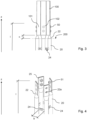
- Fig. 3 and 4 show a zoomed view of an upper part of the foundation 1 and in Fig. 3 a lower part of a post 100 is mounted to the foundation 1 but in Fig. 4 , the post is not attached to the rods 20.
- Each rod 20 has a cross-sectional area which is hollow and each rod 20 extends the first length I upwards from the base plate (not visible in Fig.3-4 ) in the elongate extension direction z of the foundation 1, as mentioned above.
- the second ends 22 ends a third distance c above the ground surface 200, to allow ventilation of the post 100 and to make sure that rainwater and the like may leave the lower end of the post 100 as discussed above.
- each rod 20 has a flat end portion 25 and each rod 20 is arranged to be fixedly connected to the post 100 with its respective second end 22 by means of bolt 50, wherein the second end 22 of the respective elongate rod 20 comprises third through holes 22a.
- the post 100 comprises a number of through holes 102 at the lower end of the post 100, which are arranged to receive a respective bolt 50, for fixedly connection of the post 100 to the rods 20.
- a nut 51 is preferably fixedly attached to insides of the flat end portion 25 of the second end 22 in a centered position relative the third through hole 22a.
- Each rod 20 is arranged at a second distance b from each other which may be selected depending on the size of the post (i.e. the diameter of the post).
- Each rod 20 further comprises connecting means 24 which are arranged in a position between the first and second ends 21, 22 of each rod 20, preferably near the second ends 22.
- the connecting means 24 are arranged to fixedly connect to a connection means 24 of at least one other adjacent rod 20.
- the connecting means 24 comprises a number of holes in different positions in which a rivet or the like may be introduced to fixedly connect the connecting means 24 to each other. By the number of holes of the connecting means 24 an adjustment of the second distance b, at least near the second ends 22 of the rods 20, is possible.
- Fig. 5a-c show an embodiment of the base 10 of the foundation 1.
- Fig. 5c shows an exploded view of the base 10 where four similar base parts 27 are mounted together to form one base 10.
- Fig 5b shows the base 10 of the foundation 1 of Fig. 5a where the four base parts 27 are mounted to each other and to four rods 20 and
- Fig. 5c shows the foundation 1 in a top view from above.
- each base part 27 is made of one single bent steel sheet metal, which comprises the base plate 11 from which two stiffening arrangements 12 are bent such as the stiffening arrangements 12 protrudes perpendicular upwards from the base plate 11, in the extension direction z, along a first side 11a and second side 11b of the base plate 11.
- Each stiffening arrangement 12 extends a first distance a from the base plate 11 in the extension direction z of the foundation 1 and has a second area B formed by the first distance a and a width.
- the first distance a and the second area B of the stiffening arrangement 12 are adapted to allow fixation of the rods 20 to stiffening plate 12 and further adapted to transfer a force subjected to the post 100, and which is transferred via the rods 20, further to the base plate 11 and to strengthen the base plate 11 to cope with the forces and to avoid buckling of the base plate 11.
- a complementary stiffening fold 12a is arranged along the outer edge of each base part 27.
- the area of the base plate 11 is about a quarter of the first area A (A/4).
- each stiffening arrangement 12 comprises at least one, but preferably two elongate, first through holes 13, each arranged to receive fixation means 29, for example a bolt or the like, which may be introduced into the first through hole 13.
- the first end 21 of the respective elongate rod 20 comprises at least one, but preferably two second through holes 21a which arranged to receive a bolt or the like.
- the four similar base parts 27 are arranged such as the stiffening arrangements 12 of one base part 27 are positioned adjacent to stiffening arrangements 12 of two adjacent base parts 27, wherein the adjacent stiffening arrangements 12 are fixedly connected to each other by means of the fixation means 29, to form the base 10. As seen in Fig.
- the first end 21 of each rod 20 has a flat end portion 25 which in this embodiment is introduced between two adjacent stiffening arrangements 12 and fixed between these by the fixation means 29.
- a very robust connection is achieved between the base parts 27 and the rod 20.
- the open design of the foundation 1 and the first area A of the base plate 11 allows as mentioned above macadam of predefined structure to be packed on top of the base plate 11 and around the rods 20, to gain the same and better functionality compared to concrete foundations.
- Fig.6a shows an exploded view of a base 10 of the foundation according to an alternative embodiment, where four similar base parts 27 are mounted together to form one base 10.
- Fig 6b shows the base 10 of the foundation of Fig. 6a where the four base parts 27 are mounted to each other and to a number of rods 20 according to the alternative embodiment.
- the main difference between this embodiment and the one described above is that the first end 21 of each rod 20 comprise a slitted end portion 26 which divides the first end 21 of the rod 20 in two halves.
- the first through holes 13 may be just round holes and not elongate but elongate first through holes 13 may also be used.
- Fig. 7 shows an exploded view of a base 10 of the foundation 1 according to an alternative embodiment, where two similar base parts 28 are mounted together to form one base 10.
- Each base part 28 is made of two parts 28a, 12b, one bent steel sheet metal part 28a and at least one second stiffening plate 12b.
- the bent steel sheet metal part 28a comprises the base plate 11 from which at least one, but preferably two first stiffening arrangements 12a are bent such as the first stiffening arrangements 12a protrude perpendicular upwards from the base plate 11 in the extension direction z along a first side 11a of the base plate 11.
- the second stiffening plate 12b is fixedly connected to the base plate 11 of the bent steel sheet metal 28a such as the second stiffening plate 12b protrudes perpendicular upwards from the base plate 11 of the bent steel sheet metal 28a in the extension direction z.
- the two similar base parts 28 are positioned adjacent to each other and are fixedly connected to each other to form the base 10.
- the two base parts 28 with their respective first stiffening arrangements 12a may be arranged in similar way like described above and fixed to each other by the fixation means 29.
- Fig. 7 the slitted version is shown.
- the respective first end 21 of at least two of the rods 20 may be connected to the two first adjacent stiffening arrangements 12a of the two adjacent base parts 28 with the fixation means 29, which thereby fixedly connects the first end 21 of the rod 20 to the first stiffening arrangements 12a as well as fixedly connects the two adjacent first stiffening plates 12a to each other to form the base 10.
- the other two rods 20 may be fixedly connected to the second stiffening plate 12b of respective two base parts 28.
- the base may for example one base plate from which one or more stiffening arrangements protrudes, and which is/are welded to the base plate or fixed in other ways to the base plate.
- the stiffening arrangements may for example be in the form of a pipe-like protruding circular shape, a quadratic or square form, triangular form, cross form etc.
Landscapes
- Engineering & Computer Science (AREA)
- Architecture (AREA)
- Civil Engineering (AREA)
- Structural Engineering (AREA)
- Foundations (AREA)
Priority Applications (2)
| Application Number | Priority Date | Filing Date | Title |
|---|---|---|---|
| EP21195583.6A EP4148184B1 (fr) | 2021-09-08 | 2021-09-08 | Fondation pour supporter un poteau et agencement pour améliorer la sécurité liée à des structures de support pour un équipement routier |
| PL21195583.6T PL4148184T3 (pl) | 2021-09-08 | 2021-09-08 | Fundament do podparcia słupa oraz układ do poprawy bezpieczeństwa w połączeniu z konstrukcjami wsporczymi dla sprzętu drogowego |
Applications Claiming Priority (1)
| Application Number | Priority Date | Filing Date | Title |
|---|---|---|---|
| EP21195583.6A EP4148184B1 (fr) | 2021-09-08 | 2021-09-08 | Fondation pour supporter un poteau et agencement pour améliorer la sécurité liée à des structures de support pour un équipement routier |
Publications (3)
| Publication Number | Publication Date |
|---|---|
| EP4148184A1 true EP4148184A1 (fr) | 2023-03-15 |
| EP4148184B1 EP4148184B1 (fr) | 2025-08-13 |
| EP4148184C0 EP4148184C0 (fr) | 2025-08-13 |
Family
ID=77951461
Family Applications (1)
| Application Number | Title | Priority Date | Filing Date |
|---|---|---|---|
| EP21195583.6A Active EP4148184B1 (fr) | 2021-09-08 | 2021-09-08 | Fondation pour supporter un poteau et agencement pour améliorer la sécurité liée à des structures de support pour un équipement routier |
Country Status (2)
| Country | Link |
|---|---|
| EP (1) | EP4148184B1 (fr) |
| PL (1) | PL4148184T3 (fr) |
Cited By (1)
| Publication number | Priority date | Publication date | Assignee | Title |
|---|---|---|---|---|
| EP4722452A1 (fr) * | 2024-10-01 | 2026-04-08 | AB Varmförzinkning | Fondation réglable pour supporter un poteau et agencement pour améliorer la sécurité sur un équipement routier |
Citations (4)
| Publication number | Priority date | Publication date | Assignee | Title |
|---|---|---|---|---|
| DE2442047A1 (de) * | 1973-09-12 | 1975-03-20 | Lars Svensson | Mastfundament |
| FR2350453A1 (fr) * | 1976-05-05 | 1977-12-02 | Dziewolski Richard | Pylones support de lignes electriques haute tension de forme pyramidale a base triangulaire en construction tubulaire ou profiles |
| JP2007126900A (ja) * | 2005-11-04 | 2007-05-24 | Chigawa Kenchiku Jimusho:Kk | 柱脚用独立基礎及びその施工方法 |
| KR20130066094A (ko) * | 2011-12-12 | 2013-06-20 | 이수익 | 구조물의 버팀대용 베이스체 |
-
2021
- 2021-09-08 PL PL21195583.6T patent/PL4148184T3/pl unknown
- 2021-09-08 EP EP21195583.6A patent/EP4148184B1/fr active Active
Patent Citations (4)
| Publication number | Priority date | Publication date | Assignee | Title |
|---|---|---|---|---|
| DE2442047A1 (de) * | 1973-09-12 | 1975-03-20 | Lars Svensson | Mastfundament |
| FR2350453A1 (fr) * | 1976-05-05 | 1977-12-02 | Dziewolski Richard | Pylones support de lignes electriques haute tension de forme pyramidale a base triangulaire en construction tubulaire ou profiles |
| JP2007126900A (ja) * | 2005-11-04 | 2007-05-24 | Chigawa Kenchiku Jimusho:Kk | 柱脚用独立基礎及びその施工方法 |
| KR20130066094A (ko) * | 2011-12-12 | 2013-06-20 | 이수익 | 구조물의 버팀대용 베이스체 |
Cited By (1)
| Publication number | Priority date | Publication date | Assignee | Title |
|---|---|---|---|---|
| EP4722452A1 (fr) * | 2024-10-01 | 2026-04-08 | AB Varmförzinkning | Fondation réglable pour supporter un poteau et agencement pour améliorer la sécurité sur un équipement routier |
Also Published As
| Publication number | Publication date |
|---|---|
| PL4148184T3 (pl) | 2025-12-22 |
| EP4148184B1 (fr) | 2025-08-13 |
| EP4148184C0 (fr) | 2025-08-13 |
Similar Documents
| Publication | Publication Date | Title |
|---|---|---|
| CA2465278C (fr) | Poteau de support flexible en acier pour glissiere de securite | |
| AU9711498A (en) | Highway barrier and guardrail | |
| US7052201B2 (en) | Safety bollard | |
| EP4148184B1 (fr) | Fondation pour supporter un poteau et agencement pour améliorer la sécurité liée à des structures de support pour un équipement routier | |
| KR101420587B1 (ko) | 가드레일판이 구비된 지주 보강구조 | |
| KR101358426B1 (ko) | 교통신호등 지주구조체 | |
| KR20120001028U (ko) | 높이 조절식 보강 가드레일 | |
| CN111648275A (zh) | 波形梁护栏加强方法及波形梁护栏 | |
| EP1191150B1 (fr) | Dispositif de passage temporaire pour terre-plein central | |
| US20070063179A1 (en) | A weakened guardrail mounting connection | |
| EP4083323B1 (fr) | Structure de support pour équipement routier | |
| EP1709250B1 (fr) | Poteau routier | |
| EP4722452A1 (fr) | Fondation réglable pour supporter un poteau et agencement pour améliorer la sécurité sur un équipement routier | |
| CN111065779A (zh) | 具有能量吸收层的电线杆 | |
| US20070063178A1 (en) | Guardrail flange protector | |
| WO2021080441A1 (fr) | Élément de montage | |
| CN210597123U (zh) | 一种城市道路用防撞吸能柱结构 | |
| EP0735194A2 (fr) | Poteau de sécurité et son procédé de construction | |
| JP2005201020A (ja) | 変形性防護柵 | |
| KR200228238Y1 (ko) | 도로 시설물용 충격흡수 기둥 | |
| US20070063177A1 (en) | Yielding post guardrail safety system | |
| AU785278B2 (en) | Utility pole | |
| CN209412756U (zh) | 一种市政道路施工的新型施工护栏 | |
| CN220133714U (zh) | 一种组合式立柱 | |
| CN217174495U (zh) | 一种分隔护栏定位连接结构 |
Legal Events
| Date | Code | Title | Description |
|---|---|---|---|
| PUAI | Public reference made under article 153(3) epc to a published international application that has entered the european phase |
Free format text: ORIGINAL CODE: 0009012 |
|
| STAA | Information on the status of an ep patent application or granted ep patent |
Free format text: STATUS: THE APPLICATION HAS BEEN PUBLISHED |
|
| AK | Designated contracting states |
Kind code of ref document: A1 Designated state(s): AL AT BE BG CH CY CZ DE DK EE ES FI FR GB GR HR HU IE IS IT LI LT LU LV MC MK MT NL NO PL PT RO RS SE SI SK SM TR |
|
| STAA | Information on the status of an ep patent application or granted ep patent |
Free format text: STATUS: REQUEST FOR EXAMINATION WAS MADE |
|
| 17P | Request for examination filed |
Effective date: 20230907 |
|
| RBV | Designated contracting states (corrected) |
Designated state(s): AL AT BE BG CH CY CZ DE DK EE ES FI FR GB GR HR HU IE IS IT LI LT LU LV MC MK MT NL NO PL PT RO RS SE SI SK SM TR |
|
| GRAP | Despatch of communication of intention to grant a patent |
Free format text: ORIGINAL CODE: EPIDOSNIGR1 |
|
| STAA | Information on the status of an ep patent application or granted ep patent |
Free format text: STATUS: GRANT OF PATENT IS INTENDED |
|
| INTG | Intention to grant announced |
Effective date: 20250318 |
|
| GRAS | Grant fee paid |
Free format text: ORIGINAL CODE: EPIDOSNIGR3 |
|
| GRAA | (expected) grant |
Free format text: ORIGINAL CODE: 0009210 |
|
| STAA | Information on the status of an ep patent application or granted ep patent |
Free format text: STATUS: THE PATENT HAS BEEN GRANTED |
|
| AK | Designated contracting states |
Kind code of ref document: B1 Designated state(s): AL AT BE BG CH CY CZ DE DK EE ES FI FR GB GR HR HU IE IS IT LI LT LU LV MC MK MT NL NO PL PT RO RS SE SI SK SM TR |
|
| REG | Reference to a national code |
Ref country code: GB Ref legal event code: FG4D |
|
| REG | Reference to a national code |
Ref country code: CH Ref legal event code: EP |
|
| REG | Reference to a national code |
Ref country code: DE Ref legal event code: R096 Ref document number: 602021035994 Country of ref document: DE |
|
| REG | Reference to a national code |
Ref country code: IE Ref legal event code: FG4D |
|
| U01 | Request for unitary effect filed |
Effective date: 20250909 |
|
| U07 | Unitary effect registered |
Designated state(s): AT BE BG DE DK EE FI FR IT LT LU LV MT NL PT RO SE SI Effective date: 20250915 |
|
| PGFP | Annual fee paid to national office [announced via postgrant information from national office to epo] |
Ref country code: AT Payment date: 20251020 Year of fee payment: 5 |
|
| U20 | Renewal fee for the european patent with unitary effect paid |
Year of fee payment: 5 Effective date: 20251117 |
|
| PG25 | Lapsed in a contracting state [announced via postgrant information from national office to epo] |
Ref country code: IS Free format text: LAPSE BECAUSE OF FAILURE TO SUBMIT A TRANSLATION OF THE DESCRIPTION OR TO PAY THE FEE WITHIN THE PRESCRIBED TIME-LIMIT Effective date: 20251213 |
|
| PGFP | Annual fee paid to national office [announced via postgrant information from national office to epo] |
Ref country code: GB Payment date: 20251117 Year of fee payment: 5 |
|
| PGFP | Annual fee paid to national office [announced via postgrant information from national office to epo] |
Ref country code: NO Payment date: 20251117 Year of fee payment: 5 |
|
| PG25 | Lapsed in a contracting state [announced via postgrant information from national office to epo] |
Ref country code: HR Free format text: LAPSE BECAUSE OF FAILURE TO SUBMIT A TRANSLATION OF THE DESCRIPTION OR TO PAY THE FEE WITHIN THE PRESCRIBED TIME-LIMIT Effective date: 20250813 |
|
| PG25 | Lapsed in a contracting state [announced via postgrant information from national office to epo] |
Ref country code: GR Free format text: LAPSE BECAUSE OF FAILURE TO SUBMIT A TRANSLATION OF THE DESCRIPTION OR TO PAY THE FEE WITHIN THE PRESCRIBED TIME-LIMIT Effective date: 20251114 |
|
| PGFP | Annual fee paid to national office [announced via postgrant information from national office to epo] |
Ref country code: PL Payment date: 20250918 Year of fee payment: 5 |
|
| PG25 | Lapsed in a contracting state [announced via postgrant information from national office to epo] |
Ref country code: RS Free format text: LAPSE BECAUSE OF FAILURE TO SUBMIT A TRANSLATION OF THE DESCRIPTION OR TO PAY THE FEE WITHIN THE PRESCRIBED TIME-LIMIT Effective date: 20251113 |
|
| PG25 | Lapsed in a contracting state [announced via postgrant information from national office to epo] |
Ref country code: ES Free format text: LAPSE BECAUSE OF FAILURE TO SUBMIT A TRANSLATION OF THE DESCRIPTION OR TO PAY THE FEE WITHIN THE PRESCRIBED TIME-LIMIT Effective date: 20250813 |
|
| PG25 | Lapsed in a contracting state [announced via postgrant information from national office to epo] |
Ref country code: SM Free format text: LAPSE BECAUSE OF FAILURE TO SUBMIT A TRANSLATION OF THE DESCRIPTION OR TO PAY THE FEE WITHIN THE PRESCRIBED TIME-LIMIT Effective date: 20250813 |
|
| PG25 | Lapsed in a contracting state [announced via postgrant information from national office to epo] |
Ref country code: CZ Free format text: LAPSE BECAUSE OF FAILURE TO SUBMIT A TRANSLATION OF THE DESCRIPTION OR TO PAY THE FEE WITHIN THE PRESCRIBED TIME-LIMIT Effective date: 20250813 |
|
| REG | Reference to a national code |
Ref country code: CH Ref legal event code: H13 Free format text: ST27 STATUS EVENT CODE: U-0-0-H10-H13 (AS PROVIDED BY THE NATIONAL OFFICE) Effective date: 20260425 |
|
| PG25 | Lapsed in a contracting state [announced via postgrant information from national office to epo] |
Ref country code: SK Free format text: LAPSE BECAUSE OF FAILURE TO SUBMIT A TRANSLATION OF THE DESCRIPTION OR TO PAY THE FEE WITHIN THE PRESCRIBED TIME-LIMIT Effective date: 20250813 |