EP4148237B1 - Mechanismus einer verstellbaren leitsschaufel, gastturbinentriebwerk und verfahren zum betrieb eines mechanismus einer verstellbaren leitsschaufel - Google Patents
Mechanismus einer verstellbaren leitsschaufel, gastturbinentriebwerk und verfahren zum betrieb eines mechanismus einer verstellbaren leitsschaufel Download PDFInfo
- Publication number
- EP4148237B1 EP4148237B1 EP22195227.8A EP22195227A EP4148237B1 EP 4148237 B1 EP4148237 B1 EP 4148237B1 EP 22195227 A EP22195227 A EP 22195227A EP 4148237 B1 EP4148237 B1 EP 4148237B1
- Authority
- EP
- European Patent Office
- Prior art keywords
- vane
- pin
- axis
- around
- main axis
- Prior art date
- Legal status (The legal status is an assumption and is not a legal conclusion. Google has not performed a legal analysis and makes no representation as to the accuracy of the status listed.)
- Active
Links
Images


Classifications
-
- F—MECHANICAL ENGINEERING; LIGHTING; HEATING; WEAPONS; BLASTING
- F01—MACHINES OR ENGINES IN GENERAL; ENGINE PLANTS IN GENERAL; STEAM ENGINES
- F01D—NON-POSITIVE DISPLACEMENT MACHINES OR ENGINES, e.g. STEAM TURBINES
- F01D17/00—Regulating or controlling by varying flow
- F01D17/10—Final actuators
- F01D17/12—Final actuators arranged in stator parts
- F01D17/14—Final actuators arranged in stator parts varying effective cross-sectional area of nozzles or guide conduits
- F01D17/16—Final actuators arranged in stator parts varying effective cross-sectional area of nozzles or guide conduits by means of nozzle vanes
- F01D17/162—Final actuators arranged in stator parts varying effective cross-sectional area of nozzles or guide conduits by means of nozzle vanes for axial flow, i.e. the vanes turning around axes which are essentially perpendicular to the rotor centre line
-
- F—MECHANICAL ENGINEERING; LIGHTING; HEATING; WEAPONS; BLASTING
- F01—MACHINES OR ENGINES IN GENERAL; ENGINE PLANTS IN GENERAL; STEAM ENGINES
- F01D—NON-POSITIVE DISPLACEMENT MACHINES OR ENGINES, e.g. STEAM TURBINES
- F01D9/00—Stators
- F01D9/02—Nozzles; Nozzle boxes; Stator blades; Guide conduits, e.g. individual nozzles
- F01D9/04—Nozzles; Nozzle boxes; Stator blades; Guide conduits, e.g. individual nozzles forming ring or sector
- F01D9/041—Nozzles; Nozzle boxes; Stator blades; Guide conduits, e.g. individual nozzles forming ring or sector using blades
-
- F—MECHANICAL ENGINEERING; LIGHTING; HEATING; WEAPONS; BLASTING
- F04—POSITIVE - DISPLACEMENT MACHINES FOR LIQUIDS; PUMPS FOR LIQUIDS OR ELASTIC FLUIDS
- F04D—NON-POSITIVE-DISPLACEMENT PUMPS
- F04D29/00—Details, component parts, or accessories
- F04D29/40—Casings; Connections of working fluid
- F04D29/52—Casings; Connections of working fluid for axial pumps
- F04D29/54—Fluid-guiding means, e.g. diffusers
- F04D29/56—Fluid-guiding means, e.g. diffusers adjustable
- F04D29/563—Fluid-guiding means, e.g. diffusers adjustable specially adapted for elastic fluid pumps
-
- F—MECHANICAL ENGINEERING; LIGHTING; HEATING; WEAPONS; BLASTING
- F05—INDEXING SCHEMES RELATING TO ENGINES OR PUMPS IN VARIOUS SUBCLASSES OF CLASSES F01-F04
- F05D—INDEXING SCHEME FOR ASPECTS RELATING TO NON-POSITIVE-DISPLACEMENT MACHINES OR ENGINES, GAS-TURBINES OR JET-PROPULSION PLANTS
- F05D2250/00—Geometry
- F05D2250/10—Two-dimensional
- F05D2250/19—Two-dimensional machined; miscellaneous
- F05D2250/191—Two-dimensional machined; miscellaneous perforated
-
- F—MECHANICAL ENGINEERING; LIGHTING; HEATING; WEAPONS; BLASTING
- F05—INDEXING SCHEMES RELATING TO ENGINES OR PUMPS IN VARIOUS SUBCLASSES OF CLASSES F01-F04
- F05D—INDEXING SCHEME FOR ASPECTS RELATING TO NON-POSITIVE-DISPLACEMENT MACHINES OR ENGINES, GAS-TURBINES OR JET-PROPULSION PLANTS
- F05D2250/00—Geometry
- F05D2250/10—Two-dimensional
- F05D2250/19—Two-dimensional machined; miscellaneous
- F05D2250/193—Two-dimensional machined; miscellaneous milled
-
- F—MECHANICAL ENGINEERING; LIGHTING; HEATING; WEAPONS; BLASTING
- F05—INDEXING SCHEMES RELATING TO ENGINES OR PUMPS IN VARIOUS SUBCLASSES OF CLASSES F01-F04
- F05D—INDEXING SCHEME FOR ASPECTS RELATING TO NON-POSITIVE-DISPLACEMENT MACHINES OR ENGINES, GAS-TURBINES OR JET-PROPULSION PLANTS
- F05D2260/00—Function
- F05D2260/50—Kinematic linkage, i.e. transmission of position
- F05D2260/56—Kinematic linkage, i.e. transmission of position using cams or eccentrics
-
- F—MECHANICAL ENGINEERING; LIGHTING; HEATING; WEAPONS; BLASTING
- F05—INDEXING SCHEMES RELATING TO ENGINES OR PUMPS IN VARIOUS SUBCLASSES OF CLASSES F01-F04
- F05D—INDEXING SCHEME FOR ASPECTS RELATING TO NON-POSITIVE-DISPLACEMENT MACHINES OR ENGINES, GAS-TURBINES OR JET-PROPULSION PLANTS
- F05D2260/00—Function
- F05D2260/70—Adjusting of angle of incidence or attack of rotating blades
- F05D2260/79—Bearing, support or actuation arrangements therefor
-
- F—MECHANICAL ENGINEERING; LIGHTING; HEATING; WEAPONS; BLASTING
- F05—INDEXING SCHEMES RELATING TO ENGINES OR PUMPS IN VARIOUS SUBCLASSES OF CLASSES F01-F04
- F05D—INDEXING SCHEME FOR ASPECTS RELATING TO NON-POSITIVE-DISPLACEMENT MACHINES OR ENGINES, GAS-TURBINES OR JET-PROPULSION PLANTS
- F05D2270/00—Control
- F05D2270/50—Control logic embodiments
- F05D2270/58—Control logic embodiments by mechanical means, e.g. levers, gears or cams
Definitions
- the application relates generally to gas turbine engines and, more particularly, to variable guide vanes (VGV) which can be associated to a compressor section thereof.
- VV variable guide vanes
- the present invention relates to a variable vane mechanism, to a gas turbine engine and to a method of operating a variable vane mechanism.
- compressors can have one or more sets of blades which rotate around a main axis during operation and compress air along the main gas path of the engine.
- Vanes are airfoil components which also extend across the gas path, typically adjacent to a set of rotor blades, but which do not rotate around the main axis. Vanes can be used to guide/direct the air onto the rotor blades at an angle of incidence which is chosen in a manner to optimize engine performance and efficiency. Since the optimal angle of incidence can vary as a function of operating conditions, it was known to use variable guide vanes (VGV) to change the angle of incidence to keep the angle of incidence suitable in different operating conditions.
- VUV variable guide vanes
- Variable guide vanes like non-variable guide vanes, typically do not rotate around the engine main axis, but can be mounted in a manner to rotate around an axis extending along their length, across the main gas path, in a manner to allow changing the angle of the vane chord relative to the gas path.
- each set of vanes includes a plurality of vanes which are circumferentially distributed around the main axis.
- the vanes can individually extend perfectly radially around the main engine, or slope towards the front or towards the rear to a certain extent.
- Variable guide vane systems typically aim to change the angle of incidence of all vanes of the set simultaneously and uniformly relative to the gas path, and to this end can require a suitable mechanism with several moving parts. Such mechanisms may need to be designed with a number of elements taken into consideration such as weight, cost, reliability, durability/wear, maintenance costs, etc., and improvement appeared to remain possible at least in some embodiments.
- variable vane mechanism in accordance with claim 1.
- the slide blocks are retained on the corresponding pins along the orientation of the pin axis by a resilient retaining ring, the retaining ring extending partially into a slot defined around the pin and partially into a slot defined around a central aperture of the slide blocks.
- the pins are riveted to the actuator ring.
- the slide blocks each have two removal grooves extending parallel to the pin on opposite removal faces, the removal faces extending between corresponding edges of the slide block faces.
- the pins protrude from the annular body and the pin axes extend away from the main axis, the guide slots defined along the length of corresponding ones of the vane arms.
- an angle between the main axis and the vane axes is at least 65 degrees.
- an angle between the main axis and the vane and pin axes is at least 80 degrees.
- the two slide block faces of each slide block and the two guide slot faces of each guide slot are planar, flat and parallel.
- Fig. 1 illustrates an example of a turbine engine.
- the turbine engine 10 is a turboprop engine generally comprising in serial flow communication along a main gas path 22, a multistage compressor 14 for pressurizing the air, a combustor 16 in which the compressed air is mixed with fuel and ignited for generating an annular stream of hot combustion gases around the main axis 11, and a turbine section 18 for extracting energy from the combustion gases.
- the turbine engine terminates in an exhaust section 20.
- the main gas path 22 can be delimited mainly by corresponding walls of a casing 32.
- the turboprop engine 10 has two stages, including a high pressure stage associated to a high pressure shaft, and a low pressure stage associated to a low pressure shaft.
- High pressure turbine stage is associated to the high pressure shaft
- a low pressure turbine stage is associated to the low pressure shaft.
- the low pressure shaft is used as a power source to drive a propeller 12 in this embodiment.
- the compressor section can have a rotor associated to the high pressure shaft, for instance, as is the case in this embodiment.
- the compressor 14 can have one or more rotor, having one or more sets of blades 24.
- One or more of the sets of blades 24 can be axial, meaning that the blades of the set are provided in the form of elongated airfoil sections circumferentially distributed around the main axis 11 and extending across the annular gas path 22, and which can collectively be rotated for each blade to move circumferentially around the gas path 22 and work the fluid medium.
- the gas path 22 is typically annular, the shape it takes along the length of the engine main axis 11 can vary from one embodiment to another. Indeed, it can extend relatively straight, or along curved portions. Accordingly, to extend suitably across the gas path, typically roughly transversal to the gas path, and depending on the position of a given set of blades 24 along the length of the gas path 22, it can be suitable for the blades to extend radially relative the main axis 11 (e.g. across a straight, axially-oriented section of the gas path 22), or to slope towards the front or towards the rear (e.g. across an oppositely sloping section of the gas path 22.
- the compressor 14 can also have a centrifugal compressor section 26, which typically involve a relatively complex swirling blade geometry defining an axial inlet and a radial outlet.
- a centrifugal compressor section 26 typically involve a relatively complex swirling blade geometry defining an axial inlet and a radial outlet.
- the main gas path 22 extends in a reverse orientation, from the rear to the front, and a single rotor includes three axial compressor blade sets 24 followed by a centrifugal compressor section 26.
- Other configurations are possible in alternate embodiments.
- one or more sets of vanes 28 can be used in relation with one or more corresponding sets of blades 24.
- Vanes are airfoil components which also extend across the gas path 22, but which do not rotate around the main axis 11.
- Each set of vanes 28 includes a plurality of vanes which are circumferentially distributed around the main axis 11. Vanes of one set of vanes 28 can be used to direct the air onto the blades of the corresponding set of blades 24 at an angle of incidence (e.g. swirl angle) which is designed to optimize engine performance and efficiency.
- each set of vanes 28 can be positioned adjacent a corresponding set of blades 24 along the length of the gas path 22.
- one or more of the set(s) of vanes 28 can be a set of variable guide vanes (VGV).
- VV variable guide vanes
- the vanes of a set of variable guide vanes can be configured in a manner to allow changing the angle of incidence as a function of varying operating conditions, and allow to keep the angle of incidence suitable or optimal in different operating conditions.
- Variable guide vanes like non-variable guide vanes, typically do not rotate around the main axis.
- variable guide vanes by contradistinction with non-variable guide vanes, can be mounted in a manner to rotate around a vane axis extending along their length, across the main gas path, in a manner to allow changing the angle of the vane chord relative to the gas path.
- blades depending on the shape of the main gas path 22 and their position along it, the vanes can individually extend perfectly radially around the main engine, or slope towards the front or towards the rear to a certain extent.
- variable guide vanes 28 are associated to corresponding ones of the three sets of blades 24.
- Variable guide vanes are typically part of a variable guide vane system which includes a mechanism operable to change the angle of incidence of all vanes of the set simultaneously and uniformly.
- Such mechanisms may need to be designed with a number of elements taken into consideration such as weight, cost, reliability, durability/wear, maintenance costs, etc., and improvement appeared to remain possible at least in some embodiments.
- each vane 30 is rotationally mounted to casing components 32 at both ends, in a manner to be rotatable around a vane axis 34.
- the vane axes 34 are non-parallel to the main axis 11.
- the vane axes 34 extend in a radial orientation relative the main axis 11, and are thus disposed in a common virtual plane which is normal to the main axis.
- the vane axes 34 can extend obliquely relative the main axis 11 and thus be disposed in a common virtual conical surface (i.e. it may slope to the front or to the rear to accommodate curvature and/or inclination of the local portion of the gas path).
- the vane axes 34 are non-parallel to the main axis 11. All vanes of a given set can be identical, or, in some embodiments, some vanes of a given set can be different from others.
- the ends of the vanes 30 can be referred to as a (radially) inner end 38 and a (radially) outer end 40 relative to the main axis 11, independently of whether the vane axis 34 is oblique or perfectly radial.
- a vane arm 36 can extend from one end of the vanes 30, such as the outer end 40 for instance.
- the vane arm 36 can have a length, which will be referred to herein as the vane arm length, extending transversally or obliquely relative the vane axis 34 in a manner to pivot around the vane axis 34 when the vane 30 rotates around the vane axis 34, and vice-versa, a movement best seen in comparing Figs. 2A and 3A .
- the vane arm 36 can be said to extend away from the vane axis 34.
- the pivoting of the vane arms 36 can be controlled in a manner to control the rotation of the vanes 30 and their angle of incidence relative the gas path 22.
- a component which can be referred to as the actuator ring 42 can be used.
- the actuator ring 42 can extend circumferentially around the main axis 11 and be configured in a manner to be rotatable around the main axis 11, relative the casing 32.
- a plurality of solid-of-revolution elements which can be referred to herein as pins 44 for simplicity can protrude from the actuator ring 42 and be circumferentially distributed around the actuator ring 42.
- the pins 44 are defined along axes which will be referred to herein as the pin axes 46.
- the number of pins 44 and their circumferential distribution can correspond with the number of vanes 30 and the circumferential distribution of the vanes 30, and therefore with the number of vane arms 36.
- the pin axes 46 are circumferentially distributed around the main axis 11 and extend non-parallel to the main axis 11. Depending on the embodiment, the pin axes 46 can extend radially relative the main axis 11, and thereby all be aligned in a common virtual plane, or, as in the embodiment presented in Fig. 3C , extend somewhat obliquely relative the main axis 11, and thereby all extend along a common virtual conical surface.
- the vane arms 36 can each be provided with a guide slot 48, best seen in Figs. 2A and 3A , configured to receive a corresponding pin 44 in sliding engagement.
- the guide slot 48 can extend along the length of the vane arm 36, and thus transversally relative the vane axis 34. Accordingly, the guide slots 48 can extend away from the vane axis 34.
- the mechanism can operate as follows : the actuator ring 42 can be rotated around the main axis 11 by a suitable actuator such as a pneumatic or hydraulic actuator. The rotation of the actuator ring 42 entrains the rotation of the pins 44 which are engaged with corresponding guide slots 48.
- the pins 44 are configured for sliding-ability in the guide slots 48, and can thus pivot the vane arms 36 as they are circumferentially moved with the actuator ring 42, sliding along the length of the guide slots 48 as they do so.
- the guide slots 48 can form part of the actuator ring 42 and the pins 44 can form part of the vane arms 36 to provide a very similar functionality, as will be understood by persons having ordinary skill in the art.
- the mechanism involves a three-dimensional configuration which is more complex to visualize than if the vane axis 34 was oriented parallel to the main axis 11.
- the three dimensional configuration increases complexity of the mechanism and also raises a number of potential hurdles.
- the vane arms 36, pins 44, guide slots 48, and actuator ring 42 can be said to form part of the variable vane mechanism 50.
- the pin 44 can be designed in a manner to accommodate such a downward sliding movement in addition to accommodating the sliding movement along the length of the guide slot 48. Moreover, the pin 44 may pivot p relative to the guide slot 48. Such downward sliding movement and pivoting movement p of the pin 44 can be greater when the circumference of the actuator ring 42 is lower and lower when the circumference of the actuator ring 42 is greater.
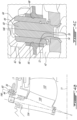
- Figs 4A to 4C presents another embodiment.
- a component referred to as a slide block 60 is introduced and can reduce the effects of wear in some embodiments.
- the slide blocks 60 can be mounted to corresponding pins 44 in a manner to be rotatable around the corresponding pin axes 146.
- the slide block 60 can be designed in a manner have two slide block faces 62, 64, which can face transversally opposite sides relative the pin axis 146, and which are configured to offer a smoother and larger sliding surfaces against the corresponding faces 66, 68 of the of the guide slot 48 than a cylindrical pin would have (see Fig. 4C ).
- the slide block 60 rotates around the pin axis 146, it can accommodate the change of angular orientation between the length of the guide slot 48 and the pin 44 as the actuator ring 42 rotates (the movement perhaps best illustrated by comparing Fig. 2A to Fig. 3A ).
- the two slide block faces 62, 64 can be planar, flat, and parallel to one another.
- the two guide slot faces 66, 68 can also be planar, flat and parallel to one another.
- the slide block 60 can form a broader, rotating intermediary between the pin 44 and the guide slot 48, and which may be designed to maintain surface contact throughout the entire actuator stroke.
- vane axes 134 The general geometry of the vane axes 134, pin axes 146, main axis 11, vane arms 36, guide slots 48, and actuator ring 42 are generally as described above with reference to Figs. 2A to 3C , with some exceptions.
- the vane axis 134 extends obliquely rather than radially relative the main axis.
- the variable vanes 130 are used in a curving portion of the main gas path 122 and to operate efficiently, its angle relative to the main axis 11 is selected accordingly.
- the pin axis 146 around which the slide block 60 is rotatably mounted here, is even further sloping relative the main axis 11. Notwithstanding these angles, the pin axis 146 remains configured to intersect the vane axis 134 roughly around the main axis 11, to facilitate the accommodation of the relative displacements between the vane arm 36 and the pin 44, similarly to how the pin axis 46 and vane axis 34 intersected along the main axis in Fig. 2C and 3C .
- the angles can vary strongly from one embodiment to another.
- the vane axes 134 can have more than 65 degrees relative the main axis 11, and in some embodiments, both the vane axes 134 and the pin axes 146 can have at least 80 degrees relative the main axis 11.
- the movement of the slide block 60 in the guide slot 48 may not be purely along the length of the guide slot 48 when the vane arm 36 pivots, but may be oblique and include a somewhat radially oriented component due to the presence of an increasing spacing s (see Fig. 3B ). Such movement may tend to pull or push the slide block 60 along the pin axis 146 over time.
- a snapping feature may be introduced.
- the pin 44 is generally cylindrical around the pin axis 146 except for a pin slot 70 formed annularly around its outer circumference at a given axial position.
- the slide block 60 has a pin aperture delimited by an internal wall which is generally cylindrical except for a block slot 72 formed annularly around its inner circumference at a given axial position.
- a resilient retaining ring 74 can be engaged with a first one of the block slot 72 and pin slot 70 and elastically deformed in a manner to accommodate the engagement of the pin 44 inside the pin aperture until the block slot 72 becomes axially aligned with the pin slot 70, at which point the elastic energy stored in the elastically deformed resilient retaining ring 74 can be released to snap the retaining ring 74 further into the other one of the pin slot 70 and block slot 72, bridging the two, at which point the retaining ring 74 may retain the slide block 60 axially relative the pin 44 in the orientation of the pin axis 146.
- the retaining ring 74 If the retaining ring 74 is first engaged into the pin slot 70, it can be compressed to accommodate the cylindrical portion of the pin aperture and expand into the block slot 72 upon axial alignment, whereas if the retaining ring is first engaged into the block slot 72, it can be stretched to accommodate the cylindrical portion of the pin 44 and contract upon axial alignment.
- the engaging end of the pin 44, of the pin aperture, or of both the pin 44 and the pin aperture can beveled in a manner to assist or drive the elastic deformation of the resilient retaining ring 74 prior to its release.
- the slide block 60 can be designed for being split into two pieces by an appropriate splitting tool to this end.
- the slide block 60 can be provided with removal grooves 80, 82 to accommodate opposed splitting members of a compressive splitting tool.
- the removal grooves 80, 82 can be defined parallel to the pin axis 146, and can be provided on opposite removal faces of the slide block 60.
- the removal faces can extend between corresponding edges of the slide block faces 62, 64 which are designed for maintaining a surface contact with the corresponding guide slot faces 66, 68.
- the pins 44 are designed in the form of initially separate components which are riveted to the annular body of the actuator ring 42 in this embodiment, as best seen in Fig. 4C .
- Other configurations are possible in alternate embodiments. Once assembled, the pins protrude from the annular body and the pin axes extend away from the main axis.
- the guide slots can be defined along the length of corresponding ones of the vane arms.
- An actuator 84 which can be of any suitable type such as pneumatic, hydraulic or electric, can be used to drive the rotation of the actuator ring 42 around the main axis 11.
- the actuator 84 can have a cylinder which extends a shaft mounted to a piston received in the cylinder.
- a shaft can be pivotally mounted to the actuator ring at the distal end, such as exemplified in Fig. 4A .
- the vane arm can be manufactured integrally with the vane, such as by casting, additive manufacturing or machining, or provided initially as a separate component configured to be assembled to the vane.
- the vane arms have a generally rectangular slide with rounded corners.
- the rounded corners can help reduce stress concentration.
- reinforcing ribs are present on both circumferentially opposite sides of the vane arms which can be useful from a structural point of view in some embodiments.
- the actuator ring can have a plurality of apertures formed therethrough, as shown, in a manner to optimize the structural characteristics while also factoring in minimization of weight and material costs. Many variations are possible in alternate embodiments.
- the method can include rotating 100 the actuator ring around a main axis, the rotation of the actuator ring pivoting the vane arms and thereby rotating the corresponding vanes around the vane axes, via sliding of the slide blocks in the guide slots and rotation of the slide blocks around the guide pins, the sliding of the slide blocks in the guide slots occurring obliquely relative the length of the guide slots.
- the method Prior to rotating the actuator ring, the method includes assembling 102 the slide blocks to corresponding ones of the pins, said assembling including engaging a resilient retaining ring into a pin annular slot defined around each pin, around the pin axis, compressing the resilient retaining ring into the pin annular slot, sliding an inner wall of the corresponding slide block over the compressed resilient ring until a block annular slot defined in the inner wall comes into alignment with the retaining ring, at which point the compressed retaining ring expands into the block annular slot and retains the slide block along the pin axis.
- the method can include removing 104 the slide blocks from corresponding ones of the pins, said removing including splitting the slide block into two halves with a removal tool
- the pins can be incorporated to the vane arms, can extend generally radially outwardly or generally radially inwardly, possibly obliquely relative the main axis, and the guide slots can be formed in the actuator ring in alternate embodiments.
- the guide slots can be formed in the actuator ring in alternate embodiments.
Landscapes
- Engineering & Computer Science (AREA)
- Mechanical Engineering (AREA)
- General Engineering & Computer Science (AREA)
- Control Of Turbines (AREA)
Claims (11)
- Mechanismus (50) einer verstellbaren Leitschaufel, umfassend:ein Gehäuse (32);einen Betätigerring (42), der einen ringförmigen Körper aufweist, der um eine Hauptachse (11) definiert ist, wobei der Betätigerring (42) drehbar an dem Gehäuse (32) zur Drehung um die Hauptachse (11) angebracht ist;einen Satz von Leitschaufeln (28), der eine Vielzahl von Leitschaufeln (30) beinhaltet, die umlaufend um die Hauptachse (11) verteilt sind, wobei jede Leitschaufel (30) des Satzes von Leitschaufeln (28) eine Leitschaufelachse (34) aufweist, die sich von einem inneren Ende (38) zu einem äußeren Ende (40) erstreckt, wobei das innere Ende (38) und das äußere Ende (40) drehbar am Gehäuse (32) angebracht sind, um eine Drehung der entsprechenden Leitschaufel (30) um die Leitschaufelachse (34) zu ermöglichen, wobei sich die Leitschaufelachsen (34) nicht parallel zur Hauptachse (11) erstrecken, wobei jede Leitschaufel (30) einen Leitschaufelarm (36) mit einer Leitschaufelarmlänge aufweist, die sich quer zur Leitschaufelachse (34) erstreckt;einen ersten von dem Betätigungsring (42) und den Leitschaufelarmen (36), der eine Vielzahl von Stiften (44) aufweist, die umlaufend um die Hauptachse (11) verteilt sind, wobei sich jeder Stift (44) entlang einer Stiftachse (46) erstreckt;eine Vielzahl von Gleitblöcken (60), wobei jeder Gleitblock (60) drehbar an einem entsprechenden der Stifte (44) zur Drehung um die Stiftachse (46) angebracht ist, wobei jeder Gleitblock (60) zwei Gleitblockflächen (62, 64) aufweist, die in Relation zu der Stiftachse (46) quer gegenüberliegenden Seiten zugewandt sind; undeinen zweiten von dem Betätigungsring (42) und den Schaufelarmen (36), der eine Vielzahl von Leitschaufeln (48) aufweist, wobei jede Leitschaufel (48) eine Länge aufweist, die sich von einer entsprechenden Schaufelachse (34) weg erstreckt, wobei jede Leitschaufel (48) verschiebbar einen entsprechenden der Gleitblöcke (60) aufnimmt, wobei jede der beiden Gleitblockflächen (62, 64) verschiebbar von einer entsprechenden Leitschaufelfläche (66, 68) der entsprechenden Leitschaufel (48) aufgenommen wird,dadurch gekennzeichnet, dass:
die Stiftachsen (46) die Achsen der Leitschaufeln (34) entlang der Hauptachse (11) kreuzen. - Mechanismus einer verstellbaren Leitschaufel nach Anspruch 1, wobei die Leitschaufeln (60) auf den entsprechenden Stiften (44) entlang einer Ausrichtung der Stiftachse (46) durch einen elastischen Haltering (74) gehalten werden, wobei sich der Haltering (74) teilweise in einen Schlitz (70) erstreckt, der um den Stift (44) herum definiert ist, und teilweise in einen Schlitz (72), der um eine zentrale Öffnung der Leitschaufeln (60) herum definiert ist.
- Mechanismus (50) einer verstellbaren Leitschaufel nach Anspruch 1 oder 2, wobei die Stifte (44) an den Betätigungsring (42) genietet sind.
- Mechanismus (50) einer verstellbaren Leitschaufel nach einem der vorhergehenden Ansprüche, wobei die Leitschaufeln (60) jeweils zwei Entfernungsnuten (80, 82) aufweisen, die sich parallel zu dem Stift (44) auf gegenüberliegenden Entfernungsflächen erstrecken, wobei sich die Entfernungsflächen zwischen entsprechenden Kanten der Leitschaufelflächen (62, 64) erstrecken.
- Mechanismus (50) einer verstellbaren Leitschaufel nach einem der vorhergehenden Ansprüche, wobei die Stifte (44) aus dem ringförmigen Körper herausragen und die Stiftachsen (46) sich von der Hauptachse (11) weg erstrecken, wobei die Leitschaufelsteckplätze (48) entlang der Länge der entsprechenden Leitschaufelarme (36) definiert sind.
- Mechanismus (50) einer verstellbaren Leitschaufel nach einem der vorhergehenden Ansprüche, wobei ein Winkel zwischen der Hauptachse (11) und den Leitschaufelachsen (34) mindestens 65 Grad beträgt.
- Mechanismus (50) einer verstellbaren Leitschaufel nach Anspruch 6, wobei ein Winkel zwischen der Hauptachse (11) und der Leitschaufel- und der Stiftachse (34, 46) mindestens 80 Grad beträgt.
- Mechanismus (50) einer verstellbaren Leitschaufel nach einem der vorhergehenden Ansprüche, wobei die beiden Gleitblockflächen (62, 64) eines jeden Gleitblocks (60) und die beiden Leitschaufelschlitzflächen (66, 68) eines jeden Leitschaufelschlitzes (48) eben, flach und parallel sind.
- Gasturbinentriebwerk (10), umfassend den Mechanismus (50) einer verstellbaren Leitschaufel nach einem der vorhergehenden Ansprüche, wobei:das Gehäuse (32) einen Gasweg (22) definiert, der sich nacheinander über einen Kompressorabschnitt (14), eine Brennkammer (16) und einen Turbinenabschnitt (18) erstreckt, wobei sich der Gasweg (22) ringförmig um eine Hauptachse (11) erstreckt, wobei mindestens ein Rotor drehbar an dem Gehäuse (32) zur Drehung um die Hauptachse (11) angebracht ist, wobei der Rotor einen Satz von Blättern (24) aufweist, die einen Teil des Kompressorabschnitts (14) bilden; undder Satz von Leitschaufeln (28) dem Satz von Blättern (24) entlang des Gasweges (22) benachbart ist.
- Verfahren zum Betrieb eines Mechanismus (50) einer verstellbaren Leitschaufel, aufweisendeinen Betätigerring (42), der um eine Hauptachse (11) definiert ist;einen Satz von Leitschaufeln (28), der eine Vielzahl von Leitschaufeln (30) aufweist, die umlaufend um die Hauptachse (11) verteilt sind, wobei jede Leitschaufel (30) Folgendes aufweist:eine Leitschaufelachse (34), die sich von einem inneren Ende (38) zu einem äußeren Ende (40) erstreckt und um die Leitschaufelachse (34) drehbar ist; undeinen Leitschaufelarm (36);eine Vielzahl von Stiften (44), die umlaufend um die Hauptachse (11) verteilt sind, wobei sich jeder Stift (44) entlang einer Stiftachse (46) erstreckt;Gleitblöcke (60), die mit entsprechenden der Stifte (44) so in Eingriff stehen, dass sie sich um die Stifte (44) drehen; undFührungsschlitze (48), die eine Länge aufweisen, die sich von entsprechenden der Leitschaufelachsen (34) weg erstreckt, wobei jeder Führungsschlitz (48) einen entsprechenden Gleitblock (60) gleitend aufnimmt,wobei das Verfahren Folgendes umfasst:Drehen des Betätigungsrings (42) um die Hauptachse (11), wobei die Drehung des Betätigungsrings (42) die Leitschaufelarme (36) schwenkt und dadurch die entsprechenden Leitschaufeln (30) um die Leitschaufelachsen (34) dreht, durch Gleiten der Gleitblöcke (60) in den Führungsschlitzen (48) und Drehen der Gleitblöcke (60) um die Stifte (44), wobei das Gleiten der Gleitblöcke (60) in den Führungsschlitzen (48) schräg in Relation zur Länge der Führungsschlitze (48) erfolgt,dadurch gekennzeichnet, dass das Verfahren vor der Drehung des Betätigerrings (42) ferner Folgendes umfasst:Zusammenfügen der Gleitblöcke (60) mit entsprechenden der Stifte (44), wobei das Zusammenfügen das Eingreifen eines elastischen Halterings (74) in einen ersten ringförmigen Schlitz (70, 72), der um die Stiftachse (46) herum definiert ist, in einem ersten der Stifte (44) und in eine Innenwand, die eine Öffnung für den Stift im Gleitblock (60) begrenzt, beinhaltet; undEingreifen des Stifts (44) in die Stiftöffnung des Gleitblocks (60), das das Aufrechterhalten des elastischen Halterings (74) in einem elastisch verformten Zustand beinhaltet, bis der erste ringförmige Schlitz (70, 72) axial mit einem zweiten ringförmigen Schlitz (70, 72) ausgerichtet wird, der in dem zweiten von Stift (44) und Innenwand gebildet ist, wobei eine elastische Verformungsenergie des elastischen Halterings (74) den elastischen Haltering (74) ferner mit dem zweiten ringförmigen Schlitz (70, 72) in einer Weise in Eingriff bringt, dass der Gleitblock (60) danach entlang der Stiftachse (46) gehalten wird.
- Verfahren nach Anspruch 10, ferner umfassend, nach dem Drehen des Betätigerrings (42), Entfernen der Gleitblöcke (60) von entsprechenden der Stifte (44), wobei das Entfernen das Spalten des Gleitblocks (60) in zwei Hälften mit einem Entfernungswerkzeug beinhaltet.
Applications Claiming Priority (1)
| Application Number | Priority Date | Filing Date | Title |
|---|---|---|---|
| US17/471,733 US11708767B2 (en) | 2021-09-10 | 2021-09-10 | Variable vane arm mechanism for gas turbine engine and method of operation |
Publications (2)
| Publication Number | Publication Date |
|---|---|
| EP4148237A1 EP4148237A1 (de) | 2023-03-15 |
| EP4148237B1 true EP4148237B1 (de) | 2024-11-06 |
Family
ID=83283237
Family Applications (1)
| Application Number | Title | Priority Date | Filing Date |
|---|---|---|---|
| EP22195227.8A Active EP4148237B1 (de) | 2021-09-10 | 2022-09-12 | Mechanismus einer verstellbaren leitsschaufel, gastturbinentriebwerk und verfahren zum betrieb eines mechanismus einer verstellbaren leitsschaufel |
Country Status (3)
| Country | Link |
|---|---|
| US (1) | US11708767B2 (de) |
| EP (1) | EP4148237B1 (de) |
| CA (1) | CA3170499A1 (de) |
Families Citing this family (4)
| Publication number | Priority date | Publication date | Assignee | Title |
|---|---|---|---|---|
| US11982193B1 (en) * | 2022-12-30 | 2024-05-14 | Rolls-Royce North American Technologies Inc. | Systems and methods for multi-dimensional variable vane stage rigging utilizing adjustable inclined mechanisms |
| CN119491843B (zh) * | 2023-08-16 | 2025-11-25 | 中国航发商用航空发动机有限责任公司 | 一种静子叶片调节机构及压气机 |
| CN117345353B (zh) * | 2023-12-04 | 2024-01-26 | 西北工业大学 | 一种具有变长度摇臂的可调静子结构及压气机 |
| CN117874929B (zh) * | 2024-03-12 | 2024-06-04 | 中国航发四川燃气涡轮研究院 | 一种具有流动稳定性的涡流器叶片型面设计方法 |
Family Cites Families (10)
| Publication number | Priority date | Publication date | Assignee | Title |
|---|---|---|---|---|
| US2778564A (en) | 1953-12-01 | 1957-01-22 | Havilland Engine Co Ltd | Stator blade ring assemblies for axial flow compressors and the like |
| US3356288A (en) * | 1965-04-07 | 1967-12-05 | Gen Electric | Stator adjusting means for axial flow compressors or the like |
| US3954349A (en) * | 1975-06-02 | 1976-05-04 | United Technologies Corporation | Lever connection to syncring |
| US3990809A (en) * | 1975-07-24 | 1976-11-09 | United Technologies Corporation | High ratio actuation linkage |
| US6527508B2 (en) * | 2001-08-03 | 2003-03-04 | Mark Groskreutz | Actuator crank arm design for variable nozzle turbocharger |
| DE102004057864A1 (de) | 2004-11-30 | 2006-06-01 | Borgwarner Inc.(N.D.Ges.D.Staates Delaware), Auburn Hills | Abgasturbolader, Leitapparat für einen Abgasturbolader sowie Schaufelhebel für einen Leitapparat |
| EP1669548A1 (de) * | 2004-12-08 | 2006-06-14 | ABB Turbo Systems AG | Leitapparat für Abgasturbine |
| DE112014004824T5 (de) | 2013-11-26 | 2016-07-21 | Borgwarner Inc. | VTG-Turbolader mit durch ein gemeinsam genutztes Stellglied geregeltem Wastegate |
| US9638212B2 (en) * | 2013-12-19 | 2017-05-02 | Pratt & Whitney Canada Corp. | Compressor variable vane assembly |
| US9874106B2 (en) * | 2015-10-21 | 2018-01-23 | Borgwarner Inc. | VTG lever positive displacement press joint |
-
2021
- 2021-09-10 US US17/471,733 patent/US11708767B2/en active Active
-
2022
- 2022-08-15 CA CA3170499A patent/CA3170499A1/en active Pending
- 2022-09-12 EP EP22195227.8A patent/EP4148237B1/de active Active
Also Published As
| Publication number | Publication date |
|---|---|
| EP4148237A1 (de) | 2023-03-15 |
| US11708767B2 (en) | 2023-07-25 |
| US20230078588A1 (en) | 2023-03-16 |
| CA3170499A1 (en) | 2023-03-10 |
Similar Documents
| Publication | Publication Date | Title |
|---|---|---|
| EP4148237B1 (de) | Mechanismus einer verstellbaren leitsschaufel, gastturbinentriebwerk und verfahren zum betrieb eines mechanismus einer verstellbaren leitsschaufel | |
| US5228828A (en) | Gas turbine engine clearance control apparatus | |
| US20070020091A1 (en) | Synch ring variable vane synchronizing mechanism for inner diameter vane shroud | |
| EP2961934B1 (de) | Gasturbinenkomponente mit variabler geometrie | |
| US10626747B2 (en) | Variable vane actuation arrangement | |
| EP1586744A2 (de) | Verstellbare Leitschaufelanordnung einer Gasturbine | |
| US10539024B2 (en) | Variable pitch fan for a gas turbine engine | |
| EP4023858B1 (de) | Verstellbare leitschaufel, gasturbinentriebwerk und verfahren zum betreiben einer verstellbaren leitschaufel | |
| US10443412B2 (en) | Variable pitch fan pitch range limiter | |
| US9752450B2 (en) | Turbine engine tip clearance control system with later translatable slide block | |
| US11002141B2 (en) | Method and system for leading edge auxiliary turbine vanes | |
| CN114526264B (zh) | 具有衬套环和偏置构件的可变导向叶片组件 | |
| US20220162959A1 (en) | Unison member for variable guide vane | |
| CN101782000A (zh) | 涡轮叶片根部构造 | |
| EP2895704B1 (de) | Synchronring eines gasturbinenmotors mit mehrachsigem gelenk | |
| US11851158B2 (en) | Variable pitch fan assembly with remote counterweights | |
| RU2644001C2 (ru) | Вентилятор с изменяемым углом установки путем различного вращения дисков вентилятора | |
| EP4317657A1 (de) | Variable leitschaufelanordnung für gasturbinenmotor | |
| EP4043698A1 (de) | Verstellbare leitschaufelanordnung für ein gasturbinentriebwerk und gasturbinentriebwerk | |
| JP5325004B2 (ja) | 静翼翼角可変装置および軸流式圧縮機 |
Legal Events
| Date | Code | Title | Description |
|---|---|---|---|
| PUAI | Public reference made under article 153(3) epc to a published international application that has entered the european phase |
Free format text: ORIGINAL CODE: 0009012 |
|
| STAA | Information on the status of an ep patent application or granted ep patent |
Free format text: STATUS: THE APPLICATION HAS BEEN PUBLISHED |
|
| AK | Designated contracting states |
Kind code of ref document: A1 Designated state(s): AL AT BE BG CH CY CZ DE DK EE ES FI FR GB GR HR HU IE IS IT LI LT LU LV MC MK MT NL NO PL PT RO RS SE SI SK SM TR |
|
| STAA | Information on the status of an ep patent application or granted ep patent |
Free format text: STATUS: REQUEST FOR EXAMINATION WAS MADE |
|
| 17P | Request for examination filed |
Effective date: 20230914 |
|
| RBV | Designated contracting states (corrected) |
Designated state(s): AL AT BE BG CH CY CZ DE DK EE ES FI FR GB GR HR HU IE IS IT LI LT LU LV MC MK MT NL NO PL PT RO RS SE SI SK SM TR |
|
| GRAP | Despatch of communication of intention to grant a patent |
Free format text: ORIGINAL CODE: EPIDOSNIGR1 |
|
| STAA | Information on the status of an ep patent application or granted ep patent |
Free format text: STATUS: GRANT OF PATENT IS INTENDED |
|
| RIC1 | Information provided on ipc code assigned before grant |
Ipc: F04D 29/56 20060101ALN20231128BHEP Ipc: F01D 17/16 20060101AFI20231128BHEP |
|
| INTG | Intention to grant announced |
Effective date: 20231219 |
|
| GRAJ | Information related to disapproval of communication of intention to grant by the applicant or resumption of examination proceedings by the epo deleted |
Free format text: ORIGINAL CODE: EPIDOSDIGR1 |
|
| STAA | Information on the status of an ep patent application or granted ep patent |
Free format text: STATUS: REQUEST FOR EXAMINATION WAS MADE |
|
| GRAP | Despatch of communication of intention to grant a patent |
Free format text: ORIGINAL CODE: EPIDOSNIGR1 |
|
| STAA | Information on the status of an ep patent application or granted ep patent |
Free format text: STATUS: GRANT OF PATENT IS INTENDED |
|
| INTC | Intention to grant announced (deleted) | ||
| RIC1 | Information provided on ipc code assigned before grant |
Ipc: F04D 29/56 20060101ALN20240423BHEP Ipc: F01D 17/16 20060101AFI20240423BHEP |
|
| INTG | Intention to grant announced |
Effective date: 20240528 |
|
| GRAS | Grant fee paid |
Free format text: ORIGINAL CODE: EPIDOSNIGR3 |
|
| GRAA | (expected) grant |
Free format text: ORIGINAL CODE: 0009210 |
|
| STAA | Information on the status of an ep patent application or granted ep patent |
Free format text: STATUS: THE PATENT HAS BEEN GRANTED |
|
| AK | Designated contracting states |
Kind code of ref document: B1 Designated state(s): AL AT BE BG CH CY CZ DE DK EE ES FI FR GB GR HR HU IE IS IT LI LT LU LV MC MK MT NL NO PL PT RO RS SE SI SK SM TR |
|
| REG | Reference to a national code |
Ref country code: GB Ref legal event code: FG4D |
|
| REG | Reference to a national code |
Ref country code: CH Ref legal event code: EP |
|
| REG | Reference to a national code |
Ref country code: DE Ref legal event code: R096 Ref document number: 602022007427 Country of ref document: DE |
|
| REG | Reference to a national code |
Ref country code: IE Ref legal event code: FG4D |
|
| REG | Reference to a national code |
Ref country code: LT Ref legal event code: MG9D |
|
| REG | Reference to a national code |
Ref country code: NL Ref legal event code: MP Effective date: 20241106 |
|
| PG25 | Lapsed in a contracting state [announced via postgrant information from national office to epo] |
Ref country code: IS Free format text: LAPSE BECAUSE OF FAILURE TO SUBMIT A TRANSLATION OF THE DESCRIPTION OR TO PAY THE FEE WITHIN THE PRESCRIBED TIME-LIMIT Effective date: 20250306 Ref country code: HR Free format text: LAPSE BECAUSE OF FAILURE TO SUBMIT A TRANSLATION OF THE DESCRIPTION OR TO PAY THE FEE WITHIN THE PRESCRIBED TIME-LIMIT Effective date: 20241106 Ref country code: PT Free format text: LAPSE BECAUSE OF FAILURE TO SUBMIT A TRANSLATION OF THE DESCRIPTION OR TO PAY THE FEE WITHIN THE PRESCRIBED TIME-LIMIT Effective date: 20250306 |
|
| PG25 | Lapsed in a contracting state [announced via postgrant information from national office to epo] |
Ref country code: FI Free format text: LAPSE BECAUSE OF FAILURE TO SUBMIT A TRANSLATION OF THE DESCRIPTION OR TO PAY THE FEE WITHIN THE PRESCRIBED TIME-LIMIT Effective date: 20241106 Ref country code: NL Free format text: LAPSE BECAUSE OF FAILURE TO SUBMIT A TRANSLATION OF THE DESCRIPTION OR TO PAY THE FEE WITHIN THE PRESCRIBED TIME-LIMIT Effective date: 20241106 |
|
| REG | Reference to a national code |
Ref country code: AT Ref legal event code: MK05 Ref document number: 1739557 Country of ref document: AT Kind code of ref document: T Effective date: 20241106 |
|
| PG25 | Lapsed in a contracting state [announced via postgrant information from national office to epo] |
Ref country code: BG Free format text: LAPSE BECAUSE OF FAILURE TO SUBMIT A TRANSLATION OF THE DESCRIPTION OR TO PAY THE FEE WITHIN THE PRESCRIBED TIME-LIMIT Effective date: 20241106 |
|
| PG25 | Lapsed in a contracting state [announced via postgrant information from national office to epo] |
Ref country code: ES Free format text: LAPSE BECAUSE OF FAILURE TO SUBMIT A TRANSLATION OF THE DESCRIPTION OR TO PAY THE FEE WITHIN THE PRESCRIBED TIME-LIMIT Effective date: 20241106 |
|
| PG25 | Lapsed in a contracting state [announced via postgrant information from national office to epo] |
Ref country code: NO Free format text: LAPSE BECAUSE OF FAILURE TO SUBMIT A TRANSLATION OF THE DESCRIPTION OR TO PAY THE FEE WITHIN THE PRESCRIBED TIME-LIMIT Effective date: 20250206 |
|
| PG25 | Lapsed in a contracting state [announced via postgrant information from national office to epo] |
Ref country code: LV Free format text: LAPSE BECAUSE OF FAILURE TO SUBMIT A TRANSLATION OF THE DESCRIPTION OR TO PAY THE FEE WITHIN THE PRESCRIBED TIME-LIMIT Effective date: 20241106 Ref country code: GR Free format text: LAPSE BECAUSE OF FAILURE TO SUBMIT A TRANSLATION OF THE DESCRIPTION OR TO PAY THE FEE WITHIN THE PRESCRIBED TIME-LIMIT Effective date: 20250207 Ref country code: AT Free format text: LAPSE BECAUSE OF FAILURE TO SUBMIT A TRANSLATION OF THE DESCRIPTION OR TO PAY THE FEE WITHIN THE PRESCRIBED TIME-LIMIT Effective date: 20241106 |
|
| PG25 | Lapsed in a contracting state [announced via postgrant information from national office to epo] |
Ref country code: PL Free format text: LAPSE BECAUSE OF FAILURE TO SUBMIT A TRANSLATION OF THE DESCRIPTION OR TO PAY THE FEE WITHIN THE PRESCRIBED TIME-LIMIT Effective date: 20241106 |
|
| PG25 | Lapsed in a contracting state [announced via postgrant information from national office to epo] |
Ref country code: RS Free format text: LAPSE BECAUSE OF FAILURE TO SUBMIT A TRANSLATION OF THE DESCRIPTION OR TO PAY THE FEE WITHIN THE PRESCRIBED TIME-LIMIT Effective date: 20250206 |
|
| PG25 | Lapsed in a contracting state [announced via postgrant information from national office to epo] |
Ref country code: SM Free format text: LAPSE BECAUSE OF FAILURE TO SUBMIT A TRANSLATION OF THE DESCRIPTION OR TO PAY THE FEE WITHIN THE PRESCRIBED TIME-LIMIT Effective date: 20241106 |
|
| PG25 | Lapsed in a contracting state [announced via postgrant information from national office to epo] |
Ref country code: DK Free format text: LAPSE BECAUSE OF FAILURE TO SUBMIT A TRANSLATION OF THE DESCRIPTION OR TO PAY THE FEE WITHIN THE PRESCRIBED TIME-LIMIT Effective date: 20241106 |
|
| PG25 | Lapsed in a contracting state [announced via postgrant information from national office to epo] |
Ref country code: EE Free format text: LAPSE BECAUSE OF FAILURE TO SUBMIT A TRANSLATION OF THE DESCRIPTION OR TO PAY THE FEE WITHIN THE PRESCRIBED TIME-LIMIT Effective date: 20241106 |
|
| PG25 | Lapsed in a contracting state [announced via postgrant information from national office to epo] |
Ref country code: RO Free format text: LAPSE BECAUSE OF FAILURE TO SUBMIT A TRANSLATION OF THE DESCRIPTION OR TO PAY THE FEE WITHIN THE PRESCRIBED TIME-LIMIT Effective date: 20241106 |
|
| PG25 | Lapsed in a contracting state [announced via postgrant information from national office to epo] |
Ref country code: SK Free format text: LAPSE BECAUSE OF FAILURE TO SUBMIT A TRANSLATION OF THE DESCRIPTION OR TO PAY THE FEE WITHIN THE PRESCRIBED TIME-LIMIT Effective date: 20241106 |
|
| PG25 | Lapsed in a contracting state [announced via postgrant information from national office to epo] |
Ref country code: CZ Free format text: LAPSE BECAUSE OF FAILURE TO SUBMIT A TRANSLATION OF THE DESCRIPTION OR TO PAY THE FEE WITHIN THE PRESCRIBED TIME-LIMIT Effective date: 20241106 |
|
| PG25 | Lapsed in a contracting state [announced via postgrant information from national office to epo] |
Ref country code: IT Free format text: LAPSE BECAUSE OF FAILURE TO SUBMIT A TRANSLATION OF THE DESCRIPTION OR TO PAY THE FEE WITHIN THE PRESCRIBED TIME-LIMIT Effective date: 20241106 |
|
| REG | Reference to a national code |
Ref country code: DE Ref legal event code: R097 Ref document number: 602022007427 Country of ref document: DE |
|
| PG25 | Lapsed in a contracting state [announced via postgrant information from national office to epo] |
Ref country code: SE Free format text: LAPSE BECAUSE OF FAILURE TO SUBMIT A TRANSLATION OF THE DESCRIPTION OR TO PAY THE FEE WITHIN THE PRESCRIBED TIME-LIMIT Effective date: 20241106 |
|
| PLBE | No opposition filed within time limit |
Free format text: ORIGINAL CODE: 0009261 |
|
| STAA | Information on the status of an ep patent application or granted ep patent |
Free format text: STATUS: NO OPPOSITION FILED WITHIN TIME LIMIT |
|
| PGFP | Annual fee paid to national office [announced via postgrant information from national office to epo] |
Ref country code: DE Payment date: 20250820 Year of fee payment: 4 |
|
| 26N | No opposition filed |
Effective date: 20250807 |
|
| PGFP | Annual fee paid to national office [announced via postgrant information from national office to epo] |
Ref country code: FR Payment date: 20250820 Year of fee payment: 4 |