EP4148276A1 - Compresseur - Google Patents
Compresseur Download PDFInfo
- Publication number
- EP4148276A1 EP4148276A1 EP21833778.0A EP21833778A EP4148276A1 EP 4148276 A1 EP4148276 A1 EP 4148276A1 EP 21833778 A EP21833778 A EP 21833778A EP 4148276 A1 EP4148276 A1 EP 4148276A1
- Authority
- EP
- European Patent Office
- Prior art keywords
- stator
- peripheral surface
- compressor
- narrow portion
- casing
- Prior art date
- Legal status (The legal status is an assumption and is not a legal conclusion. Google has not performed a legal analysis and makes no representation as to the accuracy of the status listed.)
- Granted
Links
Images



Classifications
-
- F—MECHANICAL ENGINEERING; LIGHTING; HEATING; WEAPONS; BLASTING
- F04—POSITIVE - DISPLACEMENT MACHINES FOR LIQUIDS; PUMPS FOR LIQUIDS OR ELASTIC FLUIDS
- F04B—POSITIVE-DISPLACEMENT MACHINES FOR LIQUIDS; PUMPS
- F04B53/00—Component parts, details or accessories not provided for in, or of interest apart from, groups F04B1/00 - F04B23/00 or F04B39/00 - F04B47/00
- F04B53/08—Cooling; Heating; Preventing freezing
-
- F—MECHANICAL ENGINEERING; LIGHTING; HEATING; WEAPONS; BLASTING
- F04—POSITIVE - DISPLACEMENT MACHINES FOR LIQUIDS; PUMPS FOR LIQUIDS OR ELASTIC FLUIDS
- F04B—POSITIVE-DISPLACEMENT MACHINES FOR LIQUIDS; PUMPS
- F04B35/00—Piston pumps specially adapted for elastic fluids and characterised by the driving means to their working members, or by combination with, or adaptation to, specific driving engines or motors, not otherwise provided for
- F04B35/04—Piston pumps specially adapted for elastic fluids and characterised by the driving means to their working members, or by combination with, or adaptation to, specific driving engines or motors, not otherwise provided for the means being electric
-
- F—MECHANICAL ENGINEERING; LIGHTING; HEATING; WEAPONS; BLASTING
- F04—POSITIVE - DISPLACEMENT MACHINES FOR LIQUIDS; PUMPS FOR LIQUIDS OR ELASTIC FLUIDS
- F04B—POSITIVE-DISPLACEMENT MACHINES FOR LIQUIDS; PUMPS
- F04B39/00—Component parts, details, or accessories, of pumps or pumping systems specially adapted for elastic fluids, not otherwise provided for in, or of interest apart from, groups F04B25/00 - F04B37/00
- F04B39/02—Lubrication
-
- F—MECHANICAL ENGINEERING; LIGHTING; HEATING; WEAPONS; BLASTING
- F04—POSITIVE - DISPLACEMENT MACHINES FOR LIQUIDS; PUMPS FOR LIQUIDS OR ELASTIC FLUIDS
- F04B—POSITIVE-DISPLACEMENT MACHINES FOR LIQUIDS; PUMPS
- F04B39/00—Component parts, details, or accessories, of pumps or pumping systems specially adapted for elastic fluids, not otherwise provided for in, or of interest apart from, groups F04B25/00 - F04B37/00
- F04B39/02—Lubrication
- F04B39/0223—Lubrication characterised by the compressor type
- F04B39/023—Hermetic compressors
- F04B39/0238—Hermetic compressors with oil distribution channels
-
- F—MECHANICAL ENGINEERING; LIGHTING; HEATING; WEAPONS; BLASTING
- F04—POSITIVE - DISPLACEMENT MACHINES FOR LIQUIDS; PUMPS FOR LIQUIDS OR ELASTIC FLUIDS
- F04B—POSITIVE-DISPLACEMENT MACHINES FOR LIQUIDS; PUMPS
- F04B39/00—Component parts, details, or accessories, of pumps or pumping systems specially adapted for elastic fluids, not otherwise provided for in, or of interest apart from, groups F04B25/00 - F04B37/00
- F04B39/02—Lubrication
- F04B39/0223—Lubrication characterised by the compressor type
- F04B39/023—Hermetic compressors
- F04B39/0238—Hermetic compressors with oil distribution channels
- F04B39/0246—Hermetic compressors with oil distribution channels in the rotating shaft
-
- F—MECHANICAL ENGINEERING; LIGHTING; HEATING; WEAPONS; BLASTING
- F04—POSITIVE - DISPLACEMENT MACHINES FOR LIQUIDS; PUMPS FOR LIQUIDS OR ELASTIC FLUIDS
- F04B—POSITIVE-DISPLACEMENT MACHINES FOR LIQUIDS; PUMPS
- F04B39/00—Component parts, details, or accessories, of pumps or pumping systems specially adapted for elastic fluids, not otherwise provided for in, or of interest apart from, groups F04B25/00 - F04B37/00
- F04B39/02—Lubrication
- F04B39/0223—Lubrication characterised by the compressor type
- F04B39/023—Hermetic compressors
- F04B39/0238—Hermetic compressors with oil distribution channels
- F04B39/0246—Hermetic compressors with oil distribution channels in the rotating shaft
- F04B39/0253—Hermetic compressors with oil distribution channels in the rotating shaft using centrifugal force for transporting the oil
-
- F—MECHANICAL ENGINEERING; LIGHTING; HEATING; WEAPONS; BLASTING
- F04—POSITIVE - DISPLACEMENT MACHINES FOR LIQUIDS; PUMPS FOR LIQUIDS OR ELASTIC FLUIDS
- F04C—ROTARY-PISTON, OR OSCILLATING-PISTON, POSITIVE-DISPLACEMENT MACHINES FOR LIQUIDS; ROTARY-PISTON, OR OSCILLATING-PISTON, POSITIVE-DISPLACEMENT PUMPS
- F04C23/00—Combinations of two or more pumps, each being of rotary-piston or oscillating-piston type, specially adapted for elastic fluids; Pumping installations specially adapted for elastic fluids; Multi-stage pumps specially adapted for elastic fluids
- F04C23/008—Hermetic pumps
-
- F—MECHANICAL ENGINEERING; LIGHTING; HEATING; WEAPONS; BLASTING
- F04—POSITIVE - DISPLACEMENT MACHINES FOR LIQUIDS; PUMPS FOR LIQUIDS OR ELASTIC FLUIDS
- F04C—ROTARY-PISTON, OR OSCILLATING-PISTON, POSITIVE-DISPLACEMENT MACHINES FOR LIQUIDS; ROTARY-PISTON, OR OSCILLATING-PISTON, POSITIVE-DISPLACEMENT PUMPS
- F04C29/00—Component parts, details or accessories of pumps or pumping installations, not provided for in groups F04C18/00 - F04C28/00
- F04C29/0042—Driving elements, brakes, couplings, transmissions specially adapted for pumps
- F04C29/0085—Prime movers
-
- F—MECHANICAL ENGINEERING; LIGHTING; HEATING; WEAPONS; BLASTING
- F04—POSITIVE - DISPLACEMENT MACHINES FOR LIQUIDS; PUMPS FOR LIQUIDS OR ELASTIC FLUIDS
- F04C—ROTARY-PISTON, OR OSCILLATING-PISTON, POSITIVE-DISPLACEMENT MACHINES FOR LIQUIDS; ROTARY-PISTON, OR OSCILLATING-PISTON, POSITIVE-DISPLACEMENT PUMPS
- F04C29/00—Component parts, details or accessories of pumps or pumping installations, not provided for in groups F04C18/00 - F04C28/00
- F04C29/02—Lubrication; Lubricant separation
- F04C29/026—Lubricant separation
-
- F—MECHANICAL ENGINEERING; LIGHTING; HEATING; WEAPONS; BLASTING
- F04—POSITIVE - DISPLACEMENT MACHINES FOR LIQUIDS; PUMPS FOR LIQUIDS OR ELASTIC FLUIDS
- F04C—ROTARY-PISTON, OR OSCILLATING-PISTON, POSITIVE-DISPLACEMENT MACHINES FOR LIQUIDS; ROTARY-PISTON, OR OSCILLATING-PISTON, POSITIVE-DISPLACEMENT PUMPS
- F04C29/00—Component parts, details or accessories of pumps or pumping installations, not provided for in groups F04C18/00 - F04C28/00
- F04C29/04—Heating; Cooling; Heat insulation
- F04C29/045—Heating; Cooling; Heat insulation of the electric motor in hermetic pumps
-
- F—MECHANICAL ENGINEERING; LIGHTING; HEATING; WEAPONS; BLASTING
- F04—POSITIVE - DISPLACEMENT MACHINES FOR LIQUIDS; PUMPS FOR LIQUIDS OR ELASTIC FLUIDS
- F04C—ROTARY-PISTON, OR OSCILLATING-PISTON, POSITIVE-DISPLACEMENT MACHINES FOR LIQUIDS; ROTARY-PISTON, OR OSCILLATING-PISTON, POSITIVE-DISPLACEMENT PUMPS
- F04C18/00—Rotary-piston pumps specially adapted for elastic fluids
- F04C18/30—Rotary-piston pumps specially adapted for elastic fluids having the characteristics covered by two or more of groups F04C18/02, F04C18/08, F04C18/22, F04C18/24, F04C18/48, or having the characteristics covered by one of these groups together with some other type of movement between co-operating members
- F04C18/32—Rotary-piston pumps specially adapted for elastic fluids having the characteristics covered by two or more of groups F04C18/02, F04C18/08, F04C18/22, F04C18/24, F04C18/48, or having the characteristics covered by one of these groups together with some other type of movement between co-operating members having both the movement defined in group F04C18/02 and relative reciprocation between the co-operating members
- F04C18/322—Rotary-piston pumps specially adapted for elastic fluids having the characteristics covered by two or more of groups F04C18/02, F04C18/08, F04C18/22, F04C18/24, F04C18/48, or having the characteristics covered by one of these groups together with some other type of movement between co-operating members having both the movement defined in group F04C18/02 and relative reciprocation between the co-operating members with vanes hinged to the outer member and reciprocating with respect to the outer member
-
- F—MECHANICAL ENGINEERING; LIGHTING; HEATING; WEAPONS; BLASTING
- F04—POSITIVE - DISPLACEMENT MACHINES FOR LIQUIDS; PUMPS FOR LIQUIDS OR ELASTIC FLUIDS
- F04C—ROTARY-PISTON, OR OSCILLATING-PISTON, POSITIVE-DISPLACEMENT MACHINES FOR LIQUIDS; ROTARY-PISTON, OR OSCILLATING-PISTON, POSITIVE-DISPLACEMENT PUMPS
- F04C2240/00—Components
- F04C2240/40—Electric motor
-
- F—MECHANICAL ENGINEERING; LIGHTING; HEATING; WEAPONS; BLASTING
- F04—POSITIVE - DISPLACEMENT MACHINES FOR LIQUIDS; PUMPS FOR LIQUIDS OR ELASTIC FLUIDS
- F04C—ROTARY-PISTON, OR OSCILLATING-PISTON, POSITIVE-DISPLACEMENT MACHINES FOR LIQUIDS; ROTARY-PISTON, OR OSCILLATING-PISTON, POSITIVE-DISPLACEMENT PUMPS
- F04C23/00—Combinations of two or more pumps, each being of rotary-piston or oscillating-piston type, specially adapted for elastic fluids; Pumping installations specially adapted for elastic fluids; Multi-stage pumps specially adapted for elastic fluids
- F04C23/001—Combinations of two or more pumps, each being of rotary-piston or oscillating-piston type, specially adapted for elastic fluids; Pumping installations specially adapted for elastic fluids; Multi-stage pumps specially adapted for elastic fluids of similar working principle
-
- F—MECHANICAL ENGINEERING; LIGHTING; HEATING; WEAPONS; BLASTING
- F04—POSITIVE - DISPLACEMENT MACHINES FOR LIQUIDS; PUMPS FOR LIQUIDS OR ELASTIC FLUIDS
- F04C—ROTARY-PISTON, OR OSCILLATING-PISTON, POSITIVE-DISPLACEMENT MACHINES FOR LIQUIDS; ROTARY-PISTON, OR OSCILLATING-PISTON, POSITIVE-DISPLACEMENT PUMPS
- F04C29/00—Component parts, details or accessories of pumps or pumping installations, not provided for in groups F04C18/00 - F04C28/00
- F04C29/02—Lubrication; Lubricant separation
- F04C29/025—Lubrication; Lubricant separation using a lubricant pump
Definitions
- the present disclosure relates to a compressor.
- the compressor described in Patent Document 1 includes a casing having a cylindrical shell plate, a motor provided inside the casing, and a compression element provided below the motor.
- the motor includes a tubular stator core and a rotor provided inside the stator core. Core cuts extending in the axial direction of the stator are provided in the outer peripheral surface of the stator core. Refrigerant gas discharged from the compression element passes through the core cuts, and flows out of the compression element into the upper space inside the casing.
- PATENT DOCUMENT 1 Japanese Unexamined Patent Publication No. 2009-47161
- the refrigerant is compressed by operation of the compression element, and the lubricant in the oil reservoir at the bottom of the casing is supplied to each sliding portion.
- the lubricant supplied to each sliding portion is then mixed with the refrigerant gas discharged into the internal space of the casing, which then passes through the core cuts and is rolled up into the upper space of the motor.
- the rolled-up lubricant returns to the bottom of the casing through the core cuts by its own weight.
- the flow velocity of the refrigerant gas is high, the lubricant tends to flow out of the compressor along with the refrigerant gas from the discharge pipe without returning to the oil reservoir. As a result, the amount of the lubricant stored in the compressor may become too small.
- a first aspect of the present disclosure is directed to a compressor including: a casing (10) having a cylindrical barrel (11) and configured to store lubricant at a bottom of the casing (10), the casing (10) being in a form of a closed container; a compression mechanism (30) housed in the casing (10) and configured to compress a fluid sucked and discharge the compressed fluid into an internal space (S) of the casing (10); and an electric motor (20) housed in the casing (10) and configured to drive the compression mechanism (30).
- the electric motor (20) has a tubular stator (21) along an inner peripheral surface of the barrel (11) and a rotor (22) disposed inside the stator (21).
- a fluid passage (24) extending from one end to the other end of the stator (21) and through which the fluid discharged from the compression mechanism (30) passes is provided.
- the fluid passage (24) has a plurality of wide portions (25) arranged in a circumferential direction of the stator (21) and a narrow portion (26) provided between the adjacent wide portions (25), the narrow portion (26) having a smaller width in a radial direction of the stator (21) than each of the wide portions (25).
- the fluid containing lubricant flows through the fluid passage (24) in the direction of rotation of the rotor, and rises.
- the wide portions (25) and the narrow portion (26) in the fluid passage (24) are provided alternately in the circumferential direction of the outer peripheral surface of the stator (21).
- the fluid flowing through the fluid passage (24) flows alternately through the wide portions (25) and the narrow portion (26).
- the wide portions (25) each have a larger width in the radial direction of the stator (21) than the narrow portion (26).
- the refrigerant gas flowing from the narrow portion (26) into the wide portions (25) is decelerated.
- the lubricant having a larger specific gravity than the fluid cannot be rapidly decelerated, and thus is likely to be separated from the fluid. Accordingly, the lubricant is likely to return to the bottom of the casing (10). As a result, the lubricant is substantially prevented from flowing out of the compressor together with the fluid.
- a second aspect of the present disclosure is an embodiment of the first aspect.
- a joint portion (45) is provided on the outer peripheral surface of the stator (21) and in contact with the inner peripheral surface of the barrel (11) from one end to the other end of the stator (21).
- the fluid flowing in the direction of rotation of the rotor (22) through the fluid passage (24) is blocked by the joint portion (45).
- a third aspect of the present disclosure is an embodiment of the second aspect.
- the fluid passage (24) and the joint portion (45) are arranged alternately along the circumferential direction of the stator (21).
- the fluid passage (24) can be provided between portions of the joint portion (45) adjacent in the circumferential direction of the stator (21).
- a fourth aspect of the present disclosure is an embodiment of any one of the first to third aspects.
- the narrow portion (26) comprises a first narrow portion (26a) and a second narrow portion (26b) arranged in order in a direction of rotation of the rotor (22), and the second narrow portion (26b) has a smaller width in the radial direction of the stator (21) than the first narrow portion (26a).
- a pressure loss occurs in the fluid containing lubricant by an amount corresponding to the deceleration of the fluid flowing from the wide portions (25) to the narrow portion (26).
- the greater the pressure loss of the fluid the lower the compressor efficiency. Therefore, the pressure loss of the fluid can be reduced by narrowing the width of the narrow portion (26) in the radial direction of the stator (21) stepwise with respect to the direction of rotation of the rotor (22), in other words, the direction of fluid flow.
- the decrease in the compressor efficiency is reduced.
- a compressor (1) of the present embodiment is a rotary compressor.
- the compressor (1) is connected to a refrigerant circuit (not shown) that circulates a refrigerant to perform a refrigeration cycle, thereby compressing the refrigerant.
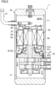
- the compressor (1) includes a casing (10), a, an electric motor (20), and a compression mechanism (30).
- the electric motor (20) and the compression mechanism (30) are housed in the casing (10).
- the compressor (1) is configured as a so-called high-pressure dome-shaped compressor where the refrigerant compressed in the compression mechanism (30) is discharged into the internal space (S) of the casing (10) and the pressure inside the internal space (S) becomes high.
- the refrigerant is a fluid of the present disclosure.
- the casing (10) is a closed container.
- the casing (10) includes a cylindrical barrel (11) extending in the top-to-bottom direction, an upper end plate (12) that closes an upper end of the barrel (11), a lower end plate (13) that closes a lower end of the barrel (11).
- the upper end plate (12) and the lower end plate are formed to be thick.
- the barrel (11) has, at its lower portion, a suction pipe (14).
- the upper end plate (12) has a discharge pipe (15) and a terminal (16) for supplying electric power to the electric motor (20).
- the casing (10) has, at is bottom, an oil reservoir (17).
- the oil reservoir (17) stores lubricant for lubricating sliding components inside the compression mechanism (30).
- a mounting plate (44) is fixed on substantially the middle of the inner peripheral surface of the barrel (11).
- the mounting plate (44) is a disk-shaped member.
- An oil passage through which the lubricant passes is provided in a portion of an outer edge of the mounting plate (44). The lubricant supplied to the sliding components passes through the oil passage and is again stored in the oil reservoir (17).
- the electric motor (20) is housed in the casing (10).
- the electric motor (20) drives the compression mechanism (30).
- the electric motor (20) is disposed above the mounting plate (44) inside the electric motor (20).
- the internal space (S) is partitioned into a first internal space (S1) in a lower portion of the electric motor (20) and a second internal space (S2) in an upper portion of the electric motor (20).
- the electric motor (20) has a tubular stator (21) along the inner peripheral surface of the barrel (11) and a rotor (22) disposed inside the stator (21).
- the stator (21) has a stator core (21a) and a stator coil (not shown).
- the stator core (21a) is a substantially tubular member.
- the stator core (21a) includes a single back yoke (27) and a plurality of teeth (28).
- the back yoke (27)) is an outer peripheral portion of the stator core (21a), and is annular when viewed in plan.
- the teeth (28) extend radially inward from the inner peripheral surface of the back yoke (27).
- the teeth (28) are arranged at predetermined pitches in the circumferential direction of the stator core (21a).
- Slots (29) for housing the stator coil (not shown) are provided between the circumferentially adjacent teeth (28).
- nine slots (29) including a first slot (29a) to a ninth slot (29i), are provided clockwise when the stator core (21a) is viewed from above.
- Core cuts (23) are provided in the outer peripheral surface of the stator core (21a). Specifically, the core cuts (23) are provided along the axial direction of the stator core (21a). Specifically, the core cuts (23) are each formed into a recessed groove shape recessed inward in the radial direction of the stator core (21a) between adjacent slots (29) in the circumferential direction. Each core cut (23) extends along the axial direction of the stator core (21a) from the lower end to the upper end of the stator core (21a).
- Fluid passages (24) are provided between the outer peripheral surface of the stator core (21a) and the inner peripheral surface of the barrel (11). Each fluid passage (24) extends from one end to the other end of the stator (21). A fluid discharged from the compression mechanism (30) flows through the fluid passage (24). The fluid passage (24) will be described in detail later.
- the compression mechanism (30) is housed in the casing (10).
- the compression mechanism (30) compresses a fluid sucked and discharges the compressed fluid into the internal space (S) of the casing (10).
- the compression mechanism (30) is disposed on the lower surface of the mounting plate (44), and is fastened with the mounting plate (44) and a bolt (73).
- the compression mechanism (30) includes a drive shaft (31), a first cylinder (34a), a second cylinder (34b), a front head (41), a middle plate (42), a rear head (43), a first piston (35a), and a second piston (35b).
- the drive shaft (31) is disposed to extend in the top-to-bottom direction in the casing (10).
- An upper portion of the drive shaft (31) is connected to a rotor (22) of the electric motor (20).
- a lower portion of the drive shaft (31) includes, in order from top to bottom, an upper shaft portion (31a), a first eccentric portion (32a), an intermediate shaft portion (31b), a second eccentric portion (32b), and a lower shaft portion (31c).
- the first eccentric portion (32a) and the second eccentric portion (32b) are eccentric with the shaft center of the drive shaft (31) so that the rotational phase difference is 180 degrees from each other.
- the first eccentric portion (32a) and the second eccentric portion (32b) are provided to have larger diameters than the upper shaft portion (31a), the intermediate shaft portion (31b), and the lower shaft portion (31c).
- An oil pump (61) is fixed to the lower end of the drive shaft (31).
- the oil pump (61) sucks lubricant in the oil reservoir (17).
- An oil supply passage (62) is provided inside the drive shaft (31).
- the oil supply passage (62) is a passage through which the lubricant sucked by the oil pump (61) flows.
- the oil supply passage (62) includes a main oil supply path (62a) and a plurality of oil supply openings (62b).
- the main oil supply path (62a) extends in the top-to-bottom direction, and the lower end of the main oil supply path (62a) communicates with the oil pump (61).
- the oil supply openings (62b) extend radially outward at the middle of the main oil supply path (62a), and the outer peripheral ends of the oil supply openings (62b) are open to the side surface of the drive shaft (31). With this configuration, the lubricant in the oil reservoir (17) is supplied to sliding portions of the drive shaft (31) and the pistons (35a, 35b).
- the first cylinder (34a) and the second cylinder (34b) are each formed into a substantially cylindrical shape.
- the shaft of the first cylinder (34a) and the shaft of the second cylinder (34b) extend in the top-to-bottom direction.
- the second cylinder (34b) is disposed below the first cylinder (34a).
- the first eccentric portion (32a) of the drive shaft (31) is inserted into the first cylinder (34a), and the second eccentric portion (32b) of the drive shaft (31) is inserted into the second cylinder (34b).
- the first piston (35a) is housed in the first cylinder (34a).
- the first piston (35a) is configured to slide to both a upper front head (41) and a lower middle plate (42).
- the first piston (35a) includes a first piston body (36a) and a first blade (37a).
- the first piston body (36a) is formed in an annular shape. Specifically, the first piston body (36a) is formed in a slightly thick cylindrical shape. The first eccentric portion (32a) of the drive shaft (31) is slidably inserted into the first piston body (36a). The first piston body (36a) is configured to revolve along the inner peripheral surface of the first cylinder (34a) when the drive shaft (31) rotates. A first compression chamber (50a) is provided between the first piston body (36a) and the first cylinder (34a).
- the first blade (37a) is integral with the first piston body (36a).
- the first blade (37a) protrudes radially outward from the outer peripheral surface of the first piston body (36a).
- the first blade (37a) is sandwiched between a pair of first swing bushes (54a, 54b) provided in a first bush groove (53a) extending radially outward from the inner peripheral surface of the first cylinder (34a).
- the first blade (37a) is configured to restrict rotation of the first piston body (36a) when the first piston body (36a) revolves.
- the first blade (37a) partitions the first compression chamber (50a) into a first low-pressure chamber (51a) and a first high-pressure chamber (52a).
- the first cylinder (34a) has a first suction port (55a) penetrating in the radial direction of the first cylinder (34a).
- the inner peripheral end of the first suction port (55a) communicates with the first low-pressure chamber (51a), and the outer peripheral end of the first suction port (55a) is connected to a first suction pipe (14a).
- the second piston (35b) is housed in the second cylinder (34b), and is configured to slide to both the upper middle plate (42) and the lower rear head (43). As shown in FIG. 2 , the second piston (35b) and the first piston (35a) have the same configuration. Specifically, the second piston (35b) has a second piston body (36b) and a second blade (37b).
- the second piston body (36b) is formed in an annular shape. Specifically, the second piston body (36b) is formed in a slightly thick cylindrical shape.
- the second eccentric portion (32b) of the drive shaft (31) is slidably inserted into the second piston body (36b).
- the second piston body (36b) is configured to revolve along the inner peripheral surface of the second cylinder (34b) when the drive shaft (31) rotates.
- a second compression chamber (50b) is provided between the second piston body (36b) and the second cylinder (34b).
- the second blade (37b) is integral with the second piston body (36b).
- the second blade (37b) protrudes radially outward from the outer peripheral surface of the second piston body (36b).
- the second blade (37b) is sandwiched between a pair of second swing bushes (54c, 54d) provided in a second bush groove (53b) extending radially outward from the inner peripheral surface of the second cylinder (34b).
- the second blade (37b) is configured to restrict rotation of the second piston body (36b) when the second piston body (36b) revolves.
- the second blade (37b) partitions the second compression chamber (50b) into a second low-pressure chamber (51b) and a second high-pressure chamber (52b).
- the second cylinder (34b) has a second suction port (55b) penetrating in the radial direction of the second cylinder (34b).
- the inner peripheral end of the second suction port (55b) communicates with the second low-pressure chamber (51b), and the outer peripheral end of the second suction port (55b) is connected to a second suction pipe (14b).
- the front head (41) is fastened to the upper end of a cylinder (34) with a bolt (73).
- the front head (41) closes the upper end of the cylinder (34).
- This front head (41) has an upper bearing (41a) and a first discharge valve (41i).
- the upper bearing (41a) is formed into a cylindrical shape.
- the upper bearing (41a) rotatably supports the upper shaft portion (31a) of the drive shaft (31).
- the first discharge valve (41i) is a valve provided at a discharge port (not shown) allowing the first high-pressure chamber (52a) and the first muffler chamber (R1) to be described later to communicate with each other.
- the first discharge valve (41i) is configured to open when the pressure of the refrigerant in the first high-pressure chamber (52a) reaches a predetermined value or higher.
- a front muffler (71) is fixed to the front head (41).
- the front muffler (71) is provided to cover the first discharge valve (41i).
- the first muffler chamber (R1) is provided between the front muffler (71) and the front head (41).
- the first muffler chamber (R1) communicates with the first high-pressure chamber (52a) and the second high-pressure chamber (52b).
- the front muffler (71) has a communication hole (not shown) allowing the first muffler chamber (R1) and the first internal space (S1) to communicate with each other.
- the middle plate (42) is fixed to the lower end of the first cylinder (34a) and the upper end of the second cylinder (34b) to close the lower end of the first cylinder (34a) and the upper end of the second cylinder (34b).
- the intermediate shaft portion (31b) of the drive shaft (31) is inserted into the middle plate (42).
- the rear head (43) is fastened to the lower end of the cylinder (34) with a bolt (not shown).
- the rear head (43) closes the lower end of the cylinder (34).
- the rear head (43) has a lower bearing (43a) and a second discharge valve (43d).
- the lower bearing (43a) is formed into a cylindrical shape.
- the lower bearing (43a) rotatably supports the lower shaft portion (31c) of the drive shaft (31).
- the second discharge valve (43d) is a valve provided at a discharge port (not shown) allowing the second high-pressure chamber (52b) and a second muffler chamber (R2) to communicate with each other.
- the second discharge valve (43d) is configured to open when the pressure of the refrigerant in the second high-pressure chamber (52b) reaches a predetermined value or higher.
- a rear muffler (72) is fixed to the rear head (43).
- the rear muffler (72) is provided to cover the second discharge valve (43d).
- the second muffler chamber (R2) is provided between the rear head (43) and the rear muffler (72).
- the second muffler chamber (R2) communicates with the first muffler chamber (R1) via a communication passage (not shown).
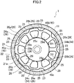
- the fluid passages (24) are provided between the outer peripheral surface of the stator core (21a) and the inner peripheral surface of the barrel (11).
- the fluid passage (24) will be described in detail below.
- Joint portions (45) are provided on the outer peripheral surface of the stator core (21a).
- the joint portions (45) are in contact with the inner peripheral surface of the barrel (11), and are joined to the barrel (11) by welding.
- the stator core (21a) of the present disclosure is provided with three joint portions (45) (a first joint portion (45a) to a third joint portion (45c)). Each joint portion (45) extends from one end to the other end of the stator core (21a).
- first joint portion (45a) is a portion of the outer peripheral surface of the stator core (21a) on the outside of the first joint portion (45a).
- the second joint portion (45b) is a portion of the outer peripheral surface of the stator core (21a) on the outside of the fourth slot (29d).
- the third joint portion (45c) is a portion of the outer peripheral surface of the stator core (21a) on the outside of the seventh slot (29g).
- the fluid passages (24) and the joint portions (45) are arranged alternately along the circumferential direction of the stator core (21a).
- the compressor (1) of the present disclosure is provided with three fluid passages (a first fluid passage (24a) to a third fluid passages (24c)).
- the first fluid passage (24a) is provided between the first joint portion (45a) and the second joint portion (45b).
- the second fluid passage (24b) is provided between the second joint portion (45b) and the third joint portion (45c).
- the third fluid passages (24c) is provided between the third joint portion (45c) and the first joint portion (45a).
- Each of the fluid passages (24a to 24c) has the same shape.
- each fluid passage (24) has three wide portions (25) and two narrow portions (26).
- the wide portions (25) are spaces between the respective core cuts (23) and the inner peripheral surface of the barrel (11) facing the core cuts.
- the narrow portions (26) are spaces between the inner peripheral surface of the barrel (11) and portions of the outer peripheral surface of the stator core (21a) on the outsides of the respective slots (29) except the first slot (29a), the fourth slot (29d), and the seventh slot (29g).
- Each narrow portion (26) is provided between adjacent wide portions (25). With this configuration, the wide portions (25) and the narrow portions (26) are arranged alternately along the circumferential direction of the stator core (21a).
- the two narrow portions (26) are provided so that the forward narrow portion (26) in the direction of rotation of the rotor (22) has a smaller width in the radial direction of the stator (21).
- one of the two narrow portions (26) is referred to as a first narrow portion (26a), and the other is referred to as the second narrow portion (26b).
- the second narrow portion (26b) is located forward of the first narrow portion (26a) in the clockwise direction when the electric motor (20) is viewed from above.
- the rotor (22) of the present disclosure rotates clockwise when the electric motor (20) is viewed from above.
- the width D2 of the second narrow portion (26b) in the radial direction is smaller than the width D1 of the first narrow portion (26a) in the radial direction.
- the first narrow portion (26a) is provided between the outer surface of the second slot (29b) and the inner peripheral surface of the barrel (11).
- the second narrow portion (26b) is provided between the outer surface of the third slot (29c) and the inner peripheral surface of the barrel (11).
- the width D1 of the first narrow portion (26a) in the radial direction is smaller than the width D3 of each of the wide portions (25) in the radial direction. Strictly speaking, the largest width D3 among the widths of the wide portions (25) in the radial direction is larger than the width D1 of the first narrow portion (26a) in the radial direction.
- each fluid passage (24), the wide portion (25), the first narrow portion (26a), the wide portion (25), the second narrow portion (26b), and the wide portion (25) are formed clockwise.
- the second fluid passage (24b) and the third fluid passage (24c) each have the same configuration as the first fluid passage (24a).
- a suction stroke of sucking the refrigerant into the first compression chamber (50a) will now be described below.
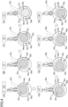
- the drive shaft (31) slightly rotates from the state (the state of (A) in FIG. 4 ) of the rotational angle of 0°, a contact portion between the first piston (35a) and the first cylinder (34a) passes by the inner peripheral end of the first suction port (55a).
- suction of the refrigerant into the first low-pressure chamber (51a) is started.
- the refrigerant is sucked through the first suction pipe (14a) via the first suction port (55a).
- the capacity of the first low-pressure chamber (51a) increases, thereby increasing the amount of the refrigerant sucked into the first low-pressure chamber (51a) (the states shown in (B) to (H) of FIG. 4 ).
- the suction stroke for the refrigerant continues until the rotational angle of the drive shaft (31) reaches 360°, and thereafter shifts to the discharge stroke.
- the suction stroke for the refrigerant in the second compression chamber (50b) is the same as the suction stroke in the first compression chamber (50a).
- the first low-pressure chamber (51a) in connection with the first suction port (55a) is changed to the first high-pressure chamber (52a) in connection with only the discharge port (not shown). From this state, the compression of the refrigerant in the first high-pressure chamber (52a) is started. With the increase in the rotational angle of the drive shaft (31), the capacity of the first high-pressure chamber (52a) decreases, and the pressure in the first high-pressure chamber (52a) increases. When the pressure in the first high-pressure chamber (52a) reaches a predetermined pressure or more, the discharge valve (41d) is open.
- the refrigerant in the first high-pressure chamber (52a) is discharged into the first muffler chamber (R1) via the discharge port (not shown). Also in the second compression chamber (50b), the same discharge stroke as in the first compression chamber (50a) is conducted.
- the refrigerant in the second high-pressure chamber (52b) is discharged into the second muffler chamber (R2) via the discharge port (not shown).
- the refrigerant discharged into the second muffler chamber (R2) passes through a communication passage (not shown), and merges with the refrigerant in the first muffler chamber (R1).
- the refrigerant in the first muffler chamber (R1) is discharged into the first internal space (S1).
- the refrigerant passes through the core cuts (23) and gaps between the stator (21) and the rotor (22), and flows into the second internal space (S2).
- the gas refrigerant that has flowed into the second internal space (S2) is discharged outside of the compressor (1) via the discharge pipe (15).
- the discharge stroke for the refrigerant continues until the rotational angle of the drive shaft (31) reaches 360°, and thereafter shifts to the suction stroke.
- each compression chamber (50a, 50b) in each compression chamber (50a, 50b), the suction stroke and the discharge stroke are alternately performed, whereby the operation of compressing the refrigerant is continuously performed.
- the refrigerant that has been compressed in the compression mechanism (30a, 30b) is discharged from the first muffler chamber (R1) to the internal space (S1).
- the pressure of the lubricant stored in the oil reservoir (17) of the casing (10) is substantially identical to the pressure of the high-pressure refrigerant discharged from the compression mechanism (30) to the internal space (S1) of the casing (10).
- the high-pressure lubricant in the oil reservoir (17) passes through the oil supply passage (62) of the drive shaft (31) and is supplied to the compression mechanism (30).
- the high-pressure lubricant that has been supplied to the compression mechanism (30) flows into a gap between the upper shaft portion (31a) and the drive shaft (31), the gap between the lower shaft portion (31c) and the drive shaft (31), a gap between the first eccentric portion (32a) and the first piston (35a), and a gap between the second eccentric portion (32b) and the second piston (35b).
- the high-pressure lubricant that has been supplied to the compression mechanism (30) also flows into a gap between the upper end surface of the first piston (35a) and the front head (41) and a gap between the lower end surface of the second piston (35b) and the rear head (43).
- part of the oil that has been supplied to the compression mechanism (30) is mixed with the refrigerant gas that has been discharged into the first internal space (S 1), and then flows into each fluid passage (24).
- the solid arrows in FIG. 5 indicate the flow of the lubricant, and the dotted arrows indicate the flow of the refrigerant gas.
- the arrows in FIG. 6 show the flows of the lubricant and the refrigerant gas.
- the rotor (22) rotates clockwise.
- the refrigerant gas that has flowed into the fluid passages (24) rises while flowing clockwise through the fluid passages (24).
- the refrigerant gas rises in the fluid passages (24) while flowing through the wide portion (25), the first narrow portion (26a), the wide portion (25), the second narrow portion (26b), and the wide portion (25) in this order.
- the refrigerant gas that has risen in the fluid passages (24) flows into the second internal space (S2), and flows out of the compressor (1) through the discharge pipe (15).
- the lubricant that has supplied to each sliding portion of the compression mechanism flows from the first internal space (S1) into the second internal space (S2) through core cuts (23), the stator core (21a), and the rotor (22), together with the refrigerant gas discharged from the compression mechanism to the first internal space (S 1).
- the lubricant that has been rolled up by the refrigerant gas and flowed into the second internal space (S2) drops through the core cuts (23) due to its own weight and is stored in the oil reservoir (17).
- the refrigerant gas flows at a high flow velocity
- the lubricant is rolled up by the refrigerant gas and is less likely to return to the oil reservoir (17).
- part of the lubricant tends to flow out of the compressor through the discharge pipe together with the refrigerant gas.
- the amount of the lubricant stored in the compressor (1) may become too small.
- fluid passages (24) each extending from one end to the other end of the stator (21) and through which the fluid discharged from the compression mechanism (30) pass are provided between the outer peripheral surface of the stator (21) and the inner peripheral surface of the barrel (11).
- Each fluid passage (24) includes a plurality of wide portions (25) arranged in the circumferential direction of the stator (21) and narrow portions (26) which are provided between adjacent wide portions (25) and each have a width in the radial direction of the stator (21) smaller than those of the wide portions (25).
- each narrow portion (26) has a smaller width in the radial direction of the stator (21) than each wide portion (25).
- the lubricant having a specific gravity larger than the refrigerant gas cannot rapidly decelerate and thus is easily separated from the refrigerant gas.
- the separated refrigerant gas collides with the wall surfaces or the like of the core cuts (23), drops along the inner peripheral surfaces of the core cuts (23) and the barrel (11), and easily returns to the oil reservoir (17). This can reduce the amount of the lubricant that does not return to the oil reservoir (17) but is rolled up again into the internal space (S) by the refrigerant gas, and further reduce the amount of the lubricant flowing out of the compressor (1) together with the refrigerant gas.
- the wide portions (25) and the narrow portions (26) are provided alternately in the circumferential direction of the stator (21).
- the refrigerant gas flowing through the fluid passages (24) repeatedly accelerated and decelerated. This can reliably promote separation of the lubricant from the refrigerant gas.
- joint portions (45) extending from one end to the other end of the stator (21) and in contact with the inner peripheral surface of the barrel (11) are provided.
- the joint portions (45) are in contact with the inner peripheral surface of the barrel (11).
- the flow of the refrigerant gas through the fluid passages (24) is blocked.
- This causes the refrigerant gas flowing in the circumferential direction of the stator (21) to collide with the core cuts (23) adjacent to the joint portions (45), so that the lubricant contained in the refrigerant gas adheres to the wall surface and is easily separated from the refrigerant gas.
- the fluid passages (24) and the joint portions (45) are arranged alternately along the circumferential direction of the stator (21).
- the fluid passage (24) can be provided between portions of the joint portion (45) adjacent in the circumferential direction of the stator (21).
- a plurality of fluid passage (24) are provided in the circumferential direction of the stator core (21a).
- the fluid passages (24) each have two or more narrow portions (26), and the two or more narrow portions (26) are provided so that the forward narrow portion (26) in the direction of rotation of the rotor (22) has a smaller width in the radial direction of the stator (21).
- a pressure loss occurs in the refrigerant gas containing lubricant by an amount corresponding to the deceleration of the refrigerant gas flowing from the wide portions (25) to the narrow portion (26).
- the narrow portions (26) are designed to be relatively narrow, the pressure loss of the refrigerant gas increases.
- the upstream refrigerant gas contains relatively large oil droplets.
- the widths of narrow portions (26) in the radial direction, at an upstream (front) side of the direction of rotation of the rotor (22) are designed to be relatively larger. This allows a reduction in pressure loss of the refrigerant gas.
- the oil droplets contained in the refrigerant gas flowing in the direction of rotation of the rotor (22) become smaller as they flow from the narrow portions (26) to the wide portions (25).
- the lubricant is easily separated from the refrigerant gas, and the pressure loss occurred in the refrigerant gas can be reduced.
- a decrease in the compressor efficiency due to the increase in the pressure loss of the refrigerant gas is reduced, and the reduction in the compressor efficiency can be reduced.
- the number of joint portions (45) is not limited to three.
- the number of joint portions (45) provided on the outer peripheral surface of the stator core (21a) may be two or less, or four or more.
- the joint portions (45) do not have to be arranged at equal intervals in the circumferential direction of the stator core (21a).
- the joint portions (45) may be provided only in a portion from one end to the other end of the stator core (21a).
- the joint portions (45) do not have to be parts of the outer peripheral surface of the stator core (21a).
- the joint portions (45) may be members provided separately.
- the number of fluid passages (24) is not limited to three.
- the number of fluid passages (24) may be one, two or more, or four or more.
- each fluid passage (24) The number of wide portions (25) and narrow portions (26) provided in each fluid passage (24) is not limited. In the fluid passage (24), the wide portion (25) and the narrow portion (26) may be adjacent to each other in the direction of rotation of the rotor (22).
- narrow portions (26) When three or more narrow portions (26) are provided inside the fluid passage (24), only some of the narrow portions (26) may be provided such that, the further forward the narrow portion (26) is in the direction of rotation of the rotor, the narrower its width in the radial direction of the stator (21) is. All narrow portions (26) may have the same width in the radial direction of the stator (21).
- the outer peripheral surface of the stator core (21a) forming the narrow portions (26) do not have to be formed along the inner peripheral surface of the barrel (11).
- the outer peripheral surface may be formed to be inclined when the stator core (21a) is viewed from above, or may be formed in a wave shape.
- the compression mechanism of the compressor (1) may be a single cylinder compression mechanism including a pair of cylinders and a piston.
- the compressor (1) may be a scroll compressor.
- adjacent narrow portions (26, 26) may have different widths in the radial direction of the stator (21).
- a plurality of narrow portions (26, 26, ..., 26) may be provided such that their widths in the radial direction of the stator (21) increase toward the direction of rotation of the rotor (22).
- the second narrow portion (26b) may have a larger width in the radial direction of the stator (21) than the first narrow portion (26a).
- each narrow portion (26) in the radial direction of the stator (21) may be wide enough to allow the refrigerant to circulate through the narrow portion (26) when the rotor (22) rotates.
- the width of the narrow portion (26) in the radial direction of the stator (21) may be 0.1 mm or more, preferably 1 mm or more.
- the width of the narrow portion (26) in the radial direction of the stator (21) is 1/9 to 2/3 of the width of each wide portion (25) in the radial direction of the stator (21).
- the present disclosure is useful for a compressor.
Landscapes
- Engineering & Computer Science (AREA)
- Mechanical Engineering (AREA)
- General Engineering & Computer Science (AREA)
- Applications Or Details Of Rotary Compressors (AREA)
- Compressor (AREA)
Applications Claiming Priority (2)
| Application Number | Priority Date | Filing Date | Title |
|---|---|---|---|
| JP2020113304 | 2020-06-30 | ||
| PCT/JP2021/021618 WO2022004288A1 (fr) | 2020-06-30 | 2021-06-07 | Compresseur |
Publications (3)
| Publication Number | Publication Date |
|---|---|
| EP4148276A1 true EP4148276A1 (fr) | 2023-03-15 |
| EP4148276A4 EP4148276A4 (fr) | 2023-11-08 |
| EP4148276B1 EP4148276B1 (fr) | 2025-05-21 |
Family
ID=79193126
Family Applications (1)
| Application Number | Title | Priority Date | Filing Date |
|---|---|---|---|
| EP21833778.0A Active EP4148276B1 (fr) | 2020-06-30 | 2021-06-07 | Compresseur |
Country Status (6)
| Country | Link |
|---|---|
| US (1) | US12049888B2 (fr) |
| EP (1) | EP4148276B1 (fr) |
| JP (1) | JP6985639B1 (fr) |
| CN (1) | CN115735062B (fr) |
| ES (1) | ES3033089T3 (fr) |
| WO (1) | WO2022004288A1 (fr) |
Families Citing this family (1)
| Publication number | Priority date | Publication date | Assignee | Title |
|---|---|---|---|---|
| JP7436903B1 (ja) * | 2022-10-20 | 2024-02-22 | ダイキン工業株式会社 | 圧縮機 |
Family Cites Families (19)
| Publication number | Priority date | Publication date | Assignee | Title |
|---|---|---|---|---|
| JPH024991U (fr) * | 1988-06-24 | 1990-01-12 | ||
| JP3420641B2 (ja) * | 1994-08-23 | 2003-06-30 | 東芝キヤリア株式会社 | 密閉形圧縮機 |
| JP3855504B2 (ja) * | 1998-12-14 | 2006-12-13 | 株式会社デンソー | 密閉型電動圧縮機 |
| TW564285B (en) * | 1999-06-29 | 2003-12-01 | Sanyo Electric Co | Sealed rotary compressor |
| JP3555611B2 (ja) * | 2002-01-30 | 2004-08-18 | ダイキン工業株式会社 | 密閉型圧縮機 |
| JP3818213B2 (ja) * | 2002-05-01 | 2006-09-06 | 株式会社デンソー | 電動圧縮機 |
| JP4036148B2 (ja) * | 2002-07-23 | 2008-01-23 | 株式会社豊田自動織機 | 電動モータ及び電動コンプレッサ |
| JP2004201428A (ja) * | 2002-12-19 | 2004-07-15 | Matsushita Electric Ind Co Ltd | 電動機 |
| JP4269907B2 (ja) * | 2003-11-21 | 2009-05-27 | 株式会社豊田自動織機 | 密閉型電動圧縮機におけるステータコアの組み付け方法 |
| JP5050393B2 (ja) * | 2006-04-19 | 2012-10-17 | ダイキン工業株式会社 | 圧縮機 |
| JP4483895B2 (ja) * | 2007-05-01 | 2010-06-16 | ダイキン工業株式会社 | 回転電機及び圧縮機 |
| JP4251239B2 (ja) | 2007-07-25 | 2009-04-08 | ダイキン工業株式会社 | 密閉式圧縮機 |
| JP4758484B2 (ja) * | 2008-01-24 | 2011-08-31 | ダイキン工業株式会社 | 圧縮機 |
| JP6233726B2 (ja) * | 2013-10-15 | 2017-11-22 | パナソニックIpマネジメント株式会社 | 圧縮機 |
| JP6345099B2 (ja) * | 2014-12-08 | 2018-06-20 | 日立ジョンソンコントロールズ空調株式会社 | 密閉型電動圧縮機及び空気調和機 |
| KR101940682B1 (ko) * | 2015-04-07 | 2019-01-22 | 엘지이노텍 주식회사 | 스테이터 및 이를 포함하는 모터 |
| JP6686615B2 (ja) * | 2016-03-28 | 2020-04-22 | 株式会社富士通ゼネラル | ロータリ圧縮機 |
| EP3522337B1 (fr) * | 2016-09-29 | 2021-10-27 | Mitsubishi Electric Corporation | Rotor, moteur rotatif et compresseur |
| JP2019015241A (ja) * | 2017-07-07 | 2019-01-31 | ダイキン工業株式会社 | 圧縮機 |
-
2021
- 2021-06-07 ES ES21833778T patent/ES3033089T3/es active Active
- 2021-06-07 CN CN202180045786.7A patent/CN115735062B/zh active Active
- 2021-06-07 JP JP2021095044A patent/JP6985639B1/ja active Active
- 2021-06-07 EP EP21833778.0A patent/EP4148276B1/fr active Active
- 2021-06-07 WO PCT/JP2021/021618 patent/WO2022004288A1/fr not_active Ceased
-
2022
- 2022-12-28 US US18/090,301 patent/US12049888B2/en active Active
Also Published As
| Publication number | Publication date |
|---|---|
| CN115735062A (zh) | 2023-03-03 |
| US20230160383A1 (en) | 2023-05-25 |
| WO2022004288A1 (fr) | 2022-01-06 |
| JP2022013732A (ja) | 2022-01-18 |
| JP6985639B1 (ja) | 2021-12-22 |
| US12049888B2 (en) | 2024-07-30 |
| ES3033089T3 (en) | 2025-07-30 |
| EP4148276B1 (fr) | 2025-05-21 |
| EP4148276A4 (fr) | 2023-11-08 |
| CN115735062B (zh) | 2024-04-05 |
Similar Documents
| Publication | Publication Date | Title |
|---|---|---|
| US9624928B2 (en) | Scroll-type compressor with gas passage formed in orbiting plate to restrict flow from compression chamber to back pressure chamber | |
| EP2078861B1 (fr) | Compresseur rotatif à deux étages | |
| RU2600206C1 (ru) | Спиральный компрессор | |
| US9512842B2 (en) | Rotary compressor | |
| CN212155151U (zh) | 旋转式压缩机 | |
| US7390179B2 (en) | Scroll machine having counterweights with changeable cavity | |
| US11703052B2 (en) | High pressure scroll compressor | |
| EP2803863A1 (fr) | Compresseur du type à palettes | |
| CN111133197A (zh) | 涡旋式压缩机 | |
| US12049888B2 (en) | Compressor | |
| JP6302428B2 (ja) | シリンダ回転型圧縮機 | |
| EP3647595A1 (fr) | Compresseur rotatif | |
| JP6742499B2 (ja) | 電動圧縮機 | |
| US11668308B2 (en) | Compressor having sliding portion provided with oil retainer | |
| JP7502638B2 (ja) | ロータリ圧縮機 | |
| EP3647596B1 (fr) | Compresseur rotatif | |
| JP2014214736A (ja) | スクロール流体機械 | |
| EP3604818A1 (fr) | Compresseur du type à piston oscillant | |
| JP5201045B2 (ja) | 2段圧縮ロータリ圧縮機 | |
| WO2016157688A1 (fr) | Compresseur du type à cylindre rotatif | |
| CN114222861A (zh) | 涡旋压缩机 | |
| JP2022011909A (ja) | 圧縮機 | |
| EP4056849B1 (fr) | Compresseur | |
| CN219327627U (zh) | 涡旋压缩机 | |
| JP2014020209A (ja) | 2段圧縮機および2段圧縮システム |
Legal Events
| Date | Code | Title | Description |
|---|---|---|---|
| STAA | Information on the status of an ep patent application or granted ep patent |
Free format text: STATUS: THE INTERNATIONAL PUBLICATION HAS BEEN MADE |
|
| PUAI | Public reference made under article 153(3) epc to a published international application that has entered the european phase |
Free format text: ORIGINAL CODE: 0009012 |
|
| STAA | Information on the status of an ep patent application or granted ep patent |
Free format text: STATUS: REQUEST FOR EXAMINATION WAS MADE |
|
| 17P | Request for examination filed |
Effective date: 20221207 |
|
| AK | Designated contracting states |
Kind code of ref document: A1 Designated state(s): AL AT BE BG CH CY CZ DE DK EE ES FI FR GB GR HR HU IE IS IT LI LT LU LV MC MK MT NL NO PL PT RO RS SE SI SK SM TR |
|
| P01 | Opt-out of the competence of the unified patent court (upc) registered |
Effective date: 20230525 |
|
| DAV | Request for validation of the european patent (deleted) | ||
| DAX | Request for extension of the european patent (deleted) | ||
| A4 | Supplementary search report drawn up and despatched |
Effective date: 20231009 |
|
| RIC1 | Information provided on ipc code assigned before grant |
Ipc: F04C 29/00 20060101ALI20231002BHEP Ipc: F04B 39/04 20060101ALI20231002BHEP Ipc: F04C 29/02 20060101AFI20231002BHEP |
|
| STAA | Information on the status of an ep patent application or granted ep patent |
Free format text: STATUS: EXAMINATION IS IN PROGRESS |
|
| 17Q | First examination report despatched |
Effective date: 20240708 |
|
| GRAP | Despatch of communication of intention to grant a patent |
Free format text: ORIGINAL CODE: EPIDOSNIGR1 |
|
| STAA | Information on the status of an ep patent application or granted ep patent |
Free format text: STATUS: GRANT OF PATENT IS INTENDED |
|
| INTG | Intention to grant announced |
Effective date: 20250221 |
|
| GRAS | Grant fee paid |
Free format text: ORIGINAL CODE: EPIDOSNIGR3 |
|
| GRAA | (expected) grant |
Free format text: ORIGINAL CODE: 0009210 |
|
| STAA | Information on the status of an ep patent application or granted ep patent |
Free format text: STATUS: THE PATENT HAS BEEN GRANTED |
|
| RAP3 | Party data changed (applicant data changed or rights of an application transferred) |
Owner name: DAIKIN INDUSTRIES, LTD. |
|
| RIN1 | Information on inventor provided before grant (corrected) |
Inventor name: UEDA, HITOSHI Inventor name: OKAMOTO, DAISUKE Inventor name: ADACHI, MASAAKI Inventor name: TOMIOKA, NAOTO Inventor name: NISHIDE, YOUHEI Inventor name: KAJIWARA, MIKIO Inventor name: OHNISHI, YOUSUKE |
|
| AK | Designated contracting states |
Kind code of ref document: B1 Designated state(s): AL AT BE BG CH CY CZ DE DK EE ES FI FR GB GR HR HU IE IS IT LI LT LU LV MC MK MT NL NO PL PT RO RS SE SI SK SM TR |
|
| REG | Reference to a national code |
Ref country code: GB Ref legal event code: FG4D |
|
| REG | Reference to a national code |
Ref country code: CH Ref legal event code: EP |
|
| REG | Reference to a national code |
Ref country code: DE Ref legal event code: R096 Ref document number: 602021031241 Country of ref document: DE |
|
| REG | Reference to a national code |
Ref country code: IE Ref legal event code: FG4D |
|
| PGFP | Annual fee paid to national office [announced via postgrant information from national office to epo] |
Ref country code: AT Payment date: 20250721 Year of fee payment: 5 |
|
| REG | Reference to a national code |
Ref country code: ES Ref legal event code: FG2A Ref document number: 3033089 Country of ref document: ES Kind code of ref document: T3 Effective date: 20250730 |
|
| REG | Reference to a national code |
Ref country code: NL Ref legal event code: MP Effective date: 20250521 |
|
| PG25 | Lapsed in a contracting state [announced via postgrant information from national office to epo] |
Ref country code: FI Free format text: LAPSE BECAUSE OF FAILURE TO SUBMIT A TRANSLATION OF THE DESCRIPTION OR TO PAY THE FEE WITHIN THE PRESCRIBED TIME-LIMIT Effective date: 20250521 Ref country code: PT Free format text: LAPSE BECAUSE OF FAILURE TO SUBMIT A TRANSLATION OF THE DESCRIPTION OR TO PAY THE FEE WITHIN THE PRESCRIBED TIME-LIMIT Effective date: 20250922 |
|
| PGFP | Annual fee paid to national office [announced via postgrant information from national office to epo] |
Ref country code: ES Payment date: 20250731 Year of fee payment: 5 |
|
| REG | Reference to a national code |
Ref country code: LT Ref legal event code: MG9D |
|
| PG25 | Lapsed in a contracting state [announced via postgrant information from national office to epo] |
Ref country code: NO Free format text: LAPSE BECAUSE OF FAILURE TO SUBMIT A TRANSLATION OF THE DESCRIPTION OR TO PAY THE FEE WITHIN THE PRESCRIBED TIME-LIMIT Effective date: 20250821 Ref country code: GR Free format text: LAPSE BECAUSE OF FAILURE TO SUBMIT A TRANSLATION OF THE DESCRIPTION OR TO PAY THE FEE WITHIN THE PRESCRIBED TIME-LIMIT Effective date: 20250822 |
|
| PG25 | Lapsed in a contracting state [announced via postgrant information from national office to epo] |
Ref country code: NL Free format text: LAPSE BECAUSE OF FAILURE TO SUBMIT A TRANSLATION OF THE DESCRIPTION OR TO PAY THE FEE WITHIN THE PRESCRIBED TIME-LIMIT Effective date: 20250521 Ref country code: PL Free format text: LAPSE BECAUSE OF FAILURE TO SUBMIT A TRANSLATION OF THE DESCRIPTION OR TO PAY THE FEE WITHIN THE PRESCRIBED TIME-LIMIT Effective date: 20250521 |
|
| PG25 | Lapsed in a contracting state [announced via postgrant information from national office to epo] |
Ref country code: BG Free format text: LAPSE BECAUSE OF FAILURE TO SUBMIT A TRANSLATION OF THE DESCRIPTION OR TO PAY THE FEE WITHIN THE PRESCRIBED TIME-LIMIT Effective date: 20250521 |
|
| PG25 | Lapsed in a contracting state [announced via postgrant information from national office to epo] |
Ref country code: HR Free format text: LAPSE BECAUSE OF FAILURE TO SUBMIT A TRANSLATION OF THE DESCRIPTION OR TO PAY THE FEE WITHIN THE PRESCRIBED TIME-LIMIT Effective date: 20250521 |
|
| PG25 | Lapsed in a contracting state [announced via postgrant information from national office to epo] |
Ref country code: RS Free format text: LAPSE BECAUSE OF FAILURE TO SUBMIT A TRANSLATION OF THE DESCRIPTION OR TO PAY THE FEE WITHIN THE PRESCRIBED TIME-LIMIT Effective date: 20250821 |
|
| PG25 | Lapsed in a contracting state [announced via postgrant information from national office to epo] |
Ref country code: IS Free format text: LAPSE BECAUSE OF FAILURE TO SUBMIT A TRANSLATION OF THE DESCRIPTION OR TO PAY THE FEE WITHIN THE PRESCRIBED TIME-LIMIT Effective date: 20250921 |
|
| PG25 | Lapsed in a contracting state [announced via postgrant information from national office to epo] |
Ref country code: LV Free format text: LAPSE BECAUSE OF FAILURE TO SUBMIT A TRANSLATION OF THE DESCRIPTION OR TO PAY THE FEE WITHIN THE PRESCRIBED TIME-LIMIT Effective date: 20250521 |
|
| REG | Reference to a national code |
Ref country code: AT Ref legal event code: MK05 Ref document number: 1796954 Country of ref document: AT Kind code of ref document: T Effective date: 20250521 |
|
| PG25 | Lapsed in a contracting state [announced via postgrant information from national office to epo] |
Ref country code: AT Free format text: LAPSE BECAUSE OF FAILURE TO SUBMIT A TRANSLATION OF THE DESCRIPTION OR TO PAY THE FEE WITHIN THE PRESCRIBED TIME-LIMIT Effective date: 20250521 Ref country code: SM Free format text: LAPSE BECAUSE OF FAILURE TO SUBMIT A TRANSLATION OF THE DESCRIPTION OR TO PAY THE FEE WITHIN THE PRESCRIBED TIME-LIMIT Effective date: 20250521 Ref country code: DK Free format text: LAPSE BECAUSE OF FAILURE TO SUBMIT A TRANSLATION OF THE DESCRIPTION OR TO PAY THE FEE WITHIN THE PRESCRIBED TIME-LIMIT Effective date: 20250521 |
|
| PG25 | Lapsed in a contracting state [announced via postgrant information from national office to epo] |
Ref country code: CZ Free format text: LAPSE BECAUSE OF FAILURE TO SUBMIT A TRANSLATION OF THE DESCRIPTION OR TO PAY THE FEE WITHIN THE PRESCRIBED TIME-LIMIT Effective date: 20250521 |
|
| PG25 | Lapsed in a contracting state [announced via postgrant information from national office to epo] |
Ref country code: EE Free format text: LAPSE BECAUSE OF FAILURE TO SUBMIT A TRANSLATION OF THE DESCRIPTION OR TO PAY THE FEE WITHIN THE PRESCRIBED TIME-LIMIT Effective date: 20250521 |
|
| PG25 | Lapsed in a contracting state [announced via postgrant information from national office to epo] |
Ref country code: SK Free format text: LAPSE BECAUSE OF FAILURE TO SUBMIT A TRANSLATION OF THE DESCRIPTION OR TO PAY THE FEE WITHIN THE PRESCRIBED TIME-LIMIT Effective date: 20250521 |
|
| REG | Reference to a national code |
Ref country code: CH Ref legal event code: H13 Free format text: ST27 STATUS EVENT CODE: U-0-0-H10-H13 (AS PROVIDED BY THE NATIONAL OFFICE) Effective date: 20260127 |
|
| PG25 | Lapsed in a contracting state [announced via postgrant information from national office to epo] |
Ref country code: RO Free format text: LAPSE BECAUSE OF FAILURE TO SUBMIT A TRANSLATION OF THE DESCRIPTION OR TO PAY THE FEE WITHIN THE PRESCRIBED TIME-LIMIT Effective date: 20250521 |
|
| PG25 | Lapsed in a contracting state [announced via postgrant information from national office to epo] |
Ref country code: LU Free format text: LAPSE BECAUSE OF NON-PAYMENT OF DUE FEES Effective date: 20250607 |
|
| PG25 | Lapsed in a contracting state [announced via postgrant information from national office to epo] |
Ref country code: MC Free format text: LAPSE BECAUSE OF FAILURE TO SUBMIT A TRANSLATION OF THE DESCRIPTION OR TO PAY THE FEE WITHIN THE PRESCRIBED TIME-LIMIT Effective date: 20250521 |
|
| REG | Reference to a national code |
Ref country code: DE Ref legal event code: R097 Ref document number: 602021031241 Country of ref document: DE |
|
| REG | Reference to a national code |
Ref country code: BE Ref legal event code: MM Effective date: 20250630 |
|
| PLBE | No opposition filed within time limit |
Free format text: ORIGINAL CODE: 0009261 |
|
| STAA | Information on the status of an ep patent application or granted ep patent |
Free format text: STATUS: NO OPPOSITION FILED WITHIN TIME LIMIT |
|
| REG | Reference to a national code |
Ref country code: CH Ref legal event code: L10 Free format text: ST27 STATUS EVENT CODE: U-0-0-L10-L00 (AS PROVIDED BY THE NATIONAL OFFICE) Effective date: 20260402 |
|
| PG25 | Lapsed in a contracting state [announced via postgrant information from national office to epo] |
Ref country code: IE Free format text: LAPSE BECAUSE OF NON-PAYMENT OF DUE FEES Effective date: 20250607 |
|
| PG25 | Lapsed in a contracting state [announced via postgrant information from national office to epo] |
Ref country code: BE Free format text: LAPSE BECAUSE OF NON-PAYMENT OF DUE FEES Effective date: 20250630 |
|
| PG25 | Lapsed in a contracting state [announced via postgrant information from national office to epo] |
Ref country code: CH Free format text: LAPSE BECAUSE OF NON-PAYMENT OF DUE FEES Effective date: 20250630 |
|
| 26N | No opposition filed |
Effective date: 20260224 |
|
| PG25 | Lapsed in a contracting state [announced via postgrant information from national office to epo] |
Ref country code: LT Free format text: LAPSE BECAUSE OF FAILURE TO SUBMIT A TRANSLATION OF THE DESCRIPTION OR TO PAY THE FEE WITHIN THE PRESCRIBED TIME-LIMIT Effective date: 20250521 |
|
| PGFP | Annual fee paid to national office [announced via postgrant information from national office to epo] |
Ref country code: GB Payment date: 20260505 Year of fee payment: 6 |
|
| PGFP | Annual fee paid to national office [announced via postgrant information from national office to epo] |
Ref country code: IT Payment date: 20260522 Year of fee payment: 6 |
|
| PGFP | Annual fee paid to national office [announced via postgrant information from national office to epo] |
Ref country code: DE Payment date: 20260430 Year of fee payment: 6 |
|
| PGFP | Annual fee paid to national office [announced via postgrant information from national office to epo] |
Ref country code: FR Payment date: 20260511 Year of fee payment: 6 |
|
| PG25 | Lapsed in a contracting state [announced via postgrant information from national office to epo] |
Ref country code: CY Free format text: LAPSE BECAUSE OF FAILURE TO SUBMIT A TRANSLATION OF THE DESCRIPTION OR TO PAY THE FEE WITHIN THE PRESCRIBED TIME-LIMIT Effective date: 20250521 Ref country code: SE Free format text: LAPSE BECAUSE OF FAILURE TO SUBMIT A TRANSLATION OF THE DESCRIPTION OR TO PAY THE FEE WITHIN THE PRESCRIBED TIME-LIMIT Effective date: 20250521 |