EP4148441A1 - Dispositif et procédé de gestion de batterie - Google Patents
Dispositif et procédé de gestion de batterie Download PDFInfo
- Publication number
- EP4148441A1 EP4148441A1 EP21856136.3A EP21856136A EP4148441A1 EP 4148441 A1 EP4148441 A1 EP 4148441A1 EP 21856136 A EP21856136 A EP 21856136A EP 4148441 A1 EP4148441 A1 EP 4148441A1
- Authority
- EP
- European Patent Office
- Prior art keywords
- soc
- profile
- ocv
- battery
- control unit
- Prior art date
- Legal status (The legal status is an assumption and is not a legal conclusion. Google has not performed a legal analysis and makes no representation as to the accuracy of the status listed.)
- Pending
Links
Images
Classifications
-
- G—PHYSICS
- G01—MEASURING; TESTING
- G01R—MEASURING ELECTRIC VARIABLES; MEASURING MAGNETIC VARIABLES
- G01R31/00—Arrangements for testing electric properties; Arrangements for locating electric faults; Arrangements for electrical testing characterised by what is being tested not provided for elsewhere
- G01R31/36—Arrangements for testing, measuring or monitoring the electrical condition of accumulators or electric batteries, e.g. capacity or state of charge [SoC]
- G01R31/367—Software therefor, e.g. for battery testing using modelling or look-up tables
-
- G—PHYSICS
- G01—MEASURING; TESTING
- G01R—MEASURING ELECTRIC VARIABLES; MEASURING MAGNETIC VARIABLES
- G01R31/00—Arrangements for testing electric properties; Arrangements for locating electric faults; Arrangements for electrical testing characterised by what is being tested not provided for elsewhere
- G01R31/36—Arrangements for testing, measuring or monitoring the electrical condition of accumulators or electric batteries, e.g. capacity or state of charge [SoC]
- G01R31/3644—Constructional arrangements
- G01R31/3648—Constructional arrangements comprising digital calculation means, e.g. for performing an algorithm
-
- G—PHYSICS
- G01—MEASURING; TESTING
- G01R—MEASURING ELECTRIC VARIABLES; MEASURING MAGNETIC VARIABLES
- G01R31/00—Arrangements for testing electric properties; Arrangements for locating electric faults; Arrangements for electrical testing characterised by what is being tested not provided for elsewhere
- G01R31/36—Arrangements for testing, measuring or monitoring the electrical condition of accumulators or electric batteries, e.g. capacity or state of charge [SoC]
- G01R31/382—Arrangements for monitoring battery or accumulator variables, e.g. SoC
-
- G—PHYSICS
- G01—MEASURING; TESTING
- G01R—MEASURING ELECTRIC VARIABLES; MEASURING MAGNETIC VARIABLES
- G01R31/00—Arrangements for testing electric properties; Arrangements for locating electric faults; Arrangements for electrical testing characterised by what is being tested not provided for elsewhere
- G01R31/36—Arrangements for testing, measuring or monitoring the electrical condition of accumulators or electric batteries, e.g. capacity or state of charge [SoC]
- G01R31/382—Arrangements for monitoring battery or accumulator variables, e.g. SoC
- G01R31/3842—Arrangements for monitoring battery or accumulator variables, e.g. SoC combining voltage and current measurements
-
- H—ELECTRICITY
- H01—ELECTRIC ELEMENTS
- H01M—PROCESSES OR MEANS, e.g. BATTERIES, FOR THE DIRECT CONVERSION OF CHEMICAL ENERGY INTO ELECTRICAL ENERGY
- H01M10/00—Secondary cells; Manufacture thereof
- H01M10/42—Methods or arrangements for servicing or maintenance of secondary cells or secondary half-cells
- H01M10/48—Accumulators combined with arrangements for measuring, testing or indicating the condition of cells, e.g. the level or density of the electrolyte
-
- B—PERFORMING OPERATIONS; TRANSPORTING
- B60—VEHICLES IN GENERAL
- B60L—PROPULSION OF ELECTRICALLY-PROPELLED VEHICLES; SUPPLYING ELECTRIC POWER FOR AUXILIARY EQUIPMENT OF ELECTRICALLY-PROPELLED VEHICLES; ELECTRODYNAMIC BRAKE SYSTEMS FOR VEHICLES IN GENERAL; MAGNETIC SUSPENSION OR LEVITATION FOR VEHICLES; MONITORING OPERATING VARIABLES OF ELECTRICALLY-PROPELLED VEHICLES; ELECTRIC SAFETY DEVICES FOR ELECTRICALLY-PROPELLED VEHICLES
- B60L58/00—Methods or circuit arrangements for monitoring or controlling batteries or fuel cells, specially adapted for electric vehicles
- B60L58/10—Methods or circuit arrangements for monitoring or controlling batteries or fuel cells, specially adapted for electric vehicles for monitoring or controlling batteries
- B60L58/12—Methods or circuit arrangements for monitoring or controlling batteries or fuel cells, specially adapted for electric vehicles for monitoring or controlling batteries responding to state of charge [SoC]
-
- G—PHYSICS
- G01—MEASURING; TESTING
- G01R—MEASURING ELECTRIC VARIABLES; MEASURING MAGNETIC VARIABLES
- G01R31/00—Arrangements for testing electric properties; Arrangements for locating electric faults; Arrangements for electrical testing characterised by what is being tested not provided for elsewhere
- G01R31/36—Arrangements for testing, measuring or monitoring the electrical condition of accumulators or electric batteries, e.g. capacity or state of charge [SoC]
- G01R31/374—Arrangements for testing, measuring or monitoring the electrical condition of accumulators or electric batteries, e.g. capacity or state of charge [SoC] with means for correcting the measurement for temperature or ageing
-
- H—ELECTRICITY
- H01—ELECTRIC ELEMENTS
- H01M—PROCESSES OR MEANS, e.g. BATTERIES, FOR THE DIRECT CONVERSION OF CHEMICAL ENERGY INTO ELECTRICAL ENERGY
- H01M10/00—Secondary cells; Manufacture thereof
- H01M10/42—Methods or arrangements for servicing or maintenance of secondary cells or secondary half-cells
- H01M10/425—Structural combination with electronic components, e.g. electronic circuits integrated to the outside of the casing
- H01M2010/4271—Battery management systems including electronic circuits, e.g. control of current or voltage to keep battery in healthy state, cell balancing
-
- H—ELECTRICITY
- H01—ELECTRIC ELEMENTS
- H01M—PROCESSES OR MEANS, e.g. BATTERIES, FOR THE DIRECT CONVERSION OF CHEMICAL ENERGY INTO ELECTRICAL ENERGY
- H01M10/00—Secondary cells; Manufacture thereof
- H01M10/42—Methods or arrangements for servicing or maintenance of secondary cells or secondary half-cells
- H01M10/425—Structural combination with electronic components, e.g. electronic circuits integrated to the outside of the casing
- H01M2010/4278—Systems for data transfer from batteries, e.g. transfer of battery parameters to a controller, data transferred between battery controller and main controller
-
- Y—GENERAL TAGGING OF NEW TECHNOLOGICAL DEVELOPMENTS; GENERAL TAGGING OF CROSS-SECTIONAL TECHNOLOGIES SPANNING OVER SEVERAL SECTIONS OF THE IPC; TECHNICAL SUBJECTS COVERED BY FORMER USPC CROSS-REFERENCE ART COLLECTIONS [XRACs] AND DIGESTS
- Y02—TECHNOLOGIES OR APPLICATIONS FOR MITIGATION OR ADAPTATION AGAINST CLIMATE CHANGE
- Y02E—REDUCTION OF GREENHOUSE GAS [GHG] EMISSIONS, RELATED TO ENERGY GENERATION, TRANSMISSION OR DISTRIBUTION
- Y02E60/00—Enabling technologies; Technologies with a potential or indirect contribution to GHG emissions mitigation
- Y02E60/10—Energy storage using batteries
Definitions
- the present disclosure relates to a battery management apparatus and method, and more particularly, to a battery management apparatus and method capable of generating a SOC profile for a battery cell.
- Batteries commercially available at present include nickel-cadmium batteries, nickel hydrogen batteries, nickel-zinc batteries, lithium batteries and the like.
- the lithium batteries are in the limelight since they have almost no memory effect compared to nickel-based batteries and also have very low self-charging rate and high energy density.
- Non-patent Literature 1 A method of accurately estimating the state of charge (SOC) of a battery, which has an important effect on the performance of such a battery, is being researched (Non-patent Literature 1).
- the method for estimating the SOC of a battery can be largely divided into a method using Coulomb counting and a method using an extended Kalman filter (EKF).
- the Coulomb counting is a method of estimating the SOC of a battery by adding SOC per hour to an initial SOC (SOC 0 ) of the battery.
- SOC 0 initial SOC
- the extended Kalman filter is a widely used to estimate the state of a non-linear model.
- OCV Open Circuit Voltage
- ECM equivalent circuit model
- the SOC of the battery may be estimated based on the estimated OCV.
- ECM equivalent circuit model
- internal parameters of the equivalent circuit model are converted by various environmental factors such as load current, SOC and temperature, and this appears as an error caused by the model. Therefore, it is required to develop a technology for estimating the SOC of the battery more accurately by correcting the error in the SOC estimated using the extended Kalman filter.
- Non-patent literature 1 Compensation Method of EKF Based on LSTM for Estimating State of Charge of Li-polymer Battery, Transactions of KSAE, Beomjin Yoon, Seougyeol Yoo, Sangman Seong, Vol. 27, No. 7, pp.501-507, July 2019 .
- the present disclosure is designed to solve the problem of a SOC profile generated using an extended Kalman filter, and the present disclosure is directed to providing a battery management apparatus and method for generating a SOC profile with improved accuracy in estimating a SOC of a battery cell.
- a battery management apparatus may comprise: a battery information estimating unit configured to estimate battery information including OCV and SOC for a battery cell based on at least one of voltage and current of the battery cell; a profile generating unit configured to receive the OCV and the SOC from the battery information estimating unit and generate a SOC profile representing a correspondence between the OCV and the SOC; and a control unit configured to receive the SOC profile from the profile generating unit, determine an inflection point in the received SOC profile, set a correction section in the SOC profile based on OCV or SOC corresponding to the inflection point when at least one inflection point exists in the SOC profile, and correct the SOC profile by linearizing the set correction section.
- the control unit may be configured to remove the inflection point included in the correction section of the SOC profile by applying a linearization algorithm to the correction section.
- control unit may be configured to set the correction section for each of the plurality of inflection points and linearize the plurality of set correction sections independently.
- control unit may be configured to set the plurality of overlapped correction sections as one correction section.
- the control unit may be configured to correct the SOC profile multiple times while changing the size of the correction section, calculate a SOC error for each of the plurality of corrected SOC profiles based on a preset reference profile, select a target SOC profile having a minimum calculated SOC error among the plurality of corrected SOC profiles, and set the selected target SOC profile as a criterion profile for the battery cell.
- the control unit may be configured to calculate a SOC error rate for each OCV for each of the plurality of corrected SOC profiles by comparing the SOC for each OCV of the reference profile and the SOC for each OCV of the plurality of corrected SOC profiles, and select a corrected SOC profile in which the error section of the calculated SOC error rate for each OCV has a minimum size among the plurality of corrected SOC profiles as the target SOC profile.
- the control unit may be configured to select a SOC profile in which the error section representing a difference between a minimum value and a maximum value of the SOC error rate for each OCV calculated for each of the plurality of corrected SOC profiles has a minimum size as the target SOC profile.
- the control unit may be configured to set a plurality of filtering sections respectively based on a start point and an end point of the correction section in the corrected SOC profile and apply a filtering algorithm to each of the plurality of set filtering sections.
- the plurality of filtering sections may be configured to include a linear section and a non-linear section based on the start point or the end point.
- the control unit may be configured to correct each of the plurality of filtering sections by using the filtering algorithm so that the linear section and the non-linear section become continuous sections.
- the battery information estimating unit may be configured to estimate the OCV and the SOC corresponding to each other from the voltage and the current of the battery cell by using an equivalent circuit model and an extended Kalman filter.
- a battery pack according to another aspect of the present disclosure may comprise the battery management apparatus according to one aspect of the present disclosure.
- a battery management method may comprise: a battery information estimating step of estimating battery information including OCV and SOC for a battery cell based on at least one of voltage and current of the battery cell; a SOC profile generating step of generating a SOC profile representing a correspondence between the OCV and the SOC estimated in the battery information estimating step; an inflection point determining step of determining an inflection point in the SOC profile; a correction section setting step of setting a correction section in the SOC profile based on OCV or SOC corresponding to the inflection point, when at least one inflection point exists in the SOC profile; and a SOC profile correcting step of correcting the SOC profile by linearizing the correction section set in the correction section setting step.
- the battery management apparatus has an advantage of generating a more stable SOC profile by correcting the SOC profile of a battery cell generated based on the extended Kalman filter by using a linearization algorithm.
- the battery management apparatus when an inflection point is included in the generated SOC profile, may primarily correct the SOC profile by applying a linearization algorithm to the correction section set to include the inflection point, and secondarily correct the SOC profile by applying a filtering algorithm to a partial section of the primarily corrected SOC profile.
- control unit refers to a unit that processes at least one function or operation, and may be implemented by hardware, software, or a combination of hardware and software.
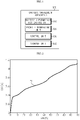
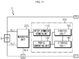
- FIG. 1 is a diagram schematically showing a battery management apparatus 100 according to an embodiment of the present disclosure.
- the battery management apparatus 100 may include a battery information estimating unit 110, a profile generating unit 120, and a control unit 130.
- the battery information estimating unit 110 may be configured to estimate battery information including OCV and SOC for a battery cell B based on at least one of voltage and current of the battery cell B.
- the battery cell B means one independent cell that includes a negative electrode terminal and a positive electrode terminal and is physically separable.
- one pouch-type lithium polymer cell may be regarded as the battery cell B.
- the OCV means an open circuit voltage
- the SOC means a state of charge
- the battery information estimating unit 110 may be configured to estimate the OCV and the SOC corresponding to each other from the voltage and the current of the battery cell B by using an equivalent circuit model (ECM) and an extended Kalman filter (EKF). Since the method of estimating OCV and SOC of a battery from voltage and current of a battery and an equivalent circuit model by using an extended Kalman filter is a known method, a detailed description thereof will be omitted.
- ECM equivalent circuit model
- EKF extended Kalman filter
- the profile generating unit 120 may be configured to receive the OCV and the SOC from the battery information estimating unit 110.
- the profile generating unit 120 and the battery information estimating unit 110 may be connected to each other to enable communication.
- the profile generating unit 120 may receive the OCV and SOC from the battery information estimating unit 110.
- the profile generating unit 120 may be configured to generate an SOC profile representing a correspondence between the OCV and the SOC.
- the SOC profile may be a profile representing the correspondence between the OCV and the SOC estimated by the battery information estimating unit 110.
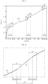
- FIG. 2 is a diagram schematically showing a SOC profile P1 generated by the battery management apparatus 100 according to an embodiment of the present disclosure.
- the SOC profile P1 is an X-Y graph where the SOC is set to X and the OCV is set to Y.
- the entire section of the SOC of the SOC profile P1 may be 0% to 100%. That is, the SOC profile P1 is a diagram showing OCV and SOC in a one-to-one relationship in the form of a flat graph.
- the control unit 130 may be configured to receive the SOC profile P1 from the profile generating unit 120.
- control unit 130 may be communicatively connected to the profile generating unit 120.
- control unit 130 may receive the SOC profile P1 from the profile generating unit 120.
- control unit 130 may be configured to determine an inflection point in the received SOC profile P1.
- the inflection point means a point at which the graph changes from an upwardly convex state to a downwardly convex state or from a downwardly convex state to an upwardly convex state in a function that is differentiable twice.
- a point at which the curvature changes from positive to negative or from positive to negative is called an inflection point.
- control unit 130 may set the SOC profile P1 representing the correspondence between the OCV and the SOC as a f(x) function, and differentiates the f(x) function twice to obtain a second derivative f"(x) of the SOC profile P1.
- the function f(x) is continuous and can be differentiated twice.
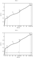
- FIG. 3 is a diagram showing an example of the inflection point included in the SOC profile P1 of FIG. 2 .
- the SOC of the first inflection point IP1 may be 10%
- the SOC of the second inflection point IP2 may be 55%
- the SOC of the third inflection point IP3 may be 95%.
- control unit 130 may be configured to set a correction section in the SOC profile P1 based on an OCV or SOC corresponding to the inflection point.
- control unit 130 may set the correction section based on the SOC.
- control unit 130 may set the correction section in the SOC profile P1 only when it is determined that an inflection point exists in the SOC profile P1. If the inflection point does not exist in the SOC profile P1, the control unit 130 does not set the correction section in the SOC profile P1, and sets the SOC profile P1 received from the profile generating unit 120 as a criterion profile for the corresponding battery cell B.
- control unit 130 may set the correction section to include the inflection point. That is, the correction section set by the control unit 130 may always include an inflection point.
- FIG. 4 is a diagram schematically showing a SOC profile P1 to which a correction section C is set by the battery management apparatus 100 according to an embodiment of the present disclosure.
- the control unit 130 may set the correction section C to include all of the first inflection point IP1, the second inflection point IP2, and the third inflection point IP3 based on the SOC.
- the correction section C may be an SOC section of 3% to 100%.
- control unit 130 may be configured to correct the SOC profile P1 by linearizing the set correction section C.
- the inflection point may appear in a non-linear section of the SOC profile P1. Accordingly, the control unit 130 may correct the SOC profile P1 by linearizing the non-linear section including the inflection point.
- control unit 130 may be configured to remove the inflection point included in the correction section C of the SOC profile P1 by applying a linearization algorithm to the correction section C.
- linearization algorithm an algorithm capable of converting a non-linear section of a curve into a linear section may be applied.
- a regression analysis method such as a least square method (LSM), a least square approximation (LSA), and a least mean square method (LMSM) may be applied.
- LSM least square method
- LSA least square approximation
- LMSM least mean square method
- FIG. 5 is a diagram schematically showing an example where the SOC profile P1 of FIG. 4 is corrected by the battery management apparatus 100 according to an embodiment of the present disclosure.
- the SOC profile P2 of FIG. 5 is an SOC profile obtained by linearizing the correction section C by the control unit 130 using the least square method. Since the correction section C including an inflection point is linearized, the corrected SOC profile P2 may not include an inflection point.
- Q means a linearized correction section C.
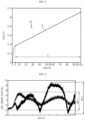
- FIG. 6 is a diagram comparatively showing a SOC error rate of the SOC profile P1 of FIG. 2 and a SOC error rate of the corrected SOC profile P2 of FIG. 5 .
- the SOC error rate means the difference in SOC for each OCV between a preset reference profile and the SOC profile for the battery cell B.
- the reference profile may be a profile preset to represent the correspondence between the OCV and SOC of the battery cell B.
- the reference profile may be a profile representing the correspondence between the OCV and the SOC for the battery cell B estimated according to a method different from the extended Kalman filter (e.g., Coulomb counting).
- the SOC error rate may be calculated according to a formula of "(SOC of SOC profile - SOC of reference profile) ⁇ SOC of reference profile ⁇ 100" for each OCV.
- the unit of the SOC error rate may be expressed as [%].
- control unit 130 may calculate the difference between the SOC for each OCV of the reference profile and the SOC for each OCV of the SOC profile (P1, P2) as an SOC error rate.
- the SOC error rate of the corrected SOC profile P2 in which the inflection point is removed by the control unit 130 may have a small variation, compared to the SOC error rate of the SOC profile P1 including the inflection point.
- the size of the error section (Perr) of the SOC profile P1 may be larger than the size of the error section (Qerr) of the corrected SOC profile P2.
- the SOC profile P2 corrected by the control unit 130 may be regarded as a more suitable profile for the battery cell B than the SOC profile P1 generated by the profile generating unit 120. That is, the SOC profile P2 corrected by the control unit 130 may be a more stable profile than the SOC profile P1 generated by the profile generating unit 120.
- the battery information estimating unit 110 estimates the SOC of the battery cell B using the extended Kalman filter
- noise may affect the Kalman gain near the inflection point included in the SOC profile P1.
- the size of the error section (Perr) of the SOC profile P1 generated by the profile generating unit 120 may be larger than the size of the error section (Qerr) of the SOC profile P2 corrected by the control unit 130. That is, the SOC profile P1 generated by the profile generating unit 120 may not be more stable than the SOC profile P2 corrected by the control unit 130 due to the influence of noise.
- the battery management apparatus 100 has an advantage of generating a more stable SOC profile P1 by correcting the SOC profile P1 of the battery cell B generated based on the extended Kalman filter using a linearization algorithm.
- control unit 130 provided to the battery management apparatus 100 may selectively include processors known in the art, application-specific integrated circuit (ASIC), other chipsets, logic circuits, registers, communication modems, data processing devices, and the like to execute various control logic performed in the present disclosure.
- ASIC application-specific integrated circuit
- the control unit 130 may be implemented as a set of program modules.
- the program module may be stored in a memory and executed by the control unit 130.
- the memory may be located inside or out of the control unit 130 and may be connected to the control unit 130 by various well-known means.
- the battery management apparatus 100 may further include a storage unit 140.
- the storage unit 140 may store data necessary for operation and function of each component of the battery management apparatus 100, data generated in the process of performing the operation or function, or the like.
- the storage unit 140 is not particularly limited in its kind as long as it is a known information storage means that can record, erase, update and read data.
- the information storage means may include RAM, flash memory, ROM, EEPROM, registers, and the like.
- the storage unit 140 may store program codes in which processes executable by the control unit 130 are defined.
- the storage unit 140 may store voltage information and current information of the battery cell B.
- the storage unit 140 may store parameters and functions related to an equivalent circuit model and an extended Kalman filter preset to correspond to the battery cell B.
- control unit 130 may be configured to set a correction section for each of the plurality of inflection points IP1, IP2, IP3.
- control unit 130 sets the correction section C including all of the first inflection point IP1, the second inflection point IP2, and the third inflection point IP3.
- control unit 130 may set a correction section for each of the first inflection point IP1, the second inflection point IP2, and the third inflection point IP3.
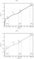
- FIG. 7 is a diagram schematically showing a SOC profile P1 to which a plurality of correction sections C1, C2, C3 are set by the battery management apparatus 100 according to an embodiment of the present disclosure.
- the control unit 130 may set a first correction section C1 for the first inflection point IP1, a second correction section C2 for the second inflection point IP2, and a third correction section C3 for the third inflection point IP3.
- the first correction section C1 may be an SOC section of 5% to 15%
- the second correction section C2 may be an SOC section of 50% to 60%
- the third correction section C3 may be an SOC section of 90% to 100%.
- control unit 130 may be configured to independently linearize each of the plurality of set correction sections C1, C2, C3.
- control unit 130 may set the correction sections C1, C2, C3 so that the inflection point does not exist in the corrected SOC profile P3.
- control unit 130 may set one correction section including all of the plurality of inflection points IP1, IP2, IP3 as in the embodiment of FIG. 3 .
- FIG. 8 is a diagram schematically showing an example where the SOC profile P1 of FIG. 7 is corrected by the battery management apparatus 100 according to an embodiment of the present disclosure.
- the control unit 130 may linearize each of the first correction section C1, the second correction section C2, and the third correction section C3.
- Q1 means a linearized first correction section C1
- Q2 means a linearized second correction section C2
- Q3 means a linearized third correction section C3. Accordingly, the first inflection point IP1, the second inflection point IP2, and the third inflection point IP3 may be removed from the corrected SOC profile P3 of FIG. 8 . That is, an inflection point may not exist in the corrected SOC profile P3.
- first inflection point IP1, the second inflection point IP2, and the third inflection point IP3 are set as middle points of the first correction section C1, the second correction section C2, and the third correction section C3, respectively, in some cases, a middle point of each of the first correction section C1, the second correction section C2, and the third correction section C3 may not be set to the first inflection point IP1, the second inflection point IP2, and the third inflection point IP3.
- section sizes of the first correction section C1, the second correction section C2, and the third correction section C3 are all set identically with an SOC of 10%
- the section sizes of the first correction section C1, the second correction section C2, and the third correction section C3 may also be set differently from each other in order to remove the plurality of inflection points IP1, IP2, IP3 included in the SOC profile P1.
- the battery management apparatus 100 may improve the SOC estimation accuracy for the battery cell B by the corrected SOC profile P3 by setting the correction sections C1, C2, C3 for each of the plurality of inflection points IP1, IP2, IP3 and independently linearizing each of the plurality of set correction sections C1, C2, C3.
- control unit 130 may be configured to set the plurality of overlapped correction sections C1, C2, C3 as one correction section.
- the first correction section C1 and the second correction section C2 are overlapped with each other.
- the first correction section C1 is set to an SOC section of 5% to 35%
- the second correction section C2 is set to an SOC section of 30% to 60%.
- the first correction section C1 and the second correction section C2 may be overlapped with each other in the SOC section of 30% to 35%.
- the control unit 130 may integrate the first correction section C1 and the second correction section C2 to set the SOC section of 5% to 60% as one correction section.
- the control unit 130 may be configured to correct the SOC profile P1 multiple times while changing the size of the correction section.
- control unit 130 may generate a plurality of corrected SOC profiles by reducing the sizes of the plurality of correction sections C1, C2, C3 by 1% SOC.
- the corrected SOC profile P3 of FIG. 8 may be any one of the plurality of corrected SOC profiles.
- the plurality of corrected SOC profiles generated by the control unit 130 may be stored in the storage unit 140.
- control unit 130 may be configured to calculate an SOC error for each of the plurality of corrected SOC profiles generated based on the preset reference profile.
- control unit 130 may calculate an SOC error rate for each of the 10 corrected SOC profiles.
- control unit 130 may be configured to calculate an SOC error rate for each OCV for each of the plurality of corrected SOC profiles by comparing the SOC for each OCV of the reference profile and the SOC for each OCV of each of the plurality of corrected SOC profiles.
- control unit 130 may be configured to select a target SOC profile having a minimum calculated SOC error rate from among the plurality of corrected SOC profiles.
- the minimum SOC error rate means that the size of the error section of the calculated SOC error rate for each OCV among the plurality of corrected SOC profiles is the minimum.
- the control unit 130 may be configured to select the corrected SOC profile P3 as the target SOC profile.
- control unit 130 may be configured to select the corrected SOC profile P3, in which the error section representing a difference between a minimum value and a maximum value of the SOC error rate for each OCV calculated for each of the plurality of corrected SOC profiles has a minimum size, as the target SOC profile.
- control unit 130 may be configured to set the selected target SOC profile as a criterion profile for the battery cell B.
- the battery management apparatus 100 may improve the accuracy of the SOC estimation, the stability of the estimation, and the reliability of the estimation for the battery cell B and the same type of secondary battery as the battery cell B based on the set criterion profile.
- the control unit 130 may be configured to set a plurality of filtering sections based on each of a start point and an end point of the correction section in the corrected SOC profile P2, P3.
- the start point of the correction section means a lowest SOC of the correction section
- the end point of the correction section means a highest SOC of the correction section.
- the start point of the first correction section C1 is an SOC of 5%
- the end point is an SOC of 15%
- the start point of the second correction section C2 is 50% SOC
- the end point is 60% SOC.
- the start point of the third correction section C3 is 90% SOC, and the end point is 100% SOC.
- FIG. 9 is a diagram schematically showing a SOC profile P3 to which a plurality of filtering sections are set by the battery management apparatus 100 according to an embodiment of the present disclosure.
- the control unit 130 may set a first filtering section F1, a second filtering section F2, a third filtering section F3, a fourth filtering section F4, and a fifth filtering section F5.
- the control unit 130 since the end point of the third correction section C3 is an SOC of 100%, the control unit 130 may not separately set a sixth filtering section F6 corresponding to the end point of the third correction section C3.
- control unit 130 may be configured to apply a filtering algorithm to each of the plurality of set filtering sections.
- the filtering algorithm may be a smoothing algorithm that may remove noise included in the correction section.
- various algorithms may be applied, and, for example, Gaussian smoothing or a low pass filter may be applied.
- the plurality of filtering sections F1, F2, F3, F4, F5 may be configured to include a linear section and a non-linear section based on the start point or the end point.
- the non-linear section may be a section existing from the SOC profile P1 generated by the profile generating unit 120
- the linear section may be sections Q, Q1, Q2, Q3 linearized by the control unit 130. The non-linear section and the linear section will be described in detail with reference to FIG. 10 .
- FIG. 10 is an enlarged view showing a part of the SOC profile P3 of FIG. 9 .
- FIG. 10 is an enlarged view exemplarily showing a part of the SOC profile P3 of FIG. 9 near the second correction section C2.
- the third filtering section F3 and the fourth filtering section F4 may include a non-linear section R_nl and a linear section R_1.
- the linear section R_1 may mean a linearized second correction section C2. That is, since the filtering section includes the start point or the end point of the correction section, both the non-linear section R_nl and the linear section R_1 may be included in the filtering section.
- control unit 130 may be configured to correct each of the plurality of filtering sections F1, F2, F3, F4, F5 using the filtering algorithm so that the linear section R_1 and the non-linear section R_nl become continuous sections.
- the least square method is used as the linearization algorithm.
- the linear section R_1 and the non-linear section R_nl included in the second correction section C2 may not be continuous with each other. That is, the linear section R_1 may not be continuous with the non-linear section R_nl because the least square method is a regression analysis method for approximately deriving an equation in which the sum of the squares of residuals of a plurality of data is minimized.
- control unit 130 may correct SOC profile P3 so that the non-linear section R_nl and the linear section R_1 become continuous sections by setting the filtering sections F3, F4 for each of the start point and the end point of the correction section C2 and applying the filtering algorithm to each of the set filtering sections F3, F4.
- the battery management apparatus 100 may primarily correct the SOC profile P1 by applying a linearization algorithm to the correction section set to include an inflection point and secondarily correct the SOC profile P3 by applying a filtering algorithm to a partial section (filtering section) of the primarily corrected SOC profile P3. That is, the SOC profile P3 corrected by the battery management apparatus 100 may more accurately represent the correspondence between the OCV and the SOC for the battery cell B than the SOC profile P1 generated using the extended Kalman filter. Accordingly, according to the SOC profile P3 corrected by the battery management apparatus 100, the accuracy and reliability of the SOC estimation for the battery cell B may be improved.
- the battery management apparatus 100 may be applied to a BMS (Battery Management System). That is, the BMS according to the present disclosure may include the battery management apparatus 100 described above. In this configuration, at least some of components of the battery management apparatus 100 may be implemented by supplementing or adding functions of components included in a conventional BMS. For example, the battery information estimating unit 110, the profile generating unit 120, the control unit 130, and the storage unit 140 of the battery management apparatus 100 may be implemented as components of the BMS. In addition, the BMS may use the SOC profile corrected by the control unit 130 to estimate the SOC of the battery cell B.
- BMS Battery Management System
- the battery management apparatus 100 may be provided to a battery pack 1. That is, the battery pack 1 according to the present disclosure may include the battery management apparatus 100 described above and at least one battery cell B. In addition, the battery pack 1 may further include electrical equipment (relays, fuses, etc.) and a case.
- FIG. 11 is a diagram schematically showing an exemplary configuration of a battery pack 1 including the battery management apparatus 100 according to an embodiment of the present disclosure.
- the battery pack 1 may include a battery cell B, a measuring unit 200, and a battery management apparatus 100.
- the measuring unit 200 may be configured to measure the voltage and current of the battery cell B.
- the measuring unit 200 may measure the voltage of the battery through a first sensing line SL1 and a second sensing line SL2.
- the measuring unit 200 may measure the current of the battery through a third sensing line SL3 connected to a current measuring unit A.
- the measuring unit 200 may be connected to communicate with the battery information estimating unit 110 of the battery management apparatus 100. Accordingly, when the measuring unit 200 outputs the measured voltage information and current information of the battery cell B, the battery information estimating unit 110 may receive the voltage information and the current information of the battery cell B from the measuring unit 200.
- a load capable of charging or discharging the battery cell B may be further connected to a positive electrode terminal (P+) and a negative electrode terminal (P-) of the battery pack 1.
- the battery management apparatus 100 may be included in a battery manufacturing system.
- the battery manufacturing system may mean a system that can be applied to the process of producing, assembling and inspecting a battery cell B.
- the battery management apparatus 100 may be used to obtain the corrected SOC profile P2, P3 for the produced battery cell B in the process of inspecting the battery cell B. That is, the SOC profile P2, P3 corrected by the battery management apparatus 100 may be set as a criterion profile for the corresponding battery cell B. Thereafter, the SOC of the corresponding battery cell B may be estimated based on the criterion profile set by the battery management apparatus 100.
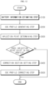
- FIG. 12 is a diagram schematically showing a battery management method according to another embodiment of the present disclosure.
- Each step of the battery management method may be performed by the battery management apparatus 100.
- the battery management apparatus 100 may perform various steps.
- content overlapping with the previously described content will be briefly described or omitted.
- the battery management method may include a battery information estimating step (S100), a SOC profile generating step (S200), an inflection point determining step (S300), a correction section setting step (S400), and a SOC profile correcting step (S500).
- S100 battery information estimating step
- S200 SOC profile generating step
- S300 SOC profile generating step
- S400 correction section setting step
- S500 SOC profile correcting step
- the battery information estimating step (S100) is a step of estimating battery information including OCV and SOC for the battery cell B based on at least one of voltage and current of the battery cell B, and may be performed by the battery information estimating unit 110.
- the battery information estimating unit 110 may estimate OCV and SOC for the battery cell B using the voltage and the current of the battery cell B, and a preset equivalent circuit model and extended Kalman filter.
- the SOC profile generating step (S200) is a step of generating a SOC profile P1 representing a correspondence between the OCV and the SOC estimated in the battery information estimating step (S100), and may be performed by the profile generating unit 120.
- the profile generating unit 120 may generate the SOC profile P1.
- the inflection point determining step (S300) is a step of determining an inflection point in the SOC profile P1, and may be performed by the control unit 130.
- control unit 130 may determine a first inflection point IP1, a second inflection point IP2, and a third inflection point IP3 in the SOC profile P1.
- the correction section setting step (S400) and the SOC profile correcting step (S500) may be performed when at least one inflection point exists in the SOC profile P1. If an inflection point does not exist in the SOC profile P1 generated in the SOC profile generating step (S200), the correction section setting step (S400) and the SOC profile correcting step (S500) may not be performed.
- the correction section setting step (S400) is a step of setting a correction section C in the SOC profile P1 based on the OCV or SOC corresponding to the inflection point, and may be performed by the control unit 130.
- the control unit 130 may set the correction section C to include the inflection points IP1, IP2, IP3 of the SOC profile P1. Specifically, when the correction section is corrected in the SOC profile correcting step (S500), the control unit 130 may set the correction section so that an inflection point does not exist in the corrected SOC profile.
- the SOC profile correcting step (S500) is a step of correcting the SOC profile P1 by linearizing the correction section set in the correction section setting step (S400), and may be performed by the control unit 130.
- control unit 130 may remove the inflection points IP1, IP2, IP3 included in the correction section C by linearizing the correction section C. Therefore, since an inflection point does not exist in the corrected SOC profile P2, an SOC error rate of the corrected SOC profile P2 may be smaller than an SOC error rate of the SOC profile P1 generated in the SOC profile generating step (S200).
- control unit 130 may set the corrected SOC profile P2 as a criterion profile for the battery cell B.
- the battery management method has an advantage of setting a more suitable criterion profile for the battery cell B by correcting the SOC profile P1 generated using the extended Kalman filter.
- the embodiments of the present disclosure described above may not be implemented only through an apparatus and a method, but may be implemented through a program that realizes a function corresponding to the configuration of the embodiments of the present disclosure or a recording medium on which the program is recorded.
- the program or recording medium may be easily implemented by those skilled in the art from the above description of the embodiments.
Landscapes
- Physics & Mathematics (AREA)
- General Physics & Mathematics (AREA)
- Engineering & Computer Science (AREA)
- Manufacturing & Machinery (AREA)
- Chemical & Material Sciences (AREA)
- Chemical Kinetics & Catalysis (AREA)
- Electrochemistry (AREA)
- General Chemical & Material Sciences (AREA)
- Secondary Cells (AREA)
- Charge And Discharge Circuits For Batteries Or The Like (AREA)
- Tests Of Electric Status Of Batteries (AREA)
Applications Claiming Priority (2)
| Application Number | Priority Date | Filing Date | Title |
|---|---|---|---|
| KR1020200101933A KR102851926B1 (ko) | 2020-08-13 | 2020-08-13 | 배터리 관리 장치 및 방법 |
| PCT/KR2021/010342 WO2022035130A1 (fr) | 2020-08-13 | 2021-08-05 | Dispositif et procédé de gestion de batterie |
Publications (2)
| Publication Number | Publication Date |
|---|---|
| EP4148441A1 true EP4148441A1 (fr) | 2023-03-15 |
| EP4148441A4 EP4148441A4 (fr) | 2023-11-22 |
Family
ID=80246769
Family Applications (1)
| Application Number | Title | Priority Date | Filing Date |
|---|---|---|---|
| EP21856136.3A Pending EP4148441A4 (fr) | 2020-08-13 | 2021-08-05 | Dispositif et procédé de gestion de batterie |
Country Status (6)
| Country | Link |
|---|---|
| US (1) | US20230176130A1 (fr) |
| EP (1) | EP4148441A4 (fr) |
| JP (1) | JP7351024B2 (fr) |
| KR (1) | KR102851926B1 (fr) |
| CN (1) | CN115461636B (fr) |
| WO (1) | WO2022035130A1 (fr) |
Cited By (3)
| Publication number | Priority date | Publication date | Assignee | Title |
|---|---|---|---|---|
| EP4468004A4 (fr) * | 2022-12-28 | 2025-06-25 | LG Energy Solution, Ltd. | Appareil et procédé de gestion de batterie |
| EP4628915A4 (fr) * | 2022-12-26 | 2026-03-04 | Lg Energy Solution Ltd | Appareil et procédé de gestion de batterie |
| EP4553523A4 (fr) * | 2022-12-26 | 2026-03-04 | Lg Energy Solution Ltd | Appareil et procédé de gestion de batterie |
Families Citing this family (13)
| Publication number | Priority date | Publication date | Assignee | Title |
|---|---|---|---|---|
| KR102620174B1 (ko) | 2022-09-02 | 2024-01-02 | 주식회사 엘지에너지솔루션 | 배터리 진단 장치, 배터리 검사 시스템 및 배터리 진단 방법 |
| KR102887071B1 (ko) * | 2022-12-26 | 2025-11-17 | 주식회사 엘지에너지솔루션 | 배터리 관리 장치 및 방법 |
| KR102886560B1 (ko) * | 2022-12-26 | 2025-11-14 | 주식회사 엘지에너지솔루션 | 배터리 관리 장치 및 방법 |
| KR102917280B1 (ko) * | 2023-03-06 | 2026-01-23 | 주식회사 엘지에너지솔루션 | 배터리 데이터 관리 장치 및 그것의 동작 방법 |
| CN120731379A (zh) * | 2023-08-31 | 2025-09-30 | 株式会社Lg新能源 | 用于估计soh的装置和方法 |
| KR102836737B1 (ko) * | 2023-08-31 | 2025-07-18 | 주식회사 엘지에너지솔루션 | 배터리 진단 장치 및 방법 |
| CN121013993A (zh) * | 2023-08-31 | 2025-11-25 | 株式会社Lg新能源 | 用于估计soh的装置和方法 |
| WO2025048463A1 (fr) * | 2023-08-31 | 2025-03-06 | 주식회사 엘지에너지솔루션 | Appareil et procédé d'estimation de soh |
| KR102892184B1 (ko) * | 2023-12-26 | 2025-12-01 | 주식회사 엘지에너지솔루션 | 배터리 진단 장치, 배터리 팩, 배터리 시스템 및 배터리 진단 방법 |
| KR20250150291A (ko) * | 2024-04-11 | 2025-10-20 | 주식회사 엘지에너지솔루션 | 배터리 프로파일 생성 장치 및 방법 |
| CN118818308B (zh) * | 2024-06-06 | 2026-04-24 | 联合汽车电子有限公司 | 一种电池荷电状态自适应估计方法及装置、一种车辆 |
| KR20260034902A (ko) * | 2024-09-05 | 2026-03-12 | 주식회사 엘지에너지솔루션 | 배터리 진단 장치 및 그 방법 |
| CN121432220B (zh) * | 2025-12-31 | 2026-04-10 | 杭州科工电子科技股份有限公司 | 一种钠离子电池分阶段soc校准方法及系统 |
Family Cites Families (25)
| Publication number | Priority date | Publication date | Assignee | Title |
|---|---|---|---|---|
| JP3740323B2 (ja) | 1998-07-31 | 2006-02-01 | キヤノン株式会社 | 二次電池の充電方法及びその装置 |
| KR100766982B1 (ko) | 2006-09-05 | 2007-10-15 | 삼성에스디아이 주식회사 | 배터리 관리 시스템 및 그의 구동 방법 |
| KR100805116B1 (ko) | 2006-09-08 | 2008-02-21 | 삼성에스디아이 주식회사 | 배터리 관리 시스템 및 그 구동방법 |
| KR101238478B1 (ko) * | 2011-01-16 | 2013-03-04 | 김득수 | 배터리 잔존 용량 측정 방법 |
| KR101493355B1 (ko) * | 2011-12-26 | 2015-02-13 | 주식회사 케이티 | 에너지 저장 장치의 soc 보정 방법 및 이를 이용하는 soc 보정 시스템 |
| JP5794933B2 (ja) * | 2012-02-29 | 2015-10-14 | 三菱重工業株式会社 | 充電率演算システムおよび充電率演算方法 |
| US10101401B2 (en) * | 2015-03-05 | 2018-10-16 | Gs Yuasa International Ltd. | Energy storage device management apparatus, energy storage device management method, energy storage device module, energy storage device management program, and movable body |
| KR20180049590A (ko) * | 2016-11-03 | 2018-05-11 | 한국전기연구원 | 이차전지의 soc-ocv 데이터 수집장치, 수집방법 및 이차전지의 모델링 장치 |
| KR102016715B1 (ko) * | 2016-11-23 | 2019-10-21 | 한국전기연구원 | 배터리 상태 추정 방법, 그 방법을 수행하는 장치 및 컴퓨터 프로그램 |
| KR102066702B1 (ko) * | 2017-01-02 | 2020-03-02 | 주식회사 엘지화학 | 배터리 관리 장치 및 이를 이용한 soc 캘리브레이션 방법 |
| WO2019003377A1 (fr) * | 2017-06-29 | 2019-01-03 | 株式会社東芝 | Dispositif d'estimation de quantité restante de batterie d'accumulateurs, procédé d'estimation de quantité restante de batterie d'accumulateurs et programme |
| KR102683336B1 (ko) * | 2017-10-11 | 2024-07-09 | 주식회사 엘지에너지솔루션 | 배터리의 용량 추정 장치 및 방법, 이를 구비하는 배터리 관리 장치 및 방법 |
| JP6988386B2 (ja) * | 2017-11-08 | 2022-01-05 | 株式会社Gsユアサ | 蓄電素子の管理装置、及び、管理方法 |
| KR102206606B1 (ko) * | 2017-11-16 | 2021-01-21 | 주식회사 엘지화학 | 배터리 여유 용량 추정 장치 |
| JP7236806B2 (ja) | 2018-01-09 | 2023-03-10 | スリーエム イノベイティブ プロパティズ カンパニー | フィルター、金属イオンの除去方法及び金属イオン除去装置 |
| CN108398647B (zh) * | 2018-03-01 | 2020-07-24 | 杭州高特新能源技术有限公司 | 锂电池不同充放电曲线获取方法 |
| KR102013306B1 (ko) * | 2018-05-11 | 2019-08-22 | 울산대학교 산학협력단 | 배터리 수명 예측방법 |
| KR102688034B1 (ko) * | 2018-08-30 | 2024-07-23 | 주식회사 엘지에너지솔루션 | 이차 전지의 충전 시간 추정 장치 및 방법 |
| KR102439598B1 (ko) * | 2018-10-25 | 2022-09-05 | 주식회사 엘지에너지솔루션 | 이차 전지의 내부 가스 발생 가속 구간 판단 방법 |
| KR102392399B1 (ko) * | 2018-12-21 | 2022-04-28 | 주식회사 엘지에너지솔루션 | 이차 전지의 스텝 충전 제어 장치 및 방법 |
| CN113075555B (zh) * | 2019-05-24 | 2024-08-23 | 宁德时代新能源科技股份有限公司 | Soc修正方法和装置、电池管理系统和存储介质 |
| CN111308371A (zh) * | 2019-11-29 | 2020-06-19 | 湖南海博瑞德电智控制技术有限公司 | 一种锂离子的电池荷电状态估算方法 |
| CN110931901B (zh) | 2019-12-13 | 2021-04-06 | 重庆理工大学 | 模拟铅酸电池电气特性的锂电池柔性集成方法与系统 |
| CN111208439B (zh) * | 2020-01-19 | 2021-10-22 | 中国科学技术大学 | 一种串联锂离子电池组微短路故障定量检测方法 |
| CN112130084A (zh) * | 2020-08-18 | 2020-12-25 | 桑顿新能源科技(长沙)有限公司 | 一种基于充电末端估计电池soc方法和系统 |
-
2020
- 2020-08-13 KR KR1020200101933A patent/KR102851926B1/ko active Active
-
2021
- 2021-08-05 WO PCT/KR2021/010342 patent/WO2022035130A1/fr not_active Ceased
- 2021-08-05 US US17/919,419 patent/US20230176130A1/en active Pending
- 2021-08-05 EP EP21856136.3A patent/EP4148441A4/fr active Pending
- 2021-08-05 JP JP2022566236A patent/JP7351024B2/ja active Active
- 2021-08-05 CN CN202180028986.1A patent/CN115461636B/zh active Active
Cited By (3)
| Publication number | Priority date | Publication date | Assignee | Title |
|---|---|---|---|---|
| EP4628915A4 (fr) * | 2022-12-26 | 2026-03-04 | Lg Energy Solution Ltd | Appareil et procédé de gestion de batterie |
| EP4553523A4 (fr) * | 2022-12-26 | 2026-03-04 | Lg Energy Solution Ltd | Appareil et procédé de gestion de batterie |
| EP4468004A4 (fr) * | 2022-12-28 | 2025-06-25 | LG Energy Solution, Ltd. | Appareil et procédé de gestion de batterie |
Also Published As
| Publication number | Publication date |
|---|---|
| EP4148441A4 (fr) | 2023-11-22 |
| US20230176130A1 (en) | 2023-06-08 |
| CN115461636A (zh) | 2022-12-09 |
| JP2023523803A (ja) | 2023-06-07 |
| JP7351024B2 (ja) | 2023-09-26 |
| WO2022035130A1 (fr) | 2022-02-17 |
| KR102851926B1 (ko) | 2025-08-27 |
| KR20220021276A (ko) | 2022-02-22 |
| CN115461636B (zh) | 2025-11-04 |
Similar Documents
| Publication | Publication Date | Title |
|---|---|---|
| EP4148441A1 (fr) | Dispositif et procédé de gestion de batterie | |
| EP4131571B1 (fr) | Dispositif et procédé de gestion de batterie | |
| CN115516695B (zh) | 电池管理装置、电池组及电池管理方法 | |
| US10663524B2 (en) | Battery state estimating apparatus | |
| KR20200102923A (ko) | 배터리 상태 추정 장치 및 방법 | |
| EP3637120B1 (fr) | Appareil et procédé d'estimation de l'état de charge (soc) d'une batterie | |
| EP3828565A1 (fr) | Véhicule et son procédé de commande | |
| CN115667957B (zh) | 电池管理设备、电池检测装置及电池管理方法 | |
| Vishnu et al. | Adaptive integral correction-based state of charge estimation strategy for lithium-ion cells | |
| EP4462140B1 (fr) | Appareil et procédé pour estimer des paramètres d'une batterie | |
| EP4318005B1 (fr) | Appareil et procédé d'évaluation d'état de batterie | |
| Lopetegi et al. | Electrode State of Charge and State of Health Estimation with Electrode-Level Equivalent-Circuit Models | |
| US12620641B2 (en) | Battery management apparatus and method | |
| US20260110752A1 (en) | Battery SOH Estimating Apparatus and Method | |
| EP4571336A1 (fr) | Appareil et procédé d'estimation de soh de batterie | |
| US20250237706A1 (en) | Battery diagnostic device and method | |
| CN120731379A (zh) | 用于估计soh的装置和方法 | |
| CN120660011A (zh) | 用于估计soh的装置和方法 | |
| CN120641772A (zh) | 用于估计soh的装置和方法 |
Legal Events
| Date | Code | Title | Description |
|---|---|---|---|
| STAA | Information on the status of an ep patent application or granted ep patent |
Free format text: STATUS: THE INTERNATIONAL PUBLICATION HAS BEEN MADE |
|
| PUAI | Public reference made under article 153(3) epc to a published international application that has entered the european phase |
Free format text: ORIGINAL CODE: 0009012 |
|
| STAA | Information on the status of an ep patent application or granted ep patent |
Free format text: STATUS: REQUEST FOR EXAMINATION WAS MADE |
|
| 17P | Request for examination filed |
Effective date: 20221208 |
|
| AK | Designated contracting states |
Kind code of ref document: A1 Designated state(s): AL AT BE BG CH CY CZ DE DK EE ES FI FR GB GR HR HU IE IS IT LI LT LU LV MC MK MT NL NO PL PT RO RS SE SI SK SM TR |
|
| A4 | Supplementary search report drawn up and despatched |
Effective date: 20231020 |
|
| DAV | Request for validation of the european patent (deleted) | ||
| DAX | Request for extension of the european patent (deleted) | ||
| RIC1 | Information provided on ipc code assigned before grant |
Ipc: G01R 31/382 20190101ALI20231016BHEP Ipc: G01R 31/374 20190101ALI20231016BHEP Ipc: G01R 31/36 20200101ALI20231016BHEP Ipc: G01R 31/367 20190101AFI20231016BHEP |
|
| STAA | Information on the status of an ep patent application or granted ep patent |
Free format text: STATUS: EXAMINATION IS IN PROGRESS |
|
| 17Q | First examination report despatched |
Effective date: 20251006 |