EP4149191A1 - Verfahren und vorrichtung zur zeitbestimmung, endgerät und netzwerkvorrichtung - Google Patents
Verfahren und vorrichtung zur zeitbestimmung, endgerät und netzwerkvorrichtung Download PDFInfo
- Publication number
- EP4149191A1 EP4149191A1 EP21803758.8A EP21803758A EP4149191A1 EP 4149191 A1 EP4149191 A1 EP 4149191A1 EP 21803758 A EP21803758 A EP 21803758A EP 4149191 A1 EP4149191 A1 EP 4149191A1
- Authority
- EP
- European Patent Office
- Prior art keywords
- time
- pdcch
- pdcch monitoring
- monitoring occasion
- inactivity timer
- Prior art date
- Legal status (The legal status is an assumption and is not a legal conclusion. Google has not performed a legal analysis and makes no representation as to the accuracy of the status listed.)
- Granted
Links
Images


Classifications
-
- H—ELECTRICITY
- H04—ELECTRIC COMMUNICATION TECHNIQUE
- H04L—TRANSMISSION OF DIGITAL INFORMATION, e.g. TELEGRAPHIC COMMUNICATION
- H04L5/00—Arrangements affording multiple use of the transmission path
- H04L5/003—Arrangements for allocating sub-channels of the transmission path
- H04L5/0048—Allocation of pilot signals, i.e. of signals known to the receiver
- H04L5/0051—Allocation of pilot signals, i.e. of signals known to the receiver of dedicated pilots, i.e. pilots destined for a single user or terminal
-
- H—ELECTRICITY
- H04—ELECTRIC COMMUNICATION TECHNIQUE
- H04W—WIRELESS COMMUNICATION NETWORKS
- H04W72/00—Local resource management
- H04W72/20—Control channels or signalling for resource management
- H04W72/23—Control channels or signalling for resource management in the downlink direction of a wireless link, i.e. towards a terminal
-
- H—ELECTRICITY
- H04—ELECTRIC COMMUNICATION TECHNIQUE
- H04L—TRANSMISSION OF DIGITAL INFORMATION, e.g. TELEGRAPHIC COMMUNICATION
- H04L5/00—Arrangements affording multiple use of the transmission path
- H04L5/0001—Arrangements for dividing the transmission path
- H04L5/0003—Two-dimensional division
- H04L5/0005—Time-frequency
- H04L5/0007—Time-frequency the frequencies being orthogonal, e.g. OFDM(A) or DMT
- H04L5/001—Time-frequency the frequencies being orthogonal, e.g. OFDM(A) or DMT the frequencies being arranged in component carriers
-
- H—ELECTRICITY
- H04—ELECTRIC COMMUNICATION TECHNIQUE
- H04L—TRANSMISSION OF DIGITAL INFORMATION, e.g. TELEGRAPHIC COMMUNICATION
- H04L5/00—Arrangements affording multiple use of the transmission path
- H04L5/003—Arrangements for allocating sub-channels of the transmission path
- H04L5/0053—Allocation of signalling, i.e. of overhead other than pilot signals
-
- H—ELECTRICITY
- H04—ELECTRIC COMMUNICATION TECHNIQUE
- H04L—TRANSMISSION OF DIGITAL INFORMATION, e.g. TELEGRAPHIC COMMUNICATION
- H04L5/00—Arrangements affording multiple use of the transmission path
- H04L5/003—Arrangements for allocating sub-channels of the transmission path
- H04L5/0078—Timing of allocation
-
- H—ELECTRICITY
- H04—ELECTRIC COMMUNICATION TECHNIQUE
- H04W—WIRELESS COMMUNICATION NETWORKS
- H04W68/00—User notification, e.g. alerting and paging, for incoming communication, change of service or the like
- H04W68/02—Arrangements for increasing efficiency of notification or paging channel
-
- H—ELECTRICITY
- H04—ELECTRIC COMMUNICATION TECHNIQUE
- H04W—WIRELESS COMMUNICATION NETWORKS
- H04W72/00—Local resource management
- H04W72/04—Wireless resource allocation
- H04W72/044—Wireless resource allocation based on the type of the allocated resource
- H04W72/0446—Resources in time domain, e.g. slots or frames
-
- H—ELECTRICITY
- H04—ELECTRIC COMMUNICATION TECHNIQUE
- H04W—WIRELESS COMMUNICATION NETWORKS
- H04W72/00—Local resource management
- H04W72/04—Wireless resource allocation
- H04W72/044—Wireless resource allocation based on the type of the allocated resource
- H04W72/0457—Variable allocation of band or rate
-
- H—ELECTRICITY
- H04—ELECTRIC COMMUNICATION TECHNIQUE
- H04W—WIRELESS COMMUNICATION NETWORKS
- H04W72/00—Local resource management
- H04W72/20—Control channels or signalling for resource management
- H04W72/23—Control channels or signalling for resource management in the downlink direction of a wireless link, i.e. towards a terminal
- H04W72/232—Control channels or signalling for resource management in the downlink direction of a wireless link, i.e. towards a terminal the control data signalling from the physical layer, e.g. DCI signalling
-
- H—ELECTRICITY
- H04—ELECTRIC COMMUNICATION TECHNIQUE
- H04W—WIRELESS COMMUNICATION NETWORKS
- H04W76/00—Connection management
- H04W76/20—Manipulation of established connections
- H04W76/28—Discontinuous transmission [DTX]; Discontinuous reception [DRX]
-
- H—ELECTRICITY
- H04—ELECTRIC COMMUNICATION TECHNIQUE
- H04L—TRANSMISSION OF DIGITAL INFORMATION, e.g. TELEGRAPHIC COMMUNICATION
- H04L1/00—Arrangements for detecting or preventing errors in the information received
- H04L1/08—Arrangements for detecting or preventing errors in the information received by repeating transmission, e.g. Verdan system
-
- H—ELECTRICITY
- H04—ELECTRIC COMMUNICATION TECHNIQUE
- H04L—TRANSMISSION OF DIGITAL INFORMATION, e.g. TELEGRAPHIC COMMUNICATION
- H04L5/00—Arrangements affording multiple use of the transmission path
- H04L5/0001—Arrangements for dividing the transmission path
- H04L5/0003—Two-dimensional division
- H04L5/0005—Time-frequency
-
- H—ELECTRICITY
- H04—ELECTRIC COMMUNICATION TECHNIQUE
- H04L—TRANSMISSION OF DIGITAL INFORMATION, e.g. TELEGRAPHIC COMMUNICATION
- H04L5/00—Arrangements affording multiple use of the transmission path
- H04L5/0091—Signalling for the administration of the divided path, e.g. signalling of configuration information
- H04L5/0096—Indication of changes in allocation
- H04L5/0098—Signalling of the activation or deactivation of component carriers, subcarriers or frequency bands
-
- H—ELECTRICITY
- H04—ELECTRIC COMMUNICATION TECHNIQUE
- H04W—WIRELESS COMMUNICATION NETWORKS
- H04W68/00—User notification, e.g. alerting and paging, for incoming communication, change of service or the like
- H04W68/005—Transmission of information for alerting of incoming communication
Definitions
- This application relates to the field of communications technologies, and in particular, to a time determining method and apparatus, a terminal, and a network device.
- the network side may indicate some control information to terminals by using physical downlink control channel (Physical downlink control channel, PDCCH), and the terminal may perform a corresponding behavior according to such control information, for example, starting or restarting an inactivity timer, bandwidth part (Bandwidth part, BWP) switching, uplink transmission or downlink reception, or the like.
- PDCCH Physical downlink control channel
- BWP bandwidth part
- terminals all determine, based on a time of a PDCCH monitoring occasion (monitoring occasion, MO) on which a PDCCH is detected, a start time of a behavior corresponding to the PDCCH.
- the inventors have found that the network side may not be able to accurately know on which PDCCH monitoring occasion the terminal has detected the PDCCH, and as a result, the network side and the terminal have inconsistent understanding on the start time of the behavior corresponding to the PDCCH, affecting transmission performance between the terminal and the network side.
- This application provides a time determining method and apparatus, a terminal, and a network device, so as to resolve a problem that a network side and a terminal have inconsistent understanding on a start time of a behavior corresponding to a PDCCH, thereby affecting transmission performance between the terminal and the network side.
- an embodiment of this application provides a time determining method, applied to a terminal and including:
- the plurality of PDCCH monitoring occasions are monitoring occasions for performing repetition transmission of the first PDCCH; or information indicated by a plurality of PDCCHs is at least partially the same, where the plurality of PDCCHs are PDCCHs transmitted on the plurality of PDCCH monitoring occasions.
- an embodiment of this application provides a time determining method, applied to a network device and including:
- an embodiment of this application provides a time determining apparatus, applied to a terminal and including:
- an embodiment of this application provides a time determining apparatus, applied to a network device and including:
- an embodiment of this application provides a terminal, including a memory, a processor, and a program or an instruction stored in the memory and capable of running on the processor, where when the program or the instruction is executed by the processor, the steps of the time determining method on the terminal side provided in the embodiments of this application are implemented.
- an embodiment of this application provides a network device, including a memory, a processor, and a program or an instruction stored in the memory and capable of running on the processor, where when the program or the instruction is executed by the processor, the steps of the time determining method on the network device side provided in the embodiments of this application are implemented.
- an embodiment of this application provides a readable storage medium, where the readable storage medium stores a program or an instruction, and when the program or instruction is executed by a processor, the steps of the time determining method on the terminal side provided in the embodiments of this application are implemented; or when the program or instruction is executed by a processor, the steps of the time determining method on the network device side provided in the embodiments of this application are implemented.
- an embodiment of this application provides a chip, including a processor and a communications interface, where the communications interface is coupled to the processor, and the processor is configured to run a program or an instruction to implement the steps of the time determining method on the terminal side provided in the embodiments of this application or the steps of the time determining method on the network device side provided in the embodiments of this application.
- an embodiment of this application provides a computer program product, where the program product is stored in a non-volatile storage medium, and the program product is executed by at least one processor to implement the steps of the time determining method on the terminal side provided in the embodiments of this application or the steps of the time determining method on the network device side provided in the embodiments of this application.
- monitoring is performed on the first physical downlink control channel PDCCH monitoring occasion in the plurality of PDCCH monitoring occasions, so as to detect the first PDCCH; and the start time of the first behavior corresponding to the first PDCCH is determined based on the time of the reference PDCCH monitoring occasion in the plurality of PDCCH monitoring occasions.
- the plurality of PDCCH monitoring occasions are monitoring occasions for performing repetition transmission of the first PDCCH; or the information indicated by a plurality of PDCCHs is at least partially the same, where the plurality of PDCCHs are PDCCHs transmitted on the plurality of PDCCH monitoring occasions.
- the start time of the first behavior corresponding to the first PDCCH can be determined based on the time of the reference PDCCH monitoring occasion in the plurality of PDCCH monitoring occasions, so that the network side and the terminal have consistent understanding on the start time of the behavior corresponding to the PDCCH, thereby improving transmission performance between the terminal and the network side.
- an example or “for example” are used to represent an example, an illustration, or a description. Any embodiment or design scheme described as “an example” or “for example” in the embodiments of this application should not be construed as being more preferred or advantageous than other embodiments or design schemes. To be precise, the words such as “an example” or “for example” are intended to present a related concept in a specific manner.
- the determining method and apparatus, terminal, and network device provided in the embodiments of this application can be applied to a wireless communications system.
- the wireless communications system may be a new radio (New Radio, NR) system, or other systems, such as an evolved long term evolution (Evolved Long Term Evolution, eLTE) system, a long term evolution (Long Term Evolution, LTE) system, or a later evolved communications system, further, may be applied to an unlicensed band (Unlicensed Band) in the wireless communications system.
- New Radio, NR New Radio
- NR New Radio
- eLTE evolved long term evolution
- LTE Long Term Evolution
- LTE Long Term Evolution
- later evolved communications system further, may be applied to an unlicensed band (Unlicensed Band) in the wireless communications system.
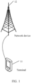
- FIG. 1 is a structural diagram of a network system to which the embodiments of this application are applicable.
- the network system includes a terminal 11 and a network device 12.
- the terminal 11 may be a user terminal (User Equipment, UE) or another terminal-side device, for example, terminal-side devices such as a mobile phone, a tablet personal computer (Tablet Personal Computer), a laptop computer (Laptop Computer), a personal digital assistant (personal digital assistant, PDA), a mobile Internet device (Mobile Internet Device, MID), or a wearable device (Wearable Device).
- UE User Equipment
- PDA personal digital assistant
- a mobile Internet device Mobile Internet Device, MID
- Wearable Device wearable Device
- the network device 12 may be a 4G base station, a 5G base station, or a base station of a later version, or a base station in another communications system, or is referred to as a NodeB, or an evolved NodeB, or a transmission reception point (Transmission Reception Point, TRP), or an access point (Access Point, AP), or other terms in the art. As long as a same technical effect is achieved, the network device is not limited to a specific technical term.
- the network device 12 may be a master node (Master Node, MN) or a secondary node (Secondary Node, SN).
- the 5G base station is used merely as an example in this embodiment of this application, rather than limiting a specific type of the network device.
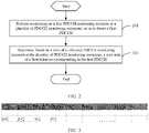
- FIG. 2 is a flowchart of a time determining method according to an embodiment of this application. The method is applied to a terminal, and as shown in FIG. 2 , includes the following steps.
- Step 201 Perform monitoring on a first PDCCH monitoring occasion in a plurality of PDCCH monitoring occasions, so as to detect a first PDCCH.
- the plurality of PDCCH monitoring occasions are monitoring occasions for performing repetition transmission of the first PDCCH; or information indicated by a plurality of PDCCHs is at least partially the same, where the plurality of PDCCHs are PDCCHs transmitted on the plurality of PDCCH monitoring occasions.
- one PDCCH may be understood as one PDCCH signal or one PDCCH message.
- the plurality of PDCCH monitoring occasions being monitoring occasions for performing repetition transmission of the first PDCCH may be that the plurality of PDCCH monitoring occasions is used for repetition transmission of the first PDCCH, that is, the network device performs repetition transmission of the first PDCCH on the plurality of PDCCH monitoring occasions.
- Information indicated by the plurality of PDCCHs being at least partially the same may be that part or all of the information indicated by the plurality of PDCCHs may be the same.
- scheduling information of the plurality of PDCCHs indicates same scheduling content, for example, the plurality of PDCCHs schedule a same physical downlink shared channel (Physical downlink shared channel, PDSCH) for transmission, or schedules the terminal to transmit data on a same resource.
- the plurality of PDCCH monitoring occasions are in different slots (slot).
- PDCCHs transmitted on the plurality of PDCCH monitoring occasions all schedule the terminal to transmit data in a first slot, which may be specifically that values of scheduling offset indications (such as k0 or k2) of the PDCCHs transmitted on the plurality of PDCCH monitoring occasions are different.
- the scheduling information of the plurality of PDCCHs may be the same while the other indication information may be the same or different.
- this embodiment of this application is not limited to the scheduling information being the same, for example, may be a switching indication, a timing indication, or an activation indication being the same.
- the PDCCHs transmitted on the plurality of PDCCH monitoring occasions do not necessarily mean that the information indicated by the plurality of PDCCHs is exactly the same. It is acceptable that only part of the information is the same, or different information bits are sent and correspond to same indication information. For example, specific values of time offset information (kO) and time offset information (k2) indicated by the PDCCHs in different slots may be different, but correspond to a same resource for actual PDSCH or PUSCH transmission, where the time offset information (kO) is a time offset between a PDCCH and a scheduled PDSCH, and the time offset information (k2) is a time offset between a PDCCH and a scheduled PUSCH.
- time offset information (kO) is a time offset between a PDCCH and a scheduled PDSCH
- time offset information (k2) is a time offset between a PDCCH and a scheduled PUSCH.
- scheduling the PDSCH in the manner of PDCCH repetition can also be expressed as transmitting a plurality of PDCCHs to schedule same PDSCH transmission.
- the PDSCH transmission may be non-repeated PDSCH transmission or repeated PDSCH transmission, where redundancy versions (Redundancy Version, RV) of a plurality of PDSCHs for repeated transmission may be the same or different.
- RV Redundancy Version
- the first PDCCH monitoring occasion may be any PDCCH monitoring occasion in the plurality of PDCCH monitoring occasions, such as a PDCCH monitoring occasion on which a PDCCH is detected for the first time in the plurality of PDCCH monitoring occasions.
- the first PDCCH may be a PDCCH detected by the terminal in the plurality of PDCCH monitoring occasions.
- the terminal detects a PDCCH on the first PDCCH monitoring occasion in the plurality of PDCCH monitoring occasions, and the PDCCH monitoring occasion is the foregoing first PDCCH monitoring occasion.
- the PDCCH is the first PDCCH, and the terminal may or may not perform monitoring on other PDCCH monitoring occasions.
- Step 202 Determine, based on a time of a reference PDCCH monitoring occasion in the plurality of PDCCH monitoring occasions, a start time of a first behavior corresponding to the first PDCCH.
- the reference PDCCH monitoring occasion in the plurality of PDCCH monitoring occasions may be a PDCCH monitoring occasion determined in a manner such as being preconfigured by the network device or being specified by a protocol.
- the determining, based on a time of a reference PDCCH monitoring occasion in the plurality of PDCCH monitoring occasions, a start time of a first behavior corresponding to the first PDCCH may be using the time of the reference PDCCH monitoring occasion in the plurality of PDCCH monitoring occasions as a reference to determine the start time of the first behavior corresponding to the first PDCCH.
- the first behavior may be a behavior performed by the terminal and corresponding to information indicated by the first PDCCH, such as starting or restarting an inactivity timer, BWP switching, or uplink transmission or downlink reception.
- the start time of the first behavior corresponding to the first PDCCH is determined based on the time of the reference PDCCH monitoring occasion in the plurality of PDCCH monitoring occasions, so that the network side and the terminal have consistent understanding on the start time of the behavior corresponding to the PDCCH.
- the network device may also determine, based on the time of the reference PDCCH monitoring occasion in the plurality of PDCCH monitoring occasions, the time of the first behavior corresponding to the first PDCCH and performed by the terminal, thereby improving transmission performance between the terminal and the network side.
- the first behavior includes at least one of the following:
- the inactivity timer may include at least one of the following:
- the inactivity timer may alternatively be other inactivity timers, which is not limited.
- the BWP switching may be for an active BWP (active BWP).
- the minimum scheduling offset indication may be a minimum scheduling offset indication allowed by the terminal or configured for the terminal by the network, or may be a minimum scheduling offset indication on the BWP, for example, a minimum value of k0 or k2 on the BWP, where k0 is a slot offset between the PDCCH and a scheduled PDSCH/channel state information-reference signal (Channel State Information-Reference Signal, CSI-RS), and k2 is a slot offset between the PDCCH and a scheduled PUSCH/sounding reference signal (Sounding reference signal, SRS).
- CSI-RS Channel State Information-Reference Signal
- SRS Sounding reference signal
- the search space set (Search space set) switching may be search space set group (Search space set group) switching.
- a start time of starting or restarting the inactivity timer may be a start or restart time of the inactivity timer;
- a start time of BWP switching may be a switching time of BWP switching;
- a start time of activating the Scell may be an activation time of activating the Scell;
- a start time of uplink transmission or downlink reception scheduled by the first PDCCH may be a transmission time of uplink transmission scheduled by the first PDCCH or a reception time of downlink reception scheduled by the first PDCCH;
- a time of changing the minimum scheduling offset indication may be a change time of the minimum scheduling offset indication or a validation time of the minimum scheduling offset indication;
- a start time of the search space set switching may be a validation time of the search space set switching.
- first behavior in this embodiment of this application does not constitute any limitation on the foregoing behavior, for example, may alternatively be starting or restarting an activation timer, which is not limited.
- the determining, based on a time of a reference PDCCH monitoring occasion in the plurality of PDCCH monitoring occasions, a start time of a first behavior corresponding to the first PDCCH includes: determining, based on the time of the reference PDCCH monitoring occasion in the plurality of PDCCH monitoring occasions and a BWP switching delay (BWP switching delay), the start time of the first behavior corresponding to the first PDCCH, where the start time of the first behavior includes one of the following:
- the BWP switching delay may be preconfigured or predefined, for example, corresponding to a time corresponding to a BWP switching delay (BWP switching delay) capability reported by the terminal.
- BWP switching delay BWP switching delay
- the determining, based on the time of the reference PDCCH monitoring occasion in the plurality of PDCCH monitoring occasions and a BWP switching delay, the start time of the first behavior corresponding to the first PDCCH may be determining one or more start times of the first behavior based on the time of the reference PDCCH monitoring occasion in the plurality of PDCCH monitoring occasions and the BWP switching delay, and then determining a final start time from the one or more start times.
- the terminal determines a switching time of the active BWP of the Scell based on both a reported BWP switching delay and the reference PDCCH monitoring occasion.
- wake up indication a wake up indication
- Scell dormancy indication a secondary cell dormancy indication
- the switching time of the BWP switching or the start or restart time of the BWP inactivity timer includes:
- the first time and the second time may be determined based on the time of the reference PDCCH monitoring occasion in the plurality of PDCCH monitoring occasions and the BWP switching delay, and then an earlier or later one of the first time and the second time may be determined as the start time of the first behavior. In this way, the time of BWP switching can be advanced or delayed to meet requirements of a current service or scenario of the terminal.
- the time when BWP switching is performed or the BWP inactivity timer starts to run is: an earlier or later slot, symbol, or subframe of the X slots/symbols/subframes before the start time of the discontinuous reception inactivity timer and a slot/symbol/subframe corresponding to the reference PDCCH monitoring occasion.
- the slot corresponding to the reference PDCCH monitoring occasion may be a slot in which the monitoring occasion is located, or a slot next to the slot in which the monitoring occasion is located.
- the start time of the discontinuous reception inactivity timer is a start time that is determined based on the time of the reference PDCCH monitoring occasion.
- the start time of the discontinuous reception inactivity timer may alternatively be a start time, determined based on other PDCCHs, of the discontinuous reception inactivity timer.
- the determining, based on a time of a reference PDCCH monitoring occasion in the plurality of PDCCH monitoring occasions, a start time of a first behavior corresponding to the first PDCCH includes: determining a third time after the time of the reference PDCCH monitoring occasion in the plurality of PDCCH monitoring occasions as the start time of the first behavior corresponding to the first PDCCH, where a time interval between the third time and the time of the reference PDCCH monitoring occasion is an offset time indicated by the scheduling offset indication.
- the scheduling offset indication may be k0, k2, or the like.
- uplink transmission or downlink reception scheduled by the first PDCCH can be performed at the third time after the time of the reference PDCCH monitoring occasion, so that the network side can perform reception or transmission at the corresponding time.
- the determining, based on a time of a reference PDCCH monitoring occasion in the plurality of PDCCH monitoring occasions, a start time of a first behavior corresponding to the first PDCCH includes: determining a fourth time after the time of the reference PDCCH monitoring occasion as a start time of changing a minimum scheduling offset of the terminal to a minimum scheduling offset indicated by the first PDCCH, where the fourth time is the same as the minimum scheduling offset indicated by the first PDCCH, and a time interval between the fourth time and the time of the reference PDCCH monitoring occasion is equal to a validation time of an updated scheduling offset indication that is pre-obtained.
- the start time of changing the minimum scheduling offset of the terminal to the minimum scheduling offset indicated by the first PDCCH may be understood as a validation time of the minimum scheduling offset indication indicated by the first PDCCH.
- a minimum scheduling offset currently being used by the terminal is still a minimum scheduling offset indication not yet updated, so as to ensure that the terminal and the network side have consistent understanding on the start time of changing the minimum scheduling offset.
- the time of the reference PDCCH monitoring occasion includes one of the following:
- the start symbol or end symbol of the reference PDCCH monitoring occasion may be a start symbol or end symbol of a slot or subframe in which the reference PDCCH monitoring occasion is located.
- the next symbol of the reference PDCCH monitoring occasion may be a next symbol after the slot or subframe in which the reference PDCCH monitoring occasion is located; the next slot of the reference PDCCH monitoring occasion may be a next slot after the slot or subframe in which the reference PDCCH monitoring occasion is located; and the next subframe of the reference PDCCH monitoring occasion may be a next subframe after the slot or subframe in which the reference PDCCH monitoring occasion is located.
- the reference PDCCH monitoring occasion is a last monitoring occasion in the plurality of PDCCH monitoring occasions; or the reference PDCCH monitoring occasion is a last monitoring occasion in valid monitoring occasions of the plurality of PDCCH monitoring occasions.
- the last monitoring occasion in the plurality of PDCCH monitoring occasions may be the last one of the plurality of PDCCH monitoring occasions in a time period, for example, the last one of a plurality of repetition transmissions of one PDCCH transmission in a time period.
- the last monitoring occasion in the valid monitoring occasions of the plurality of PDCCH monitoring occasions may be the last valid monitoring occasion of the plurality of PDCCH monitoring occasions within a time period, such as a valid monitoring occasion of a plurality of repetition transmissions of one PDCCH transmission in a time period.
- the last monitoring occasion in the plurality of PDCCH monitoring occasions may be the last monitoring occasion in the plurality of PDCCH monitoring occasions.
- the last monitoring occasion may be the N-th PDCCH monitoring occasion.
- the last monitoring occasion in the valid monitoring occasions of the plurality of PDCCH monitoring occasions may be the last valid monitoring occasion in the plurality of PDCCH monitoring occasions.
- the valid monitoring occasion is a monitoring occasion that does not meet at least one of the following conditions:
- a PDCCH scrambled by a cell-radio network temporary identifier Cell-Radio Network Temporary Identifier C-RNTI
- a modulation and coding scheme Modulation and Coding Scheme Cell-Radio Network Temporary Identifier, MCS-C-RNTI
- the PDCCH monitoring occasion may be a PDCCH monitoring occasion configured in a recovery search space (recovery search space).
- the PDCCH monitoring occasion corresponding to at least one of the foregoing is an invalid monitoring occasion.
- the plurality of PDCCH monitoring occasions are a plurality of PDCCH monitoring occasions indicated by a search space set (search space set) that is configured by the network side.
- the plurality of PDCCH monitoring occasions indicated by the search space set (search space set) that is configured by the network side may be a plurality of PDCCH monitoring occasions indicated by the search space set based on an RRC configuration value.
- a plurality of PDCCH monitoring occasions may alternatively be configured in other manners.
- the network device configures the plurality of PDCCH monitoring occasions (that is, configures PDCCH repetition, or the network configures the UE to receive, in a plurality of PDCCH monitoring occasions, PDCCHs indicating same information)
- the network device configures a start slot or a start monitoring occasion of PDCCH monitoring, and also configures PDCCH repetition to be transmitted for N times starting from the start position.
- n 0, 1, 2, ..., and N-1, which respectively represent that the PDCCH is the 1st, 2nd, ..., and N-th transmissions of repetition transmission, or is a transmission in the 1st, 2nd, ..., and N-th monitoring occasions of N monitoring occasions.
- the number of the plurality of PDCCH monitoring occasions can be accurately determined, so as to accurately determine the reference PDCCH.
- the number of the plurality of PDCCH monitoring occasions can alternatively be determined according to a protocol.
- the terminal may not perform PDCCH monitoring during invalid monitoring occasions. Therefore, in this application, a monitoring occasion on which PDCCH monitoring can be performed may be referred to as a valid monitoring occasion. For an invalid monitoring occasion, reference may be made to the description of the foregoing implementation, and details are not repeated herein.
- the terminal may accordingly perform a monitoring behavior:
- the reference PDCCH monitoring occasion may be the last MO in the N PDCCH monitoring occasions, or the last valid PDCCH monitoring occasion in the N PDCCH monitoring occasions.
- the terminal in the reference PDCCH monitoring occasion, may not perform monitoring, or may not necessarily be able to detect a PDCCH and may detect the PDCCH in other PDCCH monitoring occasions.
- the reference PDCCH monitoring occasion is used as a reference time point for executing a corresponding terminal behavior.
- monitoring is performed on the first physical downlink control channel PDCCH monitoring occasion in the plurality of PDCCH monitoring occasions, so as to detect the first PDCCH; and the start time of the first behavior corresponding to the first PDCCH is determined based on the time of the reference PDCCH monitoring occasion in the plurality of PDCCH monitoring occasions.
- the plurality of PDCCH monitoring occasions are monitoring occasions for performing repetition transmission of the first PDCCH; or information indicated by the PDCCHs that are transmitted on the plurality of PDCCH monitoring occasions is at least partially the same.
- the start time of the first behavior corresponding to the first PDCCH can be determined based on the time of the reference PDCCH monitoring occasion in the plurality of PDCCH monitoring occasions, so that the network side and the terminal have consistent understanding on the start time of the behavior corresponding to the PDCCH, thereby improving transmission performance between the terminal and the network side.
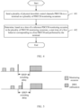
- FIG. 4 is a flowchart of another time determining method according to an embodiment of this application. The method is applied to a network device, and as shown in FIG. 4 , includes the following steps.
- Step 401 Send a plurality of physical downlink control channels PDCCHs to a terminal on a plurality of PDCCH monitoring occasions, where the plurality of PDCCHs are PDCCH repetition transmissions, or information indicated by the plurality of PDCCHs is at least partially the same.
- Step 402 Determine, based on a time of a reference PDCCH monitoring occasion in the plurality of PDCCH monitoring occasions, a start time of a first behavior corresponding to a first PDCCH and performed by the terminal.
- the first PDCCH is any one PDCCH in the plurality of PDCCHs.
- the first behavior includes at least one of the following:
- the inactivity timer includes at least one of the following:
- the determining, based on a time of a reference PDCCH monitoring occasion in the plurality of PDCCH monitoring occasions, a start time of a first behavior corresponding to a first PDCCH and performed by the terminal includes: determining, based on the time of the reference PDCCH monitoring occasion in the plurality of PDCCH monitoring occasions and a BWP switching delay, the start time of the first behavior corresponding to the first PDCCH and performed by the terminal, where the start time of the first behavior includes one of the following:
- the switching time of the BWP switching or the start or restart time of the BWP inactivity timer includes:
- the start time of the discontinuous reception inactivity timer is a start time that is determined based on the time of the reference PDCCH monitoring occasion.
- the determining, based on a time of a reference PDCCH monitoring occasion in the plurality of PDCCH monitoring occasions, a start time of a first behavior corresponding to a first PDCCH and performed by the terminal includes: determining a third time after the time of the reference PDCCH monitoring occasion in the plurality of PDCCH monitoring occasions as the start time of the first behavior corresponding to the first PDCCH and performed by the terminal, where a time interval between the third time and the time of the reference PDCCH monitoring occasion is an offset time indicated by the scheduling offset indication.
- the determining, based on a time of a reference PDCCH monitoring occasion in the plurality of PDCCH monitoring occasions, a start time of a first behavior corresponding to a first PDCCH and performed by the terminal includes: determining a fourth time after the time of the reference PDCCH monitoring occasion as a start time of changing a minimum scheduling offset of the terminal to a minimum scheduling offset indicated by the first PDCCH, where the fourth time is the same as the minimum scheduling offset indicated by the first PDCCH, and a time interval between the fourth time and the time of the reference PDCCH monitoring occasion is equal to a validation time of an updated scheduling offset indication that is pre-obtained.
- the time of the reference PDCCH monitoring occasion includes one of the following:
- the reference PDCCH monitoring occasion is a last monitoring occasion in the plurality of PDCCH monitoring occasions; or the reference PDCCH monitoring occasion is a last monitoring occasion in valid monitoring occasions of the plurality of PDCCH monitoring occasions.
- the plurality of PDCCH monitoring occasions are a plurality of PDCCH monitoring occasions indicated by a search space set that is configured by a network side.
- this embodiment is an implementation of the network device side corresponding to the embodiment shown in FIG. 2 .
- the terminal can also obtain HARQ-ACK related information.
- the terminal switches to the new BWP. If the network has configured PDCCH repetition, or the network has configured the terminal to receive, in a plurality of PDCCH MOs, PDCCHs indicating same information (or indicating partially same information), N PDCCH transmissions or monitorings are performed. Then, after detecting any one PDCCH in the N PDCCH MOs, the terminal performs BWP switching on the reference PDCCH MO, that is, starts or restarts the bwpInactivityTimer from the subframe or slot in which the reference PDCCH MO is located.
- bandwidth part indicator field bandwidth part indicator field
- a time point at which the terminal starts to perform BWP switching or a time point at which the bwpInactivityTimer is started or restarted may be determined by using a time of the reference PDCCH MO as a reference time point.
- the time of the reference PDCCH MO may include one of the following:
- the reference PDCCH MO may be:
- a PDCCH scrambled by a power saving radio network temporary identifier that is, DCI format-2-6
- PS-RNTI Power saving Radio Network Temporary identifier
- DCI format-2-6 not only indicates whether drxInactivityTimer is started in a next DRX cycle (DRX Cycle) in a primary cell (Primary Cell, PCell) or a primary secondary cell (Primary Secondary Cell, PSCell), and also indicates that an active BWP of the Scell is a dormant BWP or a non-dormant BWP.
- the terminal detects the PDCCH, and the active BWP indicated in the PDCCH is different from the current active BWP, the terminal also performs BWP switching in the Scell.
- the network may configure the N PDCCH MOs of the PDCCH in at least one CORESET and at least one search space set. If the terminal detects the PDCCH in any one of N ⁇ 1 MO, the terminal performs BWP switching after the reference PDCCH MO.
- a time point at which the terminal starts to perform BWP switching or a time point at which the bwpInactivityTimer is started or restarted may be determined by using a reference occasion (occasion) of the reference PDCCH MO as a reference time point.
- a reference occasion (occasion) of the reference PDCCH MO as a reference time point.
- the terminal may advance or delay the time of BWP switching as much as possible.
- the time at which BWP switching is performed or the bwpInactivityTimer starts to run is an earlier or later slot, symbol, or subframe in X slots, symbols, or subframes before the start time of drxInactivityTimer and the determined time of the reference PDCCH MO.
- a later time point is used as the time at which BWP switching is performed or the bwpInactivityTimer starts to run.
- the determined time of the reference PDCCH MO may be a reference occasion, which may specifically be one of the following:
- the reference PDCCH MO may be:
- BWP switching can be completed earlier to implement transmission or reception; or when BWP switching is performed at a later time, the purpose of saving power of the terminal can be achieved.
- DRX is configured for the terminal and the terminal detects a PDCCH for PDSCH scheduling or PUSCH scheduling within an active time of DRX
- the terminal starts or restarts the drxInactivityTimer.
- the network configures PDCCH repetition, or the network configures the terminal to receive, in a plurality of PDCCH monitoring occasions (MO), PDCCHs indicating same information (or indicating partially same information), performs N PDCCH transmissions or monitorings are performed. Then, after detecting any one PDCCH in the N PDCCH monitoring occasions, the terminal determines, at the time of the reference PDCCH MO, the time of starting or restarting the drxInactivityTimer.
- the time of the reference PDCCH MO may include one of the following:
- the reference PDCCH MO may be:
- the network may configure a minimum scheduling offset indication (minimumSchedulingOffset) for the terminal, and the signaling is used to indicate a minimum value of k0 or k2 on the BWP, where k0 is a slot offset between the PDCCH and the scheduled PDSCH/CSI-RS, and k2 is a slot offset of the PDCCH and the scheduled PUSCH/SRS.
- k0 is a slot offset between the PDCCH and the scheduled PDSCH/CSI-RS
- k2 is a slot offset of the PDCCH and the scheduled PUSCH/SRS.
- scheduling DCI includes a minimum scheduling offset indication.
- the minimum scheduling offset indication is different from a current minimum scheduling offset indication, the terminal uses the updated minimum scheduling offset indication according to the indication in a time T after reception of the indication. In other words, before the time T, an unupdated minimum scheduling offset indication is still used. That is, the time T is a validation time of the updated minimum scheduling offset time.
- the network configures PDCCH repetition, or the network configures the terminal to receive, in a plurality of PDCCH monitoring occasions (MO), PDCCHs indicating same information (or indicating partially same information), N PDCCH transmissions or monitorings are performed. Then, after detecting any one PDCCH in the N PDCCH MOs, the terminal determines, based on the time of the reference PDCCH MO, that the updated minimum scheduling offset value takes effect after the time T. That is, the updated minimum scheduling offset indication is used after the time T to determine a time offset of a PDSCH or PUSCH resource relative to the reference PDCCH MO.
- the time of the reference PDCCH MO may include one of the following:
- the reference PDCCH MO may be:
- the network may configure for the terminal search space set group switching, that is, configures a plurality of SS set groups, and the network indicates, by using the PDCCH, the terminal to switch the SS set group.
- the SS set group includes at least one SS set.
- the network configures PDCCH repetition, or the network configures the terminal to receive, in a plurality of PDCCH monitoring occasions (MO), PDCCHs indicating same information (or indicating partially same information), N PDCCH transmissions or monitorings are performed. Then, after detecting any one PDCCH in the N PDCCH MOs, the UE determines, based on the time of the reference PDCCH MO, that the updated SS set group takes effect after the time T. That is, a configuration of an SS set of the updated SS set group indicated by the PDCCH is used for PDCCH monitoring after the time T.
- PDCCH monitoring occasions MO
- the time of the reference PDCCH MO may include one of the following:
- the reference PDCCH MO may be:
- the start time of the terminal behavior and the time at which various timers start to run may be determined based on the reference PDCCH monitoring occasion for PDCCH repetition.
- the network and the terminal have clear understanding on the execution time of the terminal behavior based on the reference PDCCH monitoring occasion.
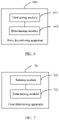
- FIG. 6 is a structural diagram of a time determining apparatus according to an embodiment of this application.
- the apparatus is applied to a terminal, and as shown in FIG. 6 , the time determining apparatus 600 includes:
- the first behavior includes at least one of the following:
- the inactivity timer includes at least one of the following:
- the determining module 602 is configured to determine, based on the time of the reference PDCCH monitoring occasion in the plurality of PDCCH monitoring occasions and a BWP switching delay, the start time of the first behavior corresponding to the first PDCCH, where the start time of the first behavior includes one of the following:
- the switching time of the BWP switching or the start or restart time of the BWP inactivity timer includes:
- the start time of the discontinuous reception inactivity timer is a start time that is determined based on the time of the reference PDCCH monitoring occasion.
- the determining module 602 is configured to determine a third time after the time of the reference PDCCH monitoring occasion in the plurality of PDCCH monitoring occasions as the start time of the first behavior corresponding to the first PDCCH, where a time interval between the third time and the time of the reference PDCCH monitoring occasion is an offset time indicated by the scheduling offset indication.
- the determining module 602 is configured to determine a fourth time after the time of the reference PDCCH monitoring occasion as a start time of changing a minimum scheduling offset of the terminal to a minimum scheduling offset indicated by the first PDCCH, where the fourth time is the same as the minimum scheduling offset indicated by the first PDCCH, and a time interval between the fourth time and the time of the reference PDCCH monitoring occasion is equal to a validation time of an updated scheduling offset indication that is pre-obtained.
- the time of the reference PDCCH monitoring occasion includes one of the following:
- the reference PDCCH monitoring occasion is a last monitoring occasion in the plurality of PDCCH monitoring occasions; or the reference PDCCH monitoring occasion is a last monitoring occasion in valid monitoring occasions of the plurality of PDCCH monitoring occasions.
- the plurality of PDCCH monitoring occasions are a plurality of PDCCH monitoring occasions indicated by a search space set that is configured by a network side.
- the time determining apparatus provided in this embodiment of this application can implement the processes of the method embodiment of FIG. 2 . To avoid repetition, details are not repeated herein. Transmission performance between the terminal and the network side can be improved.
- time determining apparatus in this embodiment of this application may be an apparatus, or may be a component, an integrated circuit, or a chip in a terminal.
- FIG. 7 is a structural diagram of a time determining apparatus according to an embodiment of this application.
- the apparatus is applied to a network device, and as shown in FIG. 7 , the time determining apparatus 700 includes:
- the first PDCCH is any one PDCCH in the plurality of PDCCHs.
- the first behavior includes at least one of the following:
- the inactivity timer includes at least one of the following:
- the determining module 702 is configured to determine, based on the time of the reference PDCCH monitoring occasion in the plurality of PDCCH monitoring occasions and a BWP switching delay, the start time of the first behavior corresponding to the first PDCCH and performed by the terminal, where the start time of the first behavior includes one of the following:
- the switching time of the BWP switching or the start or restart time of the BWP inactivity timer includes:
- the start time of the discontinuous reception inactivity timer is a start time that is determined based on the time of the reference PDCCH monitoring occasion.
- the determining module 702 is configured to determine a third time after the time of the reference PDCCH monitoring occasion in the plurality of PDCCH monitoring occasions as the start time of the first behavior corresponding to the first PDCCH and performed by the terminal, where a time interval between the third time and the time of the reference PDCCH monitoring occasion is an offset time indicated by the scheduling offset indication.
- the determining module 702 is configured to determine a fourth time after the time of the reference PDCCH monitoring occasion as a start time of changing a minimum scheduling offset of the terminal to a minimum scheduling offset indicated by the first PDCCH, where the fourth time is the same as the minimum scheduling offset indicated by the first PDCCH, and a time interval between the fourth time and the time of the reference PDCCH monitoring occasion is equal to a validation time of an updated scheduling offset indication that is pre-obtained.
- the time of the reference PDCCH monitoring occasion includes one of the following:
- the reference PDCCH monitoring occasion is a last monitoring occasion in the plurality of PDCCH monitoring occasions; or the reference PDCCH monitoring occasion is a last monitoring occasion in valid monitoring occasions of the plurality of PDCCH monitoring occasions.
- the plurality of PDCCH monitoring occasions are a plurality of PDCCH monitoring occasions indicated by a search space set that is configured by a network side.
- the time determining apparatus provided in this embodiment of this application can implement the processes of the method embodiment of FIG. 2 . To avoid repetition, details are not repeated herein. Transmission performance between the terminal and the network side can be improved.
- time determining apparatus in this embodiment of this application may be an apparatus, or may be a component, an integrated circuit, or a chip in a network device.
- FIG. 8 is a schematic diagram of a hardware structure of a terminal for implementing the embodiments of this application.
- the terminal 800 includes but is not limited to components such as a radio frequency unit 801, a network module 802, an audio output unit 803, an input unit 804, a sensor 805, a display unit 806, a user input unit 807, an interface unit 808, a memory 809, and a processor 810.
- the terminal 800 may further include a power supply (for example, a battery) supplying power to the components, and the power supply may be logically connected to the processor 810 through a power management system. In this way, functions such as charge management, discharge management, and power consumption management are implemented by using the power management system.
- a power supply for example, a battery
- functions such as charge management, discharge management, and power consumption management are implemented by using the power management system.
- the structure of the electronic device shown in FIG. 8 does not constitute any limitation on the electronic device.
- the electronic device may include more or fewer components than shown in the figure, or a combination of some components, or the components disposed differently. Details are not repeated herein.
- the radio frequency module 801 is configured to perform monitoring on a first physical downlink control channel PDCCH monitoring occasion in a plurality of PDCCH monitoring occasions, so as to detect a first PDCCH.
- the processor 810 is configured to determine, based on a time of a reference PDCCH monitoring occasion in the plurality of PDCCH monitoring occasions, a start time of a first behavior corresponding to the first PDCCH.
- the plurality of PDCCH monitoring occasions are monitoring occasions for performing repetition transmission of the first PDCCH; or information indicated by a plurality of PDCCHs is at least partially the same, where the plurality of PDCCHs are PDCCHs transmitted on the plurality of PDCCH monitoring occasions.
- the first behavior includes at least one of the following:
- the inactivity timer includes at least one of the following:
- the determining, based on a time of a reference PDCCH monitoring occasion in the plurality of PDCCH monitoring occasions, a start time of a first behavior corresponding to the first PDCCH includes: determining, based on the time of the reference PDCCH monitoring occasion in the plurality of PDCCH monitoring occasions and a BWP switching delay, the start time of the first behavior corresponding to the first PDCCH, where the start time of the first behavior includes one of the following:
- the switching time of the BWP switching or the start or restart time of the BWP inactivity timer includes:
- the start time of the discontinuous reception inactivity timer is a start time that is determined based on the time of the reference PDCCH monitoring occasion.
- the determining, based on a time of a reference PDCCH monitoring occasion in the plurality of PDCCH monitoring occasions, a start time of a first behavior corresponding to the first PDCCH includes: determining a third time after the time of the reference PDCCH monitoring occasion in the plurality of PDCCH monitoring occasions as the start time of the first behavior corresponding to the first PDCCH, where a time interval between the third time and the time of the reference PDCCH monitoring occasion is an offset time indicated by the scheduling offset indication.
- the determining, based on a time of a reference PDCCH monitoring occasion in the plurality of PDCCH monitoring occasions, a start time of a first behavior corresponding to the first PDCCH includes: determining a fourth time after the time of the reference PDCCH monitoring occasion as a start time of changing a minimum scheduling offset of the terminal to a minimum scheduling offset indicated by the first PDCCH, where the fourth time is the same as the minimum scheduling offset indicated by the first PDCCH, and a time interval between the fourth time and the time of the reference PDCCH monitoring occasion is equal to a validation time of an updated scheduling offset indication that is pre-obtained.
- the time of the reference PDCCH monitoring occasion includes one of the following:
- the reference PDCCH monitoring occasion is a last monitoring occasion in the plurality of PDCCH monitoring occasions; or the reference PDCCH monitoring occasion is a last monitoring occasion in valid monitoring occasions of the plurality of PDCCH monitoring occasions.
- the plurality of PDCCH monitoring occasions are a plurality of PDCCH monitoring occasions indicated by a search space set that is configured by a network side.
- the terminal can improve transmission performance between the terminal and the network side.
- an embodiment of this application further provides a terminal, including a processor 810, a memory 809, and a program or an instruction stored in the memory 809 and capable of running on the processor 810.
- a terminal including a processor 810, a memory 809, and a program or an instruction stored in the memory 809 and capable of running on the processor 810.
- the program or the instruction is executed by the processor 810, the processes of the foregoing time determining method embodiments are implemented, with the same technical effects achieved. To avoid repetition, details are not described herein again.
- FIG. 9 is a structural diagram of a network device according to an embodiment of this application.
- the network device 900 includes a processor 901, a transceiver 902, a memory 903, and a bus interface.
- the transceiver 902 sends a plurality of physical downlink control channels PDCCHs to a terminal on a plurality of PDCCH monitoring occasions, where the plurality of PDCCHs are PDCCH repetition transmissions, or information indicated by the plurality of PDCCHs is at least partially the same.
- the processor 901 is configured to determine, based on a time of a reference PDCCH monitoring occasion in the plurality of PDCCH monitoring occasions, a start time of a first behavior corresponding to a first PDCCH and performed by the terminal.
- the first PDCCH is any one PDCCH in the plurality of PDCCHs.
- the first behavior includes at least one of the following:
- the inactivity timer includes at least one of the following:
- the determining, based on a time of a reference PDCCH monitoring occasion in the plurality of PDCCH monitoring occasions, a start time of a first behavior corresponding to a first PDCCH and performed by the terminal includes: determining, based on the time of the reference PDCCH monitoring occasion in the plurality of PDCCH monitoring occasions and a BWP switching delay, the start time of the first behavior corresponding to the first PDCCH and performed by the terminal, where the start time of the first behavior includes one of the following:
- the switching time of the BWP switching or the start or restart time of the BWP inactivity timer includes:
- the start time of the discontinuous reception inactivity timer is a start time that is determined based on the time of the reference PDCCH monitoring occasion.
- the determining, based on a time of a reference PDCCH monitoring occasion in the plurality of PDCCH monitoring occasions, a start time of a first behavior corresponding to a first PDCCH and performed by the terminal includes: determining a third time after the time of the reference PDCCH monitoring occasion in the plurality of PDCCH monitoring occasions as the start time of the first behavior corresponding to the first PDCCH and performed by the terminal, where a time interval between the third time and the time of the reference PDCCH monitoring occasion is an offset time indicated by the scheduling offset indication.
- the determining, based on a time of a reference PDCCH monitoring occasion in the plurality of PDCCH monitoring occasions, a start time of a first behavior corresponding to a first PDCCH and performed by the terminal includes: determining a fourth time after the time of the reference PDCCH monitoring occasion as a start time of changing a minimum scheduling offset of the terminal to a minimum scheduling offset indicated by the first PDCCH, where the fourth time is the same as the minimum scheduling offset indicated by the first PDCCH, and a time interval between the fourth time and the time of the reference PDCCH monitoring occasion is equal to a validation time of an updated scheduling offset indication that is pre-obtained.
- the time of the reference PDCCH monitoring occasion includes one of the following:
- the reference PDCCH monitoring occasion is a last monitoring occasion in the plurality of PDCCH monitoring occasions; or the reference PDCCH monitoring occasion is a last monitoring occasion in valid monitoring occasions of the plurality of PDCCH monitoring occasions.
- the plurality of PDCCH monitoring occasions are a plurality of PDCCH monitoring occasions indicated by a search space set that is configured by a network side.
- the network device can improve transmission performance between the terminal and the network side.
- the transceiver 902 is configured to receive and send data under control of the processor 901.
- the transceiver 902 includes at least two antenna ports.
- a bus architecture may include any quantity of interconnected buses and bridges, specifically for interconnecting various circuits of one or more processors represented by the processor 901 and a memory represented by the memory 903.
- the bus architecture may further interconnect various other circuits such as a peripheral device, a voltage regulator, and a power management circuit. These are all well known in the art, and therefore are not further described in this specification.
- the bus interface provides an interface.
- the transceiver 902 may be a plurality of components, that is, the transceiver 902 includes a transmitter and a receiver, and provides a unit for communicating with various other apparatuses on a transmission medium.
- the user interface 904 may also be an interface for externally or internally connecting a required device, and the connected device includes but is not limited to a mini keyboard, a display, a speaker, a microphone, a joystick, or the like.
- the processor 901 is responsible for management of the bus architecture and general processing, and the memory 903 is capable of storing data that is used by the processor 901 during operation.
- an embodiment of this application further provides a network device, including a processor 901, a memory 903, and a program or an instruction stored in the memory 903 and capable of running on the processor 901.
- a network device including a processor 901, a memory 903, and a program or an instruction stored in the memory 903 and capable of running on the processor 901.
- the program or the instruction is executed by the processor 901
- the processes of the foregoing time determining method embodiments are implemented, with the same technical effects achieved. To avoid repetition, details are not described herein again.
- An embodiment of this application further provides a readable storage medium, where a program or an instruction is stored in the readable storage medium.
- a program or an instruction is stored in the readable storage medium.
- the processor is a processor in the terminal or the network device described in the foregoing embodiments.
- the readable storage medium includes a computer-readable storage medium, for example, a computer read-only memory (Read-Only Memory, ROM), a random access memory (Random Access Memory, RAM), a magnetic disk, or an optical disc.
- An embodiment of this application further provides a chip, where the chip includes a processor and a communications interface.
- the communications interface is coupled to the processor, and the processor is configured to run a program or an instruction to implement the processes of the foregoing embodiments of the time determining methods on the terminal side or the network device side, with the same technical effects achieved. To avoid repetition, details are not described herein again.
- the chip mentioned in the embodiments of this application may also be referred to as a system-level chip, a system chip, a chip system, a system-on-chip, or the like.
- the methods in the foregoing embodiments may be implemented by using software in combination with a necessary common hardware platform, and certainly may alternatively be implemented by using hardware. However, in most cases, the former is a preferred implementation.
- the technical solutions of this application essentially or the part contributing to the prior art may be implemented in a form of a software product.
- the software product is stored in a storage medium (such as a ROM/RAM, a magnetic disk, or an optical disc), and includes several instructions for instructing a terminal (which may be a mobile phone, a computer, a server, an air conditioner, a network device, or the like) to perform the methods described in the embodiments of this application.
Landscapes
- Engineering & Computer Science (AREA)
- Signal Processing (AREA)
- Computer Networks & Wireless Communication (AREA)
- Mobile Radio Communication Systems (AREA)
Applications Claiming Priority (2)
| Application Number | Priority Date | Filing Date | Title |
|---|---|---|---|
| CN202010388622.1A CN113630881B (zh) | 2020-05-09 | 2020-05-09 | 时间确定方法、装置、终端和网络设备 |
| PCT/CN2021/091863 WO2021227917A1 (zh) | 2020-05-09 | 2021-05-06 | 时间确定方法、装置、终端和网络设备 |
Publications (3)
| Publication Number | Publication Date |
|---|---|
| EP4149191A1 true EP4149191A1 (de) | 2023-03-15 |
| EP4149191A4 EP4149191A4 (de) | 2023-10-25 |
| EP4149191B1 EP4149191B1 (de) | 2025-01-01 |
Family
ID=78377568
Family Applications (1)
| Application Number | Title | Priority Date | Filing Date |
|---|---|---|---|
| EP21803758.8A Active EP4149191B1 (de) | 2020-05-09 | 2021-05-06 | Verfahren und vorrichtungen zur zeitbestimmung, chip und computerlesbares speichermedium |
Country Status (9)
| Country | Link |
|---|---|
| US (1) | US12500719B2 (de) |
| EP (1) | EP4149191B1 (de) |
| JP (1) | JP7478258B2 (de) |
| KR (1) | KR102887193B1 (de) |
| CN (2) | CN119071921A (de) |
| ES (1) | ES3009337T3 (de) |
| HU (1) | HUE070200T2 (de) |
| PT (1) | PT4149191T (de) |
| WO (1) | WO2021227917A1 (de) |
Families Citing this family (10)
| Publication number | Priority date | Publication date | Assignee | Title |
|---|---|---|---|---|
| WO2021255712A1 (en) * | 2020-06-19 | 2021-12-23 | Lenovo (Singapore) Pte. Ltd. | Power efficient pdcch monitoring |
| US12543187B2 (en) * | 2020-11-06 | 2026-02-03 | Beijing Xiaomi Mobile Software Co., Ltd. | Communication method, electronic device and storage medium |
| US12598488B2 (en) * | 2021-01-16 | 2026-04-07 | Qualcomm Incorporated | Physical downlink control channel repetition in the presence of search space set switching |
| WO2022163559A1 (ja) * | 2021-01-29 | 2022-08-04 | 株式会社Nttドコモ | 端末、無線通信方法及び基地局 |
| CN116264743B (zh) * | 2021-12-13 | 2025-11-25 | 维沃移动通信有限公司 | 参考确定方法、装置、通信设备及可读存储介质 |
| CN116455514B (zh) * | 2022-01-10 | 2025-11-14 | 大唐移动通信设备有限公司 | Pdcch检测方法、装置、终端及存储介质 |
| US20230337255A1 (en) * | 2022-04-15 | 2023-10-19 | Acer Incorporated | Device and Method for Handling Search Space Set Group and Transmission Configuration Indicator State |
| US20240040523A1 (en) * | 2022-07-27 | 2024-02-01 | Qualcomm Incorporated | Adjusting Awake Times for Uplink and Downlink Spanning Multiple Protocols |
| CN120434711A (zh) * | 2024-01-26 | 2025-08-05 | 荣耀终端股份有限公司 | 通信方法与装置、终端设备和网络设备 |
| WO2026016146A1 (en) * | 2024-07-18 | 2026-01-22 | Nec Corporation | Devices and methods for communication |
Family Cites Families (14)
| Publication number | Priority date | Publication date | Assignee | Title |
|---|---|---|---|---|
| WO2014094212A1 (zh) * | 2012-12-17 | 2014-06-26 | 华为技术有限公司 | 一种分时监听方法、设备及系统 |
| EP3281479B1 (de) * | 2015-04-09 | 2019-10-30 | LG Electronics Inc. | Verfahren zur durchführung von pdcch-überwachung in einer trägeraggregation mit mindestens einer scell, die in einem unlizenzierten spektrum operiert, und vorrichtung dafür |
| CN109429258B (zh) * | 2017-07-17 | 2021-10-29 | 中国移动通信有限公司研究院 | 一种信道监听的指示方法、监听方法、终端及网络侧设备 |
| CN110324127B (zh) * | 2018-03-30 | 2022-01-25 | 维沃移动通信有限公司 | Pdcch监听候选的分配方法和网络侧设备 |
| CN110351019B (zh) * | 2018-04-04 | 2020-12-15 | 华为技术有限公司 | 通信方法和装置 |
| CN112020891B (zh) * | 2018-06-26 | 2022-03-01 | Oppo广东移动通信有限公司 | 一种下行控制信道的检测方法及装置、终端设备 |
| US20200022144A1 (en) * | 2018-07-09 | 2020-01-16 | Samsung Electronics Co., Ltd. | Overhead reduction and reliability enhancements for dl control signaling |
| US11464008B2 (en) | 2018-07-12 | 2022-10-04 | Qualcomm Incorporated | Determination rule of PDSCH scheduled slot with PDCCH repetition |
| CN110719635B (zh) * | 2018-07-13 | 2021-09-17 | 维沃移动通信有限公司 | 一种信道检测指示方法、终端及网络设备 |
| KR102836757B1 (ko) * | 2018-09-10 | 2025-07-21 | 한국전자통신연구원 | 비면허 대역에서 신호의 송수신을 위한 방법 및 장치 |
| WO2020072963A1 (en) * | 2018-10-05 | 2020-04-09 | Intel Corporation | Pdcch monitoring span and dci format set determination |
| CN111132330B (zh) * | 2018-11-01 | 2024-04-09 | 北京三星通信技术研究有限公司 | Pdcch监听方法、装置、电子设备及计算机可读存储介质 |
| CN112997568B (zh) * | 2018-11-02 | 2023-02-07 | 华为技术有限公司 | 数据调度的方法、设备及系统 |
| JP7249785B2 (ja) * | 2019-01-10 | 2023-03-31 | シャープ株式会社 | 端末装置、基地局装置、および通信方法 |
-
2020
- 2020-05-09 CN CN202411130386.8A patent/CN119071921A/zh active Pending
- 2020-05-09 CN CN202010388622.1A patent/CN113630881B/zh active Active
-
2021
- 2021-05-06 KR KR1020227042793A patent/KR102887193B1/ko active Active
- 2021-05-06 EP EP21803758.8A patent/EP4149191B1/de active Active
- 2021-05-06 PT PT218037588T patent/PT4149191T/pt unknown
- 2021-05-06 HU HUE21803758A patent/HUE070200T2/hu unknown
- 2021-05-06 WO PCT/CN2021/091863 patent/WO2021227917A1/zh not_active Ceased
- 2021-05-06 ES ES21803758T patent/ES3009337T3/es active Active
- 2021-05-06 JP JP2022568476A patent/JP7478258B2/ja active Active
-
2022
- 2022-11-09 US US17/983,864 patent/US12500719B2/en active Active
Also Published As
| Publication number | Publication date |
|---|---|
| US20230072069A1 (en) | 2023-03-09 |
| CN119071921A (zh) | 2024-12-03 |
| JP2023524869A (ja) | 2023-06-13 |
| US12500719B2 (en) | 2025-12-16 |
| PT4149191T (pt) | 2025-01-23 |
| KR20230007489A (ko) | 2023-01-12 |
| ES3009337T3 (en) | 2025-03-26 |
| CN113630881B (zh) | 2024-08-06 |
| KR102887193B1 (ko) | 2025-11-14 |
| CN113630881A (zh) | 2021-11-09 |
| WO2021227917A1 (zh) | 2021-11-18 |
| HUE070200T2 (hu) | 2025-05-28 |
| WO2021227917A9 (zh) | 2022-11-24 |
| EP4149191A4 (de) | 2023-10-25 |
| EP4149191B1 (de) | 2025-01-01 |
| JP7478258B2 (ja) | 2024-05-02 |
Similar Documents
| Publication | Publication Date | Title |
|---|---|---|
| US12500719B2 (en) | Time determining method and apparatus, terminal, and network device | |
| US11968623B2 (en) | Method and apparatus having a discontinuous reception configuration | |
| EP3963953B1 (de) | Bestimmung der pdcch-überwachung während der einschaltdauer im energiesparmodus | |
| CN114424482B (zh) | 通信方法及装置 | |
| CN111356213B (zh) | 一种信息传输方法、基站及终端 | |
| EP3565368A1 (de) | Signalübertragungsverfahren zum diskontinuierlichen empfang, endgerätevorrichtung und netzwerkvorrichtung | |
| US20250071685A1 (en) | Signal processing method, terminal, and network device | |
| EP4192123A1 (de) | Informationsanzeigeverfahren und -vorrichtung, endgerätevorrichtung und netzwerkvorrichtung | |
| JP2023534543A (ja) | 補助情報送信方法、受信方法、装置、端末及びネットワーク側機器 | |
| US20240340797A1 (en) | Drx communications method, terminal and computer readable storage medium | |
| CN116709544A (zh) | 一种drx传输方法及相关设备 | |
| EP3793324B1 (de) | Einstellung der länge einer nicht vorhersagbaren periode | |
| US20240283617A1 (en) | Resource selection method and apparatus, and terminal | |
| CN117063496A (zh) | 用于多播及广播服务的drx操作的方法及装置 | |
| EP4415427A1 (de) | Kommunikationsverfahren und -vorrichtung | |
| CN114009098B (zh) | 不连续接收配置的状态的通知 | |
| CN121968138A (zh) | 一种信息配置方法、通信节点及存储介质 | |
| WO2025209547A1 (zh) | 通信方法及装置、计算机程序产品及可读存储介质 |
Legal Events
| Date | Code | Title | Description |
|---|---|---|---|
| STAA | Information on the status of an ep patent application or granted ep patent |
Free format text: STATUS: THE INTERNATIONAL PUBLICATION HAS BEEN MADE |
|
| PUAI | Public reference made under article 153(3) epc to a published international application that has entered the european phase |
Free format text: ORIGINAL CODE: 0009012 |
|
| STAA | Information on the status of an ep patent application or granted ep patent |
Free format text: STATUS: REQUEST FOR EXAMINATION WAS MADE |
|
| 17P | Request for examination filed |
Effective date: 20221205 |
|
| AK | Designated contracting states |
Kind code of ref document: A1 Designated state(s): AL AT BE BG CH CY CZ DE DK EE ES FI FR GB GR HR HU IE IS IT LI LT LU LV MC MK MT NL NO PL PT RO RS SE SI SK SM TR |
|
| DAV | Request for validation of the european patent (deleted) | ||
| DAX | Request for extension of the european patent (deleted) | ||
| REG | Reference to a national code |
Ref country code: DE Ref legal event code: R079 Ref country code: DE Ref legal event code: R079 Ref document number: 602021024353 Country of ref document: DE Free format text: PREVIOUS MAIN CLASS: H04W0072040000 Ipc: H04L0005000000 |
|
| A4 | Supplementary search report drawn up and despatched |
Effective date: 20230922 |
|
| RIC1 | Information provided on ipc code assigned before grant |
Ipc: H04L 1/18 20230101ALN20230918BHEP Ipc: H04W 76/28 20180101ALN20230918BHEP Ipc: H04W 68/00 20090101ALN20230918BHEP Ipc: H04W 68/02 20090101ALI20230918BHEP Ipc: H04W 72/232 20230101ALI20230918BHEP Ipc: H04L 5/00 20060101AFI20230918BHEP |
|
| GRAP | Despatch of communication of intention to grant a patent |
Free format text: ORIGINAL CODE: EPIDOSNIGR1 |
|
| STAA | Information on the status of an ep patent application or granted ep patent |
Free format text: STATUS: GRANT OF PATENT IS INTENDED |
|
| RIC1 | Information provided on ipc code assigned before grant |
Ipc: H04L 1/08 20060101ALN20240722BHEP Ipc: H04W 76/28 20180101ALN20240722BHEP Ipc: H04W 68/00 20090101ALN20240722BHEP Ipc: H04W 68/02 20090101ALI20240722BHEP Ipc: H04W 72/232 20230101ALI20240722BHEP Ipc: H04L 5/00 20060101AFI20240722BHEP |
|
| INTG | Intention to grant announced |
Effective date: 20240731 |
|
| GRAS | Grant fee paid |
Free format text: ORIGINAL CODE: EPIDOSNIGR3 |
|
| GRAA | (expected) grant |
Free format text: ORIGINAL CODE: 0009210 |
|
| STAA | Information on the status of an ep patent application or granted ep patent |
Free format text: STATUS: THE PATENT HAS BEEN GRANTED |
|
| AK | Designated contracting states |
Kind code of ref document: B1 Designated state(s): AL AT BE BG CH CY CZ DE DK EE ES FI FR GB GR HR HU IE IS IT LI LT LU LV MC MK MT NL NO PL PT RO RS SE SI SK SM TR |
|
| REG | Reference to a national code |
Ref country code: GB Ref legal event code: FG4D |
|
| REG | Reference to a national code |
Ref country code: DE Ref legal event code: R096 Ref document number: 602021024353 Country of ref document: DE |
|
| REG | Reference to a national code |
Ref country code: CH Ref legal event code: EP |
|
| REG | Reference to a national code |
Ref country code: PT Ref legal event code: SC4A Ref document number: 4149191 Country of ref document: PT Date of ref document: 20250123 Kind code of ref document: T Free format text: AVAILABILITY OF NATIONAL TRANSLATION Effective date: 20250117 |
|
| REG | Reference to a national code |
Ref country code: IE Ref legal event code: FG4D |
|
| REG | Reference to a national code |
Ref country code: SE Ref legal event code: TRGR |
|
| REG | Reference to a national code |
Ref country code: NL Ref legal event code: FP |
|
| REG | Reference to a national code |
Ref country code: ES Ref legal event code: FG2A Ref document number: 3009337 Country of ref document: ES Kind code of ref document: T3 Effective date: 20250326 |
|
| REG | Reference to a national code |
Ref country code: LT Ref legal event code: MG9D |
|
| PGFP | Annual fee paid to national office [announced via postgrant information from national office to epo] |
Ref country code: NL Payment date: 20250409 Year of fee payment: 5 |
|
| REG | Reference to a national code |
Ref country code: HU Ref legal event code: AG4A Ref document number: E070200 Country of ref document: HU |
|
| REG | Reference to a national code |
Ref country code: AT Ref legal event code: MK05 Ref document number: 1757403 Country of ref document: AT Kind code of ref document: T Effective date: 20250101 |
|
| PG25 | Lapsed in a contracting state [announced via postgrant information from national office to epo] |
Ref country code: FI Free format text: LAPSE BECAUSE OF FAILURE TO SUBMIT A TRANSLATION OF THE DESCRIPTION OR TO PAY THE FEE WITHIN THE PRESCRIBED TIME-LIMIT Effective date: 20250101 |
|
| PG25 | Lapsed in a contracting state [announced via postgrant information from national office to epo] |
Ref country code: PL Free format text: LAPSE BECAUSE OF FAILURE TO SUBMIT A TRANSLATION OF THE DESCRIPTION OR TO PAY THE FEE WITHIN THE PRESCRIBED TIME-LIMIT Effective date: 20250101 |
|
| PGFP | Annual fee paid to national office [announced via postgrant information from national office to epo] |
Ref country code: DE Payment date: 20250402 Year of fee payment: 5 |
|
| PGFP | Annual fee paid to national office [announced via postgrant information from national office to epo] |
Ref country code: ES Payment date: 20250605 Year of fee payment: 5 |
|
| PG25 | Lapsed in a contracting state [announced via postgrant information from national office to epo] |
Ref country code: NO Free format text: LAPSE BECAUSE OF FAILURE TO SUBMIT A TRANSLATION OF THE DESCRIPTION OR TO PAY THE FEE WITHIN THE PRESCRIBED TIME-LIMIT Effective date: 20250401 Ref country code: IS Free format text: LAPSE BECAUSE OF FAILURE TO SUBMIT A TRANSLATION OF THE DESCRIPTION OR TO PAY THE FEE WITHIN THE PRESCRIBED TIME-LIMIT Effective date: 20250501 |
|
| PGFP | Annual fee paid to national office [announced via postgrant information from national office to epo] |
Ref country code: HU Payment date: 20250429 Year of fee payment: 5 |
|
| PGFP | Annual fee paid to national office [announced via postgrant information from national office to epo] |
Ref country code: IT Payment date: 20250422 Year of fee payment: 5 |
|
| PG25 | Lapsed in a contracting state [announced via postgrant information from national office to epo] |
Ref country code: HR Free format text: LAPSE BECAUSE OF FAILURE TO SUBMIT A TRANSLATION OF THE DESCRIPTION OR TO PAY THE FEE WITHIN THE PRESCRIBED TIME-LIMIT Effective date: 20250101 |
|
| PG25 | Lapsed in a contracting state [announced via postgrant information from national office to epo] |
Ref country code: LV Free format text: LAPSE BECAUSE OF FAILURE TO SUBMIT A TRANSLATION OF THE DESCRIPTION OR TO PAY THE FEE WITHIN THE PRESCRIBED TIME-LIMIT Effective date: 20250101 |
|
| PGFP | Annual fee paid to national office [announced via postgrant information from national office to epo] |
Ref country code: PT Payment date: 20250506 Year of fee payment: 5 |
|
| PGFP | Annual fee paid to national office [announced via postgrant information from national office to epo] |
Ref country code: FR Payment date: 20250401 Year of fee payment: 5 |
|
| PG25 | Lapsed in a contracting state [announced via postgrant information from national office to epo] |
Ref country code: BG Free format text: LAPSE BECAUSE OF FAILURE TO SUBMIT A TRANSLATION OF THE DESCRIPTION OR TO PAY THE FEE WITHIN THE PRESCRIBED TIME-LIMIT Effective date: 20250101 Ref country code: GR Free format text: LAPSE BECAUSE OF FAILURE TO SUBMIT A TRANSLATION OF THE DESCRIPTION OR TO PAY THE FEE WITHIN THE PRESCRIBED TIME-LIMIT Effective date: 20250402 |
|
| PG25 | Lapsed in a contracting state [announced via postgrant information from national office to epo] |
Ref country code: AT Free format text: LAPSE BECAUSE OF FAILURE TO SUBMIT A TRANSLATION OF THE DESCRIPTION OR TO PAY THE FEE WITHIN THE PRESCRIBED TIME-LIMIT Effective date: 20250101 |
|
| PG25 | Lapsed in a contracting state [announced via postgrant information from national office to epo] |
Ref country code: CZ Free format text: LAPSE BECAUSE OF FAILURE TO SUBMIT A TRANSLATION OF THE DESCRIPTION OR TO PAY THE FEE WITHIN THE PRESCRIBED TIME-LIMIT Effective date: 20250101 |
|
| REG | Reference to a national code |
Ref country code: DE Ref legal event code: R097 Ref document number: 602021024353 Country of ref document: DE |
|
| PG25 | Lapsed in a contracting state [announced via postgrant information from national office to epo] |
Ref country code: SM Free format text: LAPSE BECAUSE OF FAILURE TO SUBMIT A TRANSLATION OF THE DESCRIPTION OR TO PAY THE FEE WITHIN THE PRESCRIBED TIME-LIMIT Effective date: 20250101 |
|
| PG25 | Lapsed in a contracting state [announced via postgrant information from national office to epo] |
Ref country code: DK Free format text: LAPSE BECAUSE OF FAILURE TO SUBMIT A TRANSLATION OF THE DESCRIPTION OR TO PAY THE FEE WITHIN THE PRESCRIBED TIME-LIMIT Effective date: 20250101 |
|
| PG25 | Lapsed in a contracting state [announced via postgrant information from national office to epo] |
Ref country code: EE Free format text: LAPSE BECAUSE OF FAILURE TO SUBMIT A TRANSLATION OF THE DESCRIPTION OR TO PAY THE FEE WITHIN THE PRESCRIBED TIME-LIMIT Effective date: 20250101 |
|
| PG25 | Lapsed in a contracting state [announced via postgrant information from national office to epo] |
Ref country code: RO Free format text: LAPSE BECAUSE OF FAILURE TO SUBMIT A TRANSLATION OF THE DESCRIPTION OR TO PAY THE FEE WITHIN THE PRESCRIBED TIME-LIMIT Effective date: 20250101 |
|
| PG25 | Lapsed in a contracting state [announced via postgrant information from national office to epo] |
Ref country code: SK Free format text: LAPSE BECAUSE OF FAILURE TO SUBMIT A TRANSLATION OF THE DESCRIPTION OR TO PAY THE FEE WITHIN THE PRESCRIBED TIME-LIMIT Effective date: 20250101 |
|
| PLBE | No opposition filed within time limit |
Free format text: ORIGINAL CODE: 0009261 |
|
| STAA | Information on the status of an ep patent application or granted ep patent |
Free format text: STATUS: NO OPPOSITION FILED WITHIN TIME LIMIT |
|
| REG | Reference to a national code |
Ref country code: CH Ref legal event code: L10 Free format text: ST27 STATUS EVENT CODE: U-0-0-L10-L00 (AS PROVIDED BY THE NATIONAL OFFICE) Effective date: 20251112 |
|
| 26N | No opposition filed |
Effective date: 20251002 |
|
| REG | Reference to a national code |
Ref country code: CH Ref legal event code: H13 Free format text: ST27 STATUS EVENT CODE: U-0-0-H10-H13 (AS PROVIDED BY THE NATIONAL OFFICE) Effective date: 20251223 |
|
| PG25 | Lapsed in a contracting state [announced via postgrant information from national office to epo] |
Ref country code: LU Free format text: LAPSE BECAUSE OF NON-PAYMENT OF DUE FEES Effective date: 20250506 |
|
| PG25 | Lapsed in a contracting state [announced via postgrant information from national office to epo] |
Ref country code: CH Free format text: LAPSE BECAUSE OF NON-PAYMENT OF DUE FEES Effective date: 20250531 |
|
| REG | Reference to a national code |
Ref country code: BE Ref legal event code: MM Effective date: 20250531 |
|
| PG25 | Lapsed in a contracting state [announced via postgrant information from national office to epo] |
Ref country code: MC Free format text: LAPSE BECAUSE OF FAILURE TO SUBMIT A TRANSLATION OF THE DESCRIPTION OR TO PAY THE FEE WITHIN THE PRESCRIBED TIME-LIMIT Effective date: 20250101 |
|
| PGFP | Annual fee paid to national office [announced via postgrant information from national office to epo] |
Ref country code: SE Payment date: 20260327 Year of fee payment: 6 |
|
| PGFP | Annual fee paid to national office [announced via postgrant information from national office to epo] |
Ref country code: GB Payment date: 20260324 Year of fee payment: 6 |
|
| PG25 | Lapsed in a contracting state [announced via postgrant information from national office to epo] |
Ref country code: IE Free format text: LAPSE BECAUSE OF NON-PAYMENT OF DUE FEES Effective date: 20250506 |
|
| PG25 | Lapsed in a contracting state [announced via postgrant information from national office to epo] |
Ref country code: BE Free format text: LAPSE BECAUSE OF NON-PAYMENT OF DUE FEES Effective date: 20250531 |