EP4149708B1 - Installation pour relier des composants électroniques - Google Patents
Installation pour relier des composants électroniques Download PDFInfo
- Publication number
- EP4149708B1 EP4149708B1 EP21727397.8A EP21727397A EP4149708B1 EP 4149708 B1 EP4149708 B1 EP 4149708B1 EP 21727397 A EP21727397 A EP 21727397A EP 4149708 B1 EP4149708 B1 EP 4149708B1
- Authority
- EP
- European Patent Office
- Prior art keywords
- soldering
- module
- sintering system
- cold trap
- temperature
- Prior art date
- Legal status (The legal status is an assumption and is not a legal conclusion. Google has not performed a legal analysis and makes no representation as to the accuracy of the status listed.)
- Active
Links
Images


Classifications
-
- B—PERFORMING OPERATIONS; TRANSPORTING
- B23—MACHINE TOOLS; METAL-WORKING NOT OTHERWISE PROVIDED FOR
- B23K—SOLDERING OR UNSOLDERING; WELDING; CLADDING OR PLATING BY SOLDERING OR WELDING; CUTTING BY APPLYING HEAT LOCALLY, e.g. FLAME CUTTING; WORKING BY LASER BEAM
- B23K1/00—Soldering, e.g. brazing, or unsoldering
- B23K1/0008—Soldering, e.g. brazing, or unsoldering specially adapted for particular articles or work
- B23K1/0016—Soldering of electronic components
-
- B—PERFORMING OPERATIONS; TRANSPORTING
- B23—MACHINE TOOLS; METAL-WORKING NOT OTHERWISE PROVIDED FOR
- B23K—SOLDERING OR UNSOLDERING; WELDING; CLADDING OR PLATING BY SOLDERING OR WELDING; CUTTING BY APPLYING HEAT LOCALLY, e.g. FLAME CUTTING; WORKING BY LASER BEAM
- B23K3/00—Tools, devices or special appurtenances for soldering, e.g. brazing, or unsoldering, not specially adapted for particular methods
- B23K3/08—Auxiliary devices therefor
- B23K3/085—Cooling, heat sink or heat shielding means
-
- B—PERFORMING OPERATIONS; TRANSPORTING
- B22—CASTING; POWDER METALLURGY
- B22F—WORKING METALLIC POWDER; MANUFACTURE OF ARTICLES FROM METALLIC POWDER; MAKING METALLIC POWDER; APPARATUS OR DEVICES SPECIALLY ADAPTED FOR METALLIC POWDER
- B22F3/00—Manufacture of workpieces or articles from metallic powder characterised by the manner of compacting or sintering; Apparatus specially adapted therefor ; Presses and furnaces
- B22F3/003—Apparatus, e.g. furnaces
-
- B—PERFORMING OPERATIONS; TRANSPORTING
- B23—MACHINE TOOLS; METAL-WORKING NOT OTHERWISE PROVIDED FOR
- B23K—SOLDERING OR UNSOLDERING; WELDING; CLADDING OR PLATING BY SOLDERING OR WELDING; CUTTING BY APPLYING HEAT LOCALLY, e.g. FLAME CUTTING; WORKING BY LASER BEAM
- B23K26/00—Working by laser beam, e.g. welding, cutting or boring
- B23K26/70—Auxiliary operations or equipment
- B23K26/702—Auxiliary equipment
- B23K26/703—Cooling arrangements
-
- B—PERFORMING OPERATIONS; TRANSPORTING
- B23—MACHINE TOOLS; METAL-WORKING NOT OTHERWISE PROVIDED FOR
- B23K—SOLDERING OR UNSOLDERING; WELDING; CLADDING OR PLATING BY SOLDERING OR WELDING; CUTTING BY APPLYING HEAT LOCALLY, e.g. FLAME CUTTING; WORKING BY LASER BEAM
- B23K35/00—Rods, electrodes, materials, or media, for use in soldering, welding, or cutting
- B23K35/22—Rods, electrodes, materials, or media, for use in soldering, welding, or cutting characterised by the composition or nature of the material
- B23K35/38—Selection of media, e.g. special atmospheres for surrounding the working area
- B23K35/383—Selection of media, e.g. special atmospheres for surrounding the working area mainly containing noble gases or nitrogen
-
- B—PERFORMING OPERATIONS; TRANSPORTING
- B22—CASTING; POWDER METALLURGY
- B22F—WORKING METALLIC POWDER; MANUFACTURE OF ARTICLES FROM METALLIC POWDER; MAKING METALLIC POWDER; APPARATUS OR DEVICES SPECIALLY ADAPTED FOR METALLIC POWDER
- B22F2999/00—Aspects linked to processes or compositions used in powder metallurgy
-
- B—PERFORMING OPERATIONS; TRANSPORTING
- B23—MACHINE TOOLS; METAL-WORKING NOT OTHERWISE PROVIDED FOR
- B23K—SOLDERING OR UNSOLDERING; WELDING; CLADDING OR PLATING BY SOLDERING OR WELDING; CUTTING BY APPLYING HEAT LOCALLY, e.g. FLAME CUTTING; WORKING BY LASER BEAM
- B23K2101/00—Articles made by soldering, welding or cutting
- B23K2101/36—Electric or electronic devices
Definitions
- the invention relates to a system for connecting electronic assemblies, in particular a soldering or sintering system with a transport device for transporting the electronic assemblies through the system, comprising several, gas-tight, separable modules for connecting the electronic assemblies to one another, with at least one module as a soldering or Sintering module and a module is designed as a cooling module.
- Such a system can be designed, for example, as a soldering device for producing a soldered connection between several components, in particular electronic assemblies. This can be designed by heating and melting solder material, which is arranged between the components to be connected, and/or by covering a component with solder material for a subsequent connection process. As a rule, the components and the solder material, which can be in the form of solder plates, solder paste or solder powder, are temporarily assembled into a stack before being introduced into the process chamber.
- soldering device large-area connections are produced in particular, in which, for example, semiconductor components, microelectronic components or power semiconductor chips, such as.
- B. Transistors or diodes on circuit boards, IGBTs, MOSFETs or diodes on metallized ceramic substrates or other circuit carriers are soldered or soldered together, or in which metallized ceramic substrates are soldered to metallic base plates and/or heat sinks.
- Circuit boards that are to be connected to heat sinks can also be soldered in a generic soldering device.
- the aim is to heat the melted solder together with the components to be connected in a controlled manner above the melting point of the solder and then cool it in a controlled manner below the solidification point of the solder in order to connect the components together without voids.
- the solder can be a soft or hard solder, especially a tin solder, but also a silver solder, brass solder or phosphorus solder.
- soldered connections usually takes place in a process chamber that is closed off from the environment and in particular can be evacuated, in which, for example, a base plate and a pressure plate can be arranged, between which a soldering group comprising the component or components and the solder material is accommodated.
- the base plate and the pressure plate can be adjustable in terms of their distance relative to one another in order to exert a pressing force on the soldering group.
- the pressure plate and/or the base plate can cause the components and the solder material to be heated and/or cooled.
- the plates mentioned can be thermally coupled to corresponding heat sources and/or heat sinks.
- Such a system can also be designed as a sintering device for producing a workpiece from at least one component using pressure sintering, in particular using low-temperature pressure sintering.
- a sintering device can have an upper tool and a lower tool, between which the at least one component is accommodated, the upper tool and the lower tool being adjustable relative to one another for applying a pressing force to the workpiece to be sintered, and at least one heating device for heating the workpiece to be sintered .
- a solid workpiece can be produced under the influence of heat and pressure from a so-called green body, which consists of a fine- or coarse-grained substance or mixture of substances.
- the contacted surfaces of the connection partners are connected mechanically, thermally and, if necessary, electrically.
- the insert considered here is used in particular for the mechanical and electrical and/or thermally conductive connection of two components, in particular electrical semiconductor components such as high-performance switching elements or semiconductor assemblies and a base body, usually a circuit board, in particular a DCB/AMB'S lead frame (Direct Copper Bonded/Active Metal Braze on a metallic cable carrier or connection frame), a heat sink or the like.
- two or more components in particular electronic components and substrates, can be connected to one another, in particular electrically and/or thermally conductive, by means of a joining material, in which case the connecting joining material is sintered.
- a corresponding device and a method are, for example, from DE 10 2008 009 510 B3 known.
- Other systems can be designed as automatic sintering or soldering systems, in particular automatic multi-chamber systems with several process chambers. These include at least one chamber or a module for electrically and/or thermally connecting an electrical component to another component group, an electrical circuit board or DCBs/AMB'S leadframes or a heat sink.
- components generally includes electronic assemblies, circuit carriers, substrates, substrate carriers, base plates, workpiece carriers, assembly carriers or the like made of metal, ceramic, plastic or other materials or any combination of materials, as well as components to be fastened thereon such as power semiconductor chips, (semiconductor) assemblies or the like.
- Workpiece carriers are often used that can accommodate several components or groups of components at the same time, which can simplify handling and increase throughput rates.
- Such systems can have at least one process chamber that can be closed in a gas-tight manner and in which the components are accommodated during the temperature treatment.
- a specific process atmosphere can be provided in this process chamber, which reduces or prevents undesirable chemical reactions, in particular oxidation of metallic surfaces of the workpiece, and/or triggers, promotes or catalyzes desired chemical reactions.
- the relative oxygen content can be reduced, for example to an oxygen content of 0.005% to 0.3%.
- an inert gas such as nitrogen (N 2 ) can be introduced into the process chamber.
- the process atmosphere can also contain a reducing agent, e.g. B. methanoic acid (CH 2 O 2 ) or nitrogen and hydrogen (N / H) containing forming gas.
- Providing the process atmosphere can also include influencing the pressure conditions, i.e. generating an overpressure or a negative pressure.
- Such systems often include several process chambers in which the components can be exposed to different process conditions or process atmospheres.
- the components or assemblies can be tempered to temperatures below the melting temperature of the solder material
- they can be heated to the soldering temperature and in a third process chamber there can be controlled cooling, with the properties of the process atmosphere changing from process chamber to process chamber can vary or can also be changed over time during the time spent in a respective chamber.
- the components or workpiece carriers in which a number of components are connected to one another simultaneously, rest within the modules in a so-called resting process in contrast to a flow process, which is possible with non-closed modules or process chambers is.
- several components of a flow production transport can be arranged in a workpiece carrier, i.e. clustered, guided through the system in a step-by-step process, and then individually released into another flow production.
- This means that a step-by-step, standing system can also be integrated into a continuous flow production process.
- the clustering and separation can be carried out automatically, with easier quality control and, if necessary, the addition of covers and the like, for example for a sintering process, being possible.
- components thereof e.g. binders or fillers
- binders or fillers can escape into the process atmosphere through sublimation or evaporation, which leads to unwanted contamination or contamination of components, the process chamber, components of the system contained therein or of downstream devices such as pumps, valves or pipes.
- Other substances such as fluxes, adhesives for fixing the components or components of the components to be connected, as well as reaction products of the components and atmospheres mentioned can also lead to such contamination.
- these workpiece carriers can be transported between the different modules or chambers with the help of transport devices also known as running strips.
- the individual chambers can be separated from each other with vacuum flat slides, to provide individually adjustable process atmospheres.
- These vacuum flat valves or locks are usually cooled to protect seals from heat damage.
- the solder material is brought into negative pressure at least twice at a temperature that at least corresponds to the liquidus temperature. Furthermore, methods and devices are shown in which a negative pressure is generated at least before the soldering process begins.
- a method for soldering in the vapor phase is shown, wherein a negative pressure is generated before, during and / or after melting the solder on the solder in the vapor phase zone around the solder.
- a device with two chambers ie a first chamber for the vapor phase zone and a second chamber for the negative pressure, is shown, with either the second chamber being located in the first chamber or being retractable into it.
- the DE 10 2007 005 345 B4 shows a method and a device for reflow soldering of assemblies provided with solder paste in a chamber with heating in the chamber.
- the assemblies are transported into the chamber using a transport mechanism and the chamber is then sealed off. Subsequently, the pressure in the chamber is increased above atmospheric pressure and the temperature is increased by a convection heater to melt the solder paste. While maintaining the temperature, the pressure is then reduced to atmospheric pressure.
- the DE 10 2014 106631 A1 which discloses the preamble of claim 1, shows a device for producing solder connections on assemblies of electronic components and circuit boards and has a transport system for these assemblies and a plurality of pressure chambers.
- the pressure chambers each have an independent heating device and a pressure adjustment device.
- the object of the invention is therefore to propose a system with which deposits of undesirable substances in the different modules and at the soldering points can be reduced or avoided.
- the object of the invention is to create a system in which the formation of deposits of undesirable substances in the modules and on the soldered material is reduced or avoided. It is the object of the invention to minimize the residence time of unwanted condensate on the walls of the module, particularly in closed modules in stationary processes and under controlled atmospheric influence.
- the subject of the invention is a soldering and/or sintering system for connecting electronic assemblies according to claim 1 with a transport device for transporting the electronic assemblies through the system, comprising several, gas-tight, separable modules for connecting the electronic assemblies to one another, with at least one module as solder - and/or sintering module and a module is designed as a cooling module.
- a further module is arranged between the soldering or sintering module and the cooling module, which is designed as a soft cooling module for cooling between a process temperature of the soldering or sintering module and an intermediate temperature, in particular below a solder solidification temperature.
- the soft cooling module is therefore connected upstream of the cooling module, whereby cooling can initially take place to a desired or achieved temperature, which in particular is not equal to the room temperature.
- the temperature to which at least the solder material is cooled in the soft cooling chamber is just below the solder solidification temperature. impurities Due to the soldering process, in particular solder paste residues, on the component or assembly can be avoided because the contaminants do not settle on the solder or condense on the electronic assemblies.
- condensation and deposition of the solder paste residues and/or from the atmosphere on the component or assembly as well as in the module itself can be at least reduced, in particular avoided.
- This is achieved, for example, by specifically causing the solder paste residues to condense in the area of the soft cooling module and preferably depositing there. Therefore, the contaminants can be removed directly from the soft cooling module before the final cooling and preferably do not reach the downstream cooling module. Sticking to the component or assemblies can thereby be avoided, which can improve the quality of the solder connection.
- a system in particular a soldering system, can be provided with reduced contamination of the individual chambers of the soldering process, especially when using solder paste and/or HCOOH.
- the soldering module can have a temperature of, for example, 250 °C.
- the electronic assemblies are preferably cooled to room temperature, ie 20 °C.
- the intermediate soft cooling module allows a so-called first, soft cooling to take place. This is in a range just below the solder solidification temperature.
- the solder solidification temperature is in the range from 150 °C to 220 °C.
- the solder can in particular be a tin or silver solder (AG).
- a further module can be arranged in front of the soldering module, for example a preheating module and/or an introduction module for introducing the electronic assemblies into the system.
- the soft cooling module does not fall under the Pressure Equipment Directive Directive 2014/68/EU.
- 2014/68/EU applies to containers, pipelines and pressure-retaining equipment or equipment with a safety function with an internal overpressure of more than 0.5 bar.
- An excess pressure of less than or equal to 0.5 bar can therefore preferably be present in the soft cooling module.
- the volume of the chamber can be around 50 liters or more, for example, other volumes are also conceivable.
- internal production control can be eliminated, which reduces the time required.
- pressure flooding can take place to 0.5 barg, with this pressure then being maintained.
- the value 0.5 barg means an excess pressure of 0.5 bar above atmospheric pressure.
- the temperature in the soft cooling module can be maintained or increased until the desired excess pressure is built up in the soft cooling module.
- Heating in the soft cooling chamber can generally take place via convection, for example by gas, via contact heating and/or via radiation heating, in particular IR light.
- the system includes a higher-level control system. This can be used to control all modules in the system.
- at least one module can have its own primary control circuit and/or safety circuit. This means that individual modules and/or individual work steps can be replaced without having to completely reprogram the higher-level control system.
- more than one module, in particular two or more modules can have their own control circuit and/or safety circuit.
- the soft cooling module can be set up to provide an overpressure of a process atmosphere of 1 bar, in particular up to 4.5 bar or even more.
- the excess pressure of -1 bar (vacuum) from a chamber arranged in front of it can be increased to over 1 bar, in particular up to 3.5 bar.
- Other pressures are also conceivable. Overall, pressure ranges for which the existing system of the system is designed make sense.
- the soft cooling module can be set up to provide a negative pressure below 1 bar, in particular a vacuum of -1 bar. This allows, for example, a vacuum run in the soldering system, which also leads to reduced contamination of the chambers during the soldering process, in particular with paste and/or formic acid, HCOOH.
- the soft cooling module can be designed as a pressure chamber and/or vacuum chamber.
- the soft cooling module can be separated from neighboring modules with vacuum flat slides in order to form the pressure chamber or vacuum chamber. These vacuum flat slides or locks can be cooled in order to protect seals arranged on them from heat damage.
- the soft cooling module includes a heating and/or a cooling device for controlled temperature control and cooling of the electronic assemblies from 500 ° C or below to a temperature below the solder solidification temperature, in particular to 150 ° C or less, which is in particular as heating and / or coolable contact plate is formed.
- the electronic assemblies are also tempered and cooled from a different temperature, for example 250 ° C, to a temperature below the solder solidification temperature.
- the contact plate can be designed as a heating plate
- a cooling device can be designed as a gas cooling device for cooling the contact plate by means of gas flow, preferably nitrogen gas flow, in particular helium gas flow, from a side of the heating plate facing away from the electronic assemblies.
- gas flow preferably nitrogen gas flow, in particular helium gas flow
- the heating plates can be cooled using cold nitrogen gas.
- the gas can, for example, flow from below onto the at least one switched off heating plate.
- the desired cooling can be achieved via a selected distance between the heating plate and the electronic components. In all cases, the solder is preferably cooled down to below the solidification point.
- the electronic assemblies can then be conveyed from the soft cooling module into the adjoining cooling module.
- the at least one heating plate can in particular be made of aluminum and/or copper.
- the heating plate is preferably made of copper.
- the contact plate can be designed in a sandwich construction.
- a cooling process can preferably take place using thermal oil.
- a heating process can take place via a heating cable.
- Such a sandwich plate can form a controllable, in particular heatable, contact plate and can also be referred to as a soft cooling plate.
- the contact plate can include heating conductors inserted in a meandering shape, in particular in the form of at least one tubular profile.
- a thermocouple in particular a substrate thermocouple, may be included, which is, for example, arranged centrally and/or designed to be flexible.
- the contact plate can be controlled, in particular motor-controlled, via a lifting unit system with a pressure-controlled vacuum-liquid feedthrough.
- an oil thermostat may also be included. It can be filled once with thermal oil.
- an oil temperature of less than or equal to 185 °C can be achieved in the soft cooling model. This is done, for example, using a reinforced water-cooled heat exchanger as an oil cooler.
- the amount of oil can be recorded, for example, via a double jacket guide.
- the thermostat can work autonomously and/or start signals and temperature specifications can be provided via a programmable logic controller (PLC). For practical reasons, a water temperature of 16°C at 35 l/min is particularly advantageous.
- PLC programmable logic controller
- the contact plate can be mechanically movable, in particular contactable and spaced apart with the electronic assemblies, and/or the contact plate can comprise a gas rake, preferably designed in a meandering shape.
- the gas rake can, for example, be arranged as an N2 gas rake for soft cooling under the at least one heating plate.
- the soft cooling module there is a gas flushing device for flushing the electronic assemblies, in particular with cold gas, preferably with cold nitrogen gas.
- the gas purging device can advantageously direct contaminants from the soldering additive and/or the atmosphere directly away from the soft cooling module and thus away from the electronic assemblies.
- an inlet valve for inlet of the gas into a process chamber of the soft cooling module can be included on the soft cooling module.
- a desired amount of pure gas can be supplied directly to the soft cooling module.
- an outlet valve can also be arranged on the soft cooling module in order to also drain a desired amount of (contaminated) gas from the soft cooling module. This allows the pressure within the soft cooling module to be controlled directly.
- the targeted discharge of the gas can result in the removal of contaminants from the soft cooling module. These contaminants therefore advantageously do not reach the downstream cooling module and are thus removed from the soldering points early before the electronic components or soldering points are finally cooled down.
- a gas collecting container can be included outside a process chamber of the soft cooling module, which is connected to the inlet valve and is designed to receive the gas discharged from the process chamber of the soft cooling module.
- the gas collecting container can, for example, serve as a buffer storage and storage tank for a cleaning and/or cooling gas, although this is not limiting.
- a cleaning device for cleaning the gas derived from the soft cooling module can be arranged in, before or after this gas collecting container. Consequently, the gas can be reused, providing a sustainable process and facility.
- an overpressure valve for controlling overpressure and/or a quick vent valve can be included on the soft cooling module.
- the overpressure relief valve can prevent an overpressure of greater than or equal to 0.5 bar. This can ensure that there is always only an overpressure of less than 0.5 bar in the soft cooling module, whereby an interpretation according to the Pressure Equipment Directive can be omitted.
- an overpressure of 4 to 6 bar can also be present in the soft cooling module.
- the overpressure can be adjusted to the soldering process.
- cooling takes place in the cooling module from a temperature below the solder solidification temperature, in particular from a temperature below 150 ° C to room temperature.
- the cooling module can therefore enable the final cooling of the electronic components after a cleaned state by passing the electronic assemblies through the soft cooling module.
- normal pressure or negative pressure, in particular vacuum can be present in the cooling module.
- the cooling module can be separated from the soft cooling module by a vacuum flat slide in order to enable different pressure conditions in two adjacent modules.
- a further module can be included upstream of the soldering or sintering module, which is designed as a preheating module.
- the preheating module is preferably arranged in front of the soldering module or in front of the sintering module.
- a cold trap can be included in a process chamber, preferably in the process chamber of the soft cooling module, in particular as a gas cooler in the gas outlet path of the process chamber.
- the cold trap may have a rib structure to increase a cooling surface and to allow condensate to drip off.
- the cold trap can have a drip tray that is set up to collect the condensate.
- the liquid condensate collected in the drip tray can be drained via the drip tray to a collecting container.
- the removal of the condensate can be increased by continuously draining it via a vacuum pump line.
- the vacuum pump can in particular also be used to extract a cooling and cleaning gas. By specifically evacuating the vacuum chamber, remaining solvents can evaporate and condense on the cold cold trap and are thus specifically captured.
- the cold trap can also serve as a gas cooler to protect the downstream valves and downstream pump technology.
- the cold trap can be designed as described below.
- the gas-tight separable modules or process chambers can be separated via vacuum flat slides, with the tightness of the vacuum flat slides increasing when the pressure increases and/or pressure compensation can take place via the vacuum flat slides if the pressure is too high.
- the vacuum flat slides can be designed as partitions. As the overpressure increases, these can seal more and more tightly, so that they cannot be opened under overpressure. This can be achieved in particular by not allowing a maximum force of a drive unit to open.
- the vacuum flat slides can be arranged in such a way that gas can be released if the internal pressure or overpressure is too high. This can be done, for example, in such a way that a valve plate is deformed so that gas can flow out into the atmosphere.
- no ambient air can penetrate into the module, in particular into the soft cooling chamber.
- this allows the at least one electronic assembly to pass through the system without being damaged by oxygen.
- the vacuum flat slides can be controlled via a sequence control.
- the sequence control can ensure that air or oxygen does not get into the modules, in particular into the soldering module and the soft cooling module, at any time. This means that energetically complex gas purging processes can be avoided. Due to the constant process atmosphere without oxygen, burns or contamination by oxygen from residues from the soldering process can be avoided.
- a method for soldering can take place with the following steps: evacuation of liquefied solder material in the module, in particular in the soldering module, transporting the electronic assembly under vacuum into the Soft cooling module, wherein the at least one electronic assembly does not experience any loss of temperature during transport.
- the invention furthermore relates to a system for connecting electronic assemblies, in particular a soldering and/or sintering system, preferably a previously described system with a soft cooling module, with a transport device for transporting the electronic assemblies through the system, comprising several modules that can be separated in a gas-tight manner for connecting of the electronic assemblies with each other, with at least one module being designed as a soldering and/or sintering module and one module being designed as a cooling module.
- a module can preferably be designed as a drying module for drying sinter paste.
- a module which is designed in particular as a soldering or sintering module, at least one heat source which can be contacted with the electronic assemblies and at least one cold trap, which has a surface temperature during operation, is arranged in a gas-tight sealable process chamber, which is lower than an operating temperature of the heat source.
- This system can in particular comprise at least one soft cooling chamber, and the cold trap can advantageously be arranged in the soft cooling chamber.
- one or more cold traps can be arranged in one or more modules, in particular the soldering or sintering module, a preheating module and/or a cooling module.
- Undesirable substances condense or resublimate at the cold trap, in particular components of solder pastes used as solder material and their reaction products, which evaporate or sublimate into the process atmosphere when the assemblies and in particular the solder material are heated together or from their reaction products which arise in the process.
- solder pastes in a soldering system without additional application of fluxes.
- the prevention of oxidation of the solder surfaces and the removal of existing oxide layers can be achieved by introducing reducing agents into the process atmosphere.
- the process chamber can be cleaned of air and thus of O2 by evacuation and flooding with N 2 so that oxygen-free conditions can be achieved.
- a reducing agent removes O 2 from the surface of the assemblies.
- the cold trap can be screwed onto the cold chamber wall on the back, i.e. the interior of the process chamber.
- Other types of assembly and other assembly locations are also conceivable.
- a specific process atmosphere can be provided in the process chamber, wherein the cold trap and the heat source are arranged relative to one another in such a way that, at least during a specific operating phase, there are flows in the process atmosphere solely due to convection, which is caused by a temperature difference between the cold trap and the Heat source is generated.
- the jacket i.e. the housing wall of the process chamber, can be cooled.
- a thin, high-performance infrared carbon heating film can be applied to the outer surface via one or more deep holes. This heats the jacket of the process chamber. During service work, the heating can be switched off and the chamber or module cooled.
- the surface temperature of the cold trap can be between -196 ° C (77k) up to 150 ° C, in particular 16 ° C to 25 ° C, and a cascadable surface temperature of the cold trap can preferably be provided.
- a cascaded cold trap a cascade with a falling temperature of the cold trap can be provided, for example in order to prevent the amounts of condensate from becoming too concentrated. This can the cascade with falling temperatures of the cold trap has a first stage of the cascade with a lower temperature than a second stage in order to promote the convection of the process gas in the process chamber.
- At least one additional heat source can be provided for heating the process chamber.
- Heating of the cold trap can advantageously be used to clean it of condensates in the process.
- the cold trap can be heated in suitable phases of the connection process in order to liquefy the condensates that have accumulated there or to improve their flow properties.
- the cold trap can then be cooled down again so that this can be done cyclically for cleaning purposes of the cold trap. Heating of the cold trap can be achieved, for example, by reducing the flow of the cooling water to 0 m/s.
- the operating temperature of the heat source and/or the additional heat source can be between 150°C and 400°C, or preferably between 200°C and 300°C.
- the operating temperature of the cold trap and the desired influence of the heat source basically depend on the process used and the material used and, if necessary, on the desired effect.
- At least one, in particular a plurality, of electronic assemblies can be arranged on a workpiece carrier, and preferably at least temporarily spaced from them in the direction of the cold trap, so that in particular the distance between the assemblies and the cold trap is less than the distance between the workpiece carrier and the cold trap.
- a plurality of assemblies can be arranged on a workpiece carrier. The assemblies can be spatially exposed on the workpiece carrier and spaced apart in the direction of the cold trap, for example stored elevated in the workpiece carrier, or stored in an adjustable height. A reduced spatial distance between the assemblies and the cold trap can thus be achieved in order to improve the convection effect of contaminants towards the cold trap.
- the cold trap can also have elevations in the areas of the assemblies on a surface facing the assemblies in order to reduce the spatial distance to the assemblies.
- These increases on the workpiece carrier and/or on the cold trap can be variable, e.g. spring-loaded or changeable by means of an actuator, so that a selective reduction in distance can only be provided when the cold trap is in active operation.
- the process chamber can be connected or connectable to an evacuation device via a pipeline, with an opening of the pipeline into the process chamber being provided immediately adjacent to the cold trap.
- the condensed residues can be specifically drained away via the pipeline.
- the cold trap can have several cooling fins, preferably running in a vertical direction. This increases the surface area of the cold trap in particular, which increases the efficiency. Furthermore, the cooling fins can also serve to drain the condensate from the cold trap. The cooling fins are therefore preferably aligned vertically, so that the condensate can be directed downwards along the fins by gravity alone, and thus along the shortest possible path.
- a collecting device for collecting condensate generated on the cold trap can be provided below the cold trap.
- the collecting device is preferably arranged over the entire width or length of the cooling fins, so that the condensate passed over the cooling fins is safely collected.
- the collecting device can be designed, for example, as a guide plate.
- the collecting device is designed to be inclined, so that a gradient is created over which the condensate can be directed specifically in one direction. At the end of the gradient, i.e. H.
- an opening for example a slot or individual bores, can be arranged in order to guide the condensate out of the collecting device.
- the heat source and/or the workpiece carrier with the assemblies can be adjustable relative to one another in terms of their distance in the direction of the cold trap. In this way, a spatial approximation of the assemblies or removal of the workpiece carrier can be achieved during a condensate extraction through the cold trap.
- the workpiece carrier can be heated separately, so that condensate can be prevented from forming there, and the temperature gradient to the cold trap can be maintained or increased. This allows the removal of impurities to be controlled in a targeted manner.
- a speed-controlled extraction vacuum pump with a liquid separator can be provided to produce a negative pressure in the process chamber.
- the liquid separator makes it possible, similar to a water pipe, to bind the condensate and clean the extracted atmosphere of condensate.
- the mouth of the vacuum pump in the process chamber can advantageously be arranged in the area of the cold trap in order to draw off condensate that collects there.
- At least one vacuum flat slide in particular two heatable vacuum flat slides, can be provided for inserting and/or removing the assemblies.
- the possibility of heating the vacuum flat slides prevents condensate from forming on the slides so that they do not form undesirable cold traps.
- the housing wall of the process chamber and/or the vacuum slide can advantageously be additionally heated electrically, so that a definable temperature difference and convection to the cold trap can be achieved, and the inner wall of the housing and the inner surface of the vacuum lock, i.e. the slide, are not exposed to condensate.
- PTFE grid heating mats up to 250°C or heating mats made of textile glass fabric with heating temperatures up to 450°C are available.
- Infrared heating mats for example made of rubber or carbon heating foils, can also be used, which can easily reach temperatures of 60°C, for example, but can also be made for high radiation output and higher temperature ranges. This means that the inner wall of the housing and/or the vacuum flat slide can be at least partially coated.
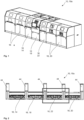
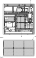
- Fig. 1 shows an embodiment of a system 10 according to the invention in an isometric view.
- the system 10 can be designed as a soldering system 10a and include several modules 16.
- the system 10 comprises at least five modules 16, whereby the first and last module 16 can each be further divided.
- the middle three modules 16 form a preheating module 14, a soldering or sintering module 18 and a soft cooling module 22.
- the soft cooling module is arranged between the soldering or sintering module 18 and the cooling module 20.
- the cooling module 20 forms the last module 16 of the system 10 in the embodiment shown.
- a discharge module can be connected downstream of the cooling module 20.
- the module 16 on the left in the illustration can therefore be designed as a loading module.
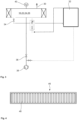
- Fig. 2 a sectional view of a further embodiment of a system 10 according to the invention is shown.
- the vacuum flat slides 44 can be seen between the individual modules 16.
- the housing is made of Fig. 1 not shown.
- This embodiment shows four modules 16, a preheating module 14, a soldering or sintering module 18, a soft cooling module 22 and a cooling module 20.
- the modules 16 are arranged one after the other in the order described.
- the soft cooling module 16 is spatially separated from the soldering or sintering module 18 and the cooling module 20 with a vacuum flat slide 44.
- a heating plate can be arranged in the soft cooling module 16, wherein the heating plate can be cooled from below with cold gas, in particular nitrogen. This allows the electronic assemblies to cool down to just below the solder solidification temperature.
- Fig. 3 shows a circuit diagram of an embodiment of a system 10 according to the invention.
- the soft cooling module 22 can be designed as a pressure chamber 24 or as a vacuum chamber 26.
- a pressure relief valve 30 is arranged on the soft cooling module 22.
- the soft cooling module 22 is connected to a backing pump 38 via an evacuation valve 36.
- a gas collecting container 32 is provided for flushing the electronic assemblies and is connected to the soft cooling module 22 via an inlet valve 28.
- the gas collecting container can, for example, collect the gas, in particular nitrogen, with which the electronic assemblies in the soft cooling module 22 were flushed.
- the gas is cleaned before, after or in the gas collecting container 2 in order to then be fed back to the soft cooling module 22 via a supply line. This means the gas can be reused.
- the soft cooling module 22 includes a quick vent valve 34. The structure described allows an overpressure, a negative pressure or a vacuum in the soft cooling module 22 to be controlled.
- Fig. 4 shows an embodiment of a cold trap 46.
- the cold trap 46 can be arranged in the process chamber of the soft cooling module 22.
- the cold trap 46 has ribs 46 in order to increase a cooling surface and to enable condensate to drip off.
- the cold trap 46 can have a drip tray (not shown) which is set up to collect the condensate.
- the cold trap 46 can also serve as a gas cooler to protect the downstream valves and the downstream pump technology.
- Fig. 5 is a circuit diagram of a further embodiment of an inventive Appendix 10 shown.
- a further pressure control valve 42 is arranged on the soft cooling module 22.
- this can have a connection to the exhaust air.
- an overpressure can be generated in the soft cooling module 22, whereby the overpressure can be, for example, less than 0.5 bar in order to avoid proof according to the Pressure Equipment Directive.
- the soft cooling module 22 can be designed according to the Pressure Equipment Directive and have an overpressure of, for example, 3 bar or more. Controlled temperature control down to just below the solder solidification temperature can take place via a heating and/or cooling device in the soft cooling module 22. In this way, contamination in the solder can be avoided, since these remain in the soft cooling module 22 before they have completely cooled down to room temperature in the downstream cooling module 20 and thus do not accumulate on the electronic assemblies.
- a flushing gas is therefore advantageously used in the soft cooling module 22, with which the contaminants are removed or flushed out directly from the soft cooling module 22.
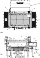
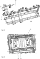
- Fig. 6 shows a top view of a process chamber 52.
- the process chamber 52 is preferably designed as a gas-tight sealable process chamber 52 and arranged in a module 16, which is designed as a soldering module 18.
- several electronic assemblies are arranged on a workpiece carrier 56.
- a heat source 50 shown in Fig. 7
- a cold trap 46 arranged in the process chamber 52.
- the process chamber 52 is a vacuum process chamber.
- a specific process atmosphere can be provided in the process chamber 52 by the heat source 50 and the cold trap 46.
- flows in the process atmosphere can arise solely through convection, which is generated by a temperature difference between the cold trap 46 and the heat source 50.
- Fig. 7 shows a sectional view of the process chamber 52 Fig. 6 .
- the heat source 50 is shown on the underside of the process chamber 52.
- the heat source 50 is therefore preferably located below the workpiece carrier 56.
- An additional heat source (not shown) can be arranged for additional heating of the process chamber 52.
- the cold area 72 protrudes as far as possible into the process chamber 52.
- the cold trap 46 results in less contamination of the modules 16 during the soldering process. This is achieved by collecting the condensate from the soldering paste and specifically directing it out of the system.
- Fig. 8 shows another view of the process chamber 52 Fig. 6 .
- the surfaces on which the remaining condensate evaporates are represented by the temperature control zones 76.
- targeted use of the vapor pressure of solvent can be exploited. Some solvents precipitate on the temperature control zones 76 because the vapor pressure is higher than at 100 ° C with a pressure of 950 bar.
- the residues of the solvent also evaporate for condensation on the cold surfaces, ie in the cold areas 72, of the cold trap 46 and are therefore specifically collected.
- the temperature control zone 76 the temperatures can be at 100 °C.
- the temperatures can be 150 ° C to 300 ° C.
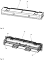
- Fig. 9 shows a cold trap 46 with cooling fins 48.
- the cooling fins 48 can be arranged on the inner wall of the process chamber 52 and serve to increase the cooling surface. Furthermore, the cooling fins 48 can improve the dripping of the condensate.
- the illustration shows a view from the interior of the process chamber 52, with a workpiece carrier 56 being arranged on the floor of the process chamber 52.
- Fig. 10 shows a further embodiment of a cold trap 46 with cooling fins 48. Below the cooling fins 48, a collecting device 64 can be seen; this is designed to collect the condensate generated on the cold trap 46.
- Fig. 11 shows a side view of another cold trap 46.
- the direction of the dripping or the flow direction of the condensate is shown by the arrow directions.
- the collecting device 64 can be designed, for example, as a drip tray.
- the collected condensate flows via the collecting device 64 towards a collecting container 82. Continuous evacuation can be supported via a vacuum pump line.
- the condensate contains in particular solvents, unwanted deposits and/or contamination.
- Fig. 12 shows a possible cooling circuit in a cold trap 46, shown by the direction of the arrow.
- Fig. 13 shows a receiving element 69 for the cold trap 46 Fig. 12 .
- the cold trap 40 can therefore be mounted interchangeably.
- the cold trap 46 is inserted into the receiving element 69 from behind, in particular via guides 84 which are arranged on two opposite sides of the receiving element 69. In particular, thermal insulation is also arranged on the guides 84.
- the receiving element 69 is mounted directly on the process chamber 52 (not shown). Likewise, the receiving element 69 can form the process chamber 52 itself, whereby the cold trap 46 can be mounted directly on the process chamber 52.
- Fig. 14 shows a collecting device 64 of a cold trap 46.
- the collecting device 64 is designed as a drip tray, with the collected condensate being drained backwards into the receiving element 69 via an opening 65, in this embodiment designed as a slot.
- Fig. 15 shows a top view of a module 16 of the soldering system 10a with robot.
- the module 16 shown can in particular be the one in Fig. 1 represent module 16 shown on the far left, and in particular be designed as a loading station.
- the workpiece carriers 56 in particular are loaded with electronic assemblies 12, and in this embodiment this can be done via a robot arm 78.
- Fig. 16 shows an embodiment of a workpiece carrier 56. This is designed for six electronic assemblies 12. Such a workpiece carrier 56 is used in particular in a process chamber 52 as in Figs. 6 to 9 used.
- Fig. 17 shows a further embodiment of a cold trap 46.
- the cold trap 46 has a collecting device 64, which runs as an inclined plane on the underside of the cold trap 46.
- the collecting device 64 does not have a slot but rather individual openings 65 from which the condensate is drained out of the cold trap 46 and into the receiving element 69 (not shown).
- Fig. 18 shows an embodiment of a receiving element 69 for the cold trap 46 Fig. 17 .
- On the underside of the receiving element 69 several slopes 86 are arranged, via which the condensate can be directed out of the openings 56 of the cold trap 46.
- the condensate runs via the slopes 86 to an opening 88 and is discharged from the receiving element 69 via the opening 88.
- the receiving element 69 has two such openings 88, to which two slopes 86 each lead.
- the receiving element 69 forms a kind of receiving box for the cold trap.
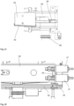
- Fig. 19 shows a side view of the receiving element 69 with cold trap 46 the Figs. 17 and 18 . It can be seen that a pipe 60 is connected to the opening 88, which specifically removes the condensate. In other words, the process chamber 52 is connected via the pipeline 60. An opening of the pipeline 60, which communicates with the opening 88, is provided immediately adjacent to the cold trap 46. A heating sleeve 90 can be arranged around the pipeline 60.
- Some such construction with a receiving element 69 can also be referred to as an evacuation device 62.
- the evacuation device 62 can of course be designed differently than in Fig. 19 shown.
- Fig. 20 shows another view of the execution Fig. 19 . It can be seen that the receiving element 69 has two openings 88 on the underside, each of which is connected via a pipe 60.
- Fig. 21 shows a sectional view of the embodiment Fig. 19 .
- the cold trap 46 with the collecting device 64 in particular in the form of a collecting plate, is inserted into the receiving element 69 from one side.
- the cold trap 46 can be held guided in the receiving element 69 via guides 84.
- Fig. 22 shows a detailed view of the embodiment Fig. 20 .
- a heating element 92 is arranged on the underside of the receiving element 69, the connection 94 of which is also on the right side of the receiving element 69.
- This heating element 92 can, for example, form an additional heat source 54.
- Fig. 23 shows an isometric view of the receiving element 69 with opening element 69a.
- the opening element 69a is pivotally mounted on the receiving element 69.
- Fig. 24 shows a sectional view through a process chamber 52.
- a heating plate 96 is provided, which is provided with soft cooling 98.
- it can have a pivoting lid (not shown) which can be screwed to the process chamber 52. This allows the process chamber 52 be designed to be gas-tight.
- Fig. 25 shows another embodiment of a workpiece carrier 56.
- Fig. 26 shows another view of the embodiment Fig. 25 .
- the heating plate 96 can be seen directly below the receiving elements for the electronic assemblies 12 (not shown).
- the heating plate 96 can be designed as a contact plate in a sandwich construction.
- a cooling process can take place via thermal oil and/or a heating cable.
- Such a sandwich plate can form a controllable and heatable contact plate and can also be referred to as a soft cooling plate.
- heating conductors 98 inserted in a meandering shape are included in the heating plate 92.
- a thermocouple in particular a substrate thermocouple, may be included, which is, for example, arranged centrally and/or designed to be flexible.
Landscapes
- Engineering & Computer Science (AREA)
- Mechanical Engineering (AREA)
- Physics & Mathematics (AREA)
- Optics & Photonics (AREA)
- Plasma & Fusion (AREA)
- Manufacturing & Machinery (AREA)
- Electric Connection Of Electric Components To Printed Circuits (AREA)
Claims (30)
- Installation de brasage et/ou de frittage (10a) pour relier des composants électroniques (12), avec un dispositif de transport pour le transport des composants électroniques (12) à travers l'installation (10a), comprenant plusieurs modules (16) séparables de manière étanche au gaz pour relier entre eux les composants électroniques (12), sachant qu'au moins un module (16) est conçu sous forme de module de brasage et/ou de frittage (18) et un module (16) sous forme de module de refroidissement (20), caractérisée en ce que l'installation de brasage et/ou de frittage comprend une commande supraordonnée pour commander les modules, sachant qu'est disposé, entre le module de brasage ou de frittage (18) et le module de refroidissement (20), un autre module (16) qui est conçu comme module de refroidissement doux (22) pour refroidir entre une température de processus du module de brasage ou de frittage (18) et une température intermédiaire en dessous d'une température de solidification de la brasure, sachant que dans le module de refroidissement doux (22) est compris un dispositif de chauffage et/ou refroidissement pour la mise en température et le refroidissement commandés des composants électroniques (12) de 500 °C ou en dessous à la température intermédiaire sous la température de solidification de la brasure qui se situe dans une plage comprise entre 220 °C et 150 °C, sachant que dans le module de refroidissement doux (22) est compris un dispositif de rinçage à gaz pour rincer les composants électroniques (12), notamment avec du gaz froid et de préférence, avec de l'azote froid.
- Installation de brasage et/ou de frittage (10a) selon la revendication 1, caractérisée en ce que le module de refroidissement doux (22) est conçu pour fournir une surpression d'une atmosphère de processus de 1 bar, notamment jusqu'à 4,5 bar.
- Installation de brasage et/ou de frittage (10a) selon la revendication 1 ou 2, caractérisée en ce que le module de refroidissement doux (22) est conçu pour fournir une dépression inférieure à 1 bar, notamment un vide.
- Installation de brasage et/ou de frittage (10a) selon l'une des revendications précédentes, caractérisée en ce que le module de refroidissement doux (22) est conçu sous forme de chambre hyperbare (24) et/ou de chambre à vide (26).
- Installation de brasage et/ou de frittage (10a) selon l'une des revendications précédentes, caractérisée en ce que le dispositif de chauffage et/ou de refroidissement a la forme d'une plaque de contact chauffable et/ou refroidissable.
- Installation de brasage et/ou de frittage (10a) selon la revendication 5, caractérisée en ce que la plaque de contact est conçue comme plaque de chauffe, et qu'un dispositif de refroidissement est conçu comme dispositif de refroidissement au gaz pour le refroidissement de la plaque de contact au moyen d'un flux de gaz, notamment d'un flux d'azote, depuis un côté de la plaque de chauffe, opposé aux composants électroniques (12).
- Installation de brasage et/ou de frittage (10a) selon la revendication 5 ou 6, caractérisée en ce que la plaque de contact est déplaçable mécaniquement, notamment qu'elle peut être mise en contact et éloignée des composants électroniques (12) et/ou que la plaque de contact comprend un répartiteur de gaz conçu de préférence sous forme de méandre.
- Installation de brasage et/ou de frittage (10a) selon la revendication 1, caractérisée en ce qu'une soupape d'admission (28) pour faire entrer le gaz dans une chambre de processus du module de refroidissement doux (22) est comprise sur le module de refroidissement doux (22).
- Installation de brasage et/ou de frittage (10a) selon la revendication 1 ou 8, caractérisée en ce qu'à l'extérieur d'une chambre de processus du module de refroidissement doux (22) est compris un récupérateur de gaz (32) qui est relié à la soupape d'admission (28) et est conçu pour récupérer le gaz s'écoulant de la chambre de processus du module de refroidissement doux (22).
- Installation de brasage et/ou de frittage (10a) selon l'une des revendications précédentes, caractérisée en ce qu'est compris sur le module de refroidissement doux (22) une soupape de surpression (30) pour contrôler une surpression et/ou une soupape d'échappement rapide (34).
- Installation de brasage et/ou de frittage (10a) selon l'une des revendications précédentes, caractérisée en ce qu'une surpression de 4 à 6 bar est présente dans le module de refroidissement doux (22).
- Installation de brasage et/ou de frittage (10a) selon l'une des revendications précédentes, caractérisée en ce qu'a lieu, dans le module de refroidissement (20), un refroidissement d'une température en dessous de la température de solidification de la brasure à la température ambiante, notamment d'une température inférieure à 200 °C à la température ambiante.
- Installation de brasage et/ou de frittage (10a) selon l'une des revendications précédentes, caractérisée en ce qu'une pression normale ou une dépression, notamment un vide, est présente dans le module de refroidissement (20).
- Installation de brasage et/ou de frittage (10a) selon l'une des revendications précédentes, caractérisée en ce qu'est compris un autre module (16) connecté en amont du module de brasage ou de frittage (18) qui est conçu sous forme de module de préchauffage (14).
- Installation de brasage et/ou de frittage (10a) selon l'une des revendications précédentes, caractérisée en ce qu'est compris un piège cryogénique (46) dans la chambre de processus du module de refroidissement doux (22), notamment comme refroidisseur de gaz dans la voie de sortie de gaz de la chambre de processus.
- Installation de brasage et/ou de frittage (10a) selon l'une des revendications précédentes, caractérisée en ce que la séparation des modules (16) séparables de manière étanche au gaz a lieu au moyen de robinets plats à vide (44), sachant qu'une étanchéité des robinets plats à vide (44) augmente en cas de hausse de la pression et/ou qu'un équilibrage de pression a lieu via les robinets à vide (44) en cas de pression trop élevée.
- Installation de brasage et/ou de frittage (10a) selon la revendication 1, caractérisée en ce que dans un module (16) qui est conçu notamment sous forme de module de brasage ou de frittage (18) ou sous forme de module de refroidissement doux (22), est disposée dans une chambre de processus (52) verrouillable de manière étanche au gaz au moins une source de chaleur (50) pouvant être mise en contact avec les composants électroniques (12), pour chauffer les composants électroniques (12) et au moins un piège cryogénique (46) qui présente en service une température de surface inférieure à une température de service de la source de chaleur (50).
- Installation de brasage et/ou de frittage (10a) selon la revendication 17, caractérisée en ce que dans la chambre de processus (52) est fournie une atmosphère de processus spécifique, sachant que le piège cryogénique (46) et la source de chaleur (50) sont disposés l'un par rapport à l'autre de sorte qu'au moins pendant une phase de service spécifique existent des flux dans l'atmosphère de processus rien qu'en raison de convection générée par une différence de température entre le piège cryogénique (46) et la source de chaleur (50).
- Installation de brasage et/ou de frittage (10a) selon la revendication 17 ou 18, caractérisée en ce que la température de surface du piège cryogénique (46) est comprise entre -196 °C (77 K) et 150 °C, notamment entre 16 °C et 25 °C, et sachant que de préférence une température de surface cascadable du piège cryogénique (46) peut être fournie.
- Installation de brasage et/ou de frittage (10a) selon l'une des revendications 17 à 19, caractérisée en ce qu'au moins une source de chaleur supplémentaire (54) est prévue pour chauffer la chambre de processus (52).
- Installation de brasage et/ou de frittage (10a) selon l'une des revendications 17 à 20, caractérisée en ce que la température de service de la source de chaleur (50) et/ou de la source de chaleur supplémentaire (54) est comprise entre 150°C et 400 °C ou, de préférence, entre 200 °C et 300 °C.
- Installation de brasage et/ou de frittage (10a) selon l'une des revendications 17 à 21, caractérisée en ce qu'au moins un composant, notamment une pluralité de composants (12), sont disposés sur un porte-pièces (56) et sont éloignés au moins temporairement de celui-ci dans le sens du piège cryogénique (46) de sorte que l'écart entre les composants (12) et le piège cryogénique (46) est inférieur à l'écart entre le porte-pièces (56) et le piège cryogénique (46).
- Installation de brasage et/ou de frittage (10a) selon l'une des revendications 17 à 22, caractérisée en ce qu'au moins une zone partielle de la chambre de processus (52), notamment au moins une surface de paroi de la chambre de processus (52) et/ou une surface d'un dispositif de transport (58) disposé dans la chambre de processus (56), qui est prévu pour amener et/ou retirer les composants, est conçue comme zone de mise en température, sachant que la zone de mise en température en service présente une température comprise entre la température de surface du piège cryogénique (46) et la température de service de la source de chaleur (50), sachant que la température de la zone de mise en température est comprise de préférence entre 50 °C et 150 °C, notamment entre 80 °C et 120 °C.
- Installation de brasage et/ou de frittage (10a) selon l'une des revendications 17 à 23, caractérisée en ce que la chambre de processus (52) est reliée ou reliable à un dispositif d'évacuation (62) via une conduite (60), sachant qu'une embouchure de la conduite (60) dans la chambre de processus (52) est prévue directement au voisinage du piège cryogénique (46).
- Installation de brasage et/ou de frittage (10a) selon l'une des revendications 17 à 24, caractérisée en ce que le piège cryogénique (46) présente plusieurs ailettes de refroidissement (48) s'étendant de préférence dans le sens vertical.
- Installation de brasage et/ou de frittage (10a) selon l'une des revendications 17 à 25, caractérisée en ce que sous le piège cryogénique (46) est prévu un dispositif de récupération (64) pour récupérer le condensat produit sur le piège cryogénique (46).
- Installation de brasage et/ou de frittage (10a) selon la revendication 22, caractérisée en ce que la source de chaleur (50), et/ou le porte-pièces (56) avec les composants (12) sont réglables en direction du piège cryogénique (46), l'un par rapport à l'autre concernant leur écart.
- Installation de brasage et/ou de frittage (10a) selon la revendication 22, caractérisée en ce que le porte-pièces (56) est chauffable séparément.
- Installation de brasage et/ou de frittage (10a) selon l'une des revendications 17 à 28, caractérisée en ce qu'une pompe à vide d'extraction régulée en vitesse (66) avec un séparateur de liquide (68) est prévue pour générer une dépression dans la chambre de processus (52).
- Installation de brasage et/ou de frittage (10a) selon l'une des revendications 17 à 29, caractérisée en ce que pour amener et/ou retirer les composants (12) est prévu au moins un robinet plat à vide chauffable, notamment des robinets plats à vide chauffables sur les deux côtés opposés de la chambre de processus (52).
Applications Claiming Priority (3)
| Application Number | Priority Date | Filing Date | Title |
|---|---|---|---|
| DE102020113320 | 2020-05-15 | ||
| DE102020119527 | 2020-07-23 | ||
| PCT/EP2021/062871 WO2021229073A1 (fr) | 2020-05-15 | 2021-05-14 | Installation pour relier des composants électroniques |
Publications (3)
| Publication Number | Publication Date |
|---|---|
| EP4149708A1 EP4149708A1 (fr) | 2023-03-22 |
| EP4149708C0 EP4149708C0 (fr) | 2024-01-10 |
| EP4149708B1 true EP4149708B1 (fr) | 2024-01-10 |
Family
ID=76076317
Family Applications (1)
| Application Number | Title | Priority Date | Filing Date |
|---|---|---|---|
| EP21727397.8A Active EP4149708B1 (fr) | 2020-05-15 | 2021-05-14 | Installation pour relier des composants électroniques |
Country Status (8)
| Country | Link |
|---|---|
| US (1) | US11998999B2 (fr) |
| EP (1) | EP4149708B1 (fr) |
| JP (1) | JP7486234B2 (fr) |
| KR (1) | KR102572094B1 (fr) |
| CN (1) | CN115605310A (fr) |
| HU (1) | HUE066004T2 (fr) |
| MX (1) | MX2022014325A (fr) |
| WO (1) | WO2021229073A1 (fr) |
Families Citing this family (8)
| Publication number | Priority date | Publication date | Assignee | Title |
|---|---|---|---|---|
| US11633797B2 (en) * | 2019-11-15 | 2023-04-25 | General Electric Company | Braze joints for a component and methods of forming the same |
| EP4032648A1 (fr) * | 2021-01-25 | 2022-07-27 | Infineon Technologies AG | Agencement pour la formation d'une connexion |
| TWI874823B (zh) * | 2021-10-14 | 2025-03-01 | 德商平克塞莫系統有限公司 | 多功能設備和衝壓工具 |
| CN119016851A (zh) * | 2024-02-21 | 2024-11-26 | 安泊智汇半导体设备(上海)有限公司 | 一种真空感应加热焊接设备 |
| EP4681851A1 (fr) * | 2024-07-17 | 2026-01-21 | Illinois Tool Works Inc. | Four de brasage par refusion amélioré |
| CN118635617B (zh) * | 2024-08-15 | 2024-11-08 | 深圳中宝新材科技有限公司 | 基于键合银丝的电子元器件焊接装置及其使用方法 |
| TWI908495B (zh) * | 2024-11-25 | 2025-12-11 | 國立屏東科技大學 | 紅外線回焊裝置之溫度控制系統 |
| CN119839554B (zh) * | 2025-03-07 | 2025-10-03 | 深圳市思立康技术有限公司 | 一种半导体封装用的甲酸真空焊接设备 |
Citations (2)
| Publication number | Priority date | Publication date | Assignee | Title |
|---|---|---|---|---|
| DE3843191C2 (de) * | 1988-12-22 | 1994-09-15 | Broadcast Television Syst | Vorrichtung zum Löten |
| EP0427020B1 (fr) * | 1989-11-06 | 1996-04-17 | Herbert Streckfuss Maschinenbau- Und Verwaltungs-Kg | Méthode et procédé de traitement de partenaires de joints de brasage |
Family Cites Families (11)
| Publication number | Priority date | Publication date | Assignee | Title |
|---|---|---|---|---|
| JPH0714353Y2 (ja) | 1988-07-08 | 1995-04-05 | 中外炉工業株式会社 | ローラハース型熱処理炉 |
| DE4024181C1 (en) * | 1990-07-30 | 1992-02-13 | Siemens Nixdorf Informationssysteme Ag, 4790 Paderborn, De | Vapour phase soldering installation - has valve in by=pass opening in dependence on preset temp. of sec. medium in soldering tank |
| JP3924668B2 (ja) * | 1999-03-01 | 2007-06-06 | 光洋サーモシステム株式会社 | リフロー装置 |
| DE19953654A1 (de) * | 1999-11-08 | 2001-05-23 | Pink Gmbh Vakuumtechnik | Verfahren und Vorrichtung zur Herstellung einer Lotverbindung |
| DE10237494B4 (de) | 2002-08-16 | 2005-08-18 | IBL-Löttechnik GmbH | Verfahren und Vorrichtung für das Löten in der Dampfphase |
| DE102007005345B4 (de) | 2007-02-02 | 2014-06-18 | Seho Systemtechnik Gmbh | Verfahren zum Reflow-Löten sowie Vorrichtung zur Durchführung des Verfahrens |
| JP5247060B2 (ja) * | 2007-04-27 | 2013-07-24 | 株式会社タムラ製作所 | リフロー装置およびフラックスの除去方法 |
| DE102008009510B3 (de) | 2008-02-15 | 2009-07-16 | Danfoss Silicon Power Gmbh | Verfahren zum Niedertemperatur-Drucksintern |
| DE102008021240B4 (de) | 2008-04-28 | 2012-11-22 | Ersa Gmbh | Vorrichtung zur thermischen Behandlung von Werkstücken und Verfahren zur Bestimmung der thermischen Prozessstabilität in einer solchen Vorrichtung |
| DE202011107022U1 (de) | 2011-10-21 | 2012-04-05 | Asscon Systemtechnik-Elektronik Gmbh | Vorrichtung zum Löten |
| DE102014106631B4 (de) | 2013-05-10 | 2021-12-02 | Seho Systemtechnik Gmbh | Vorrichtung und Verfahren zum Herstellen von Lötverbindungen |
-
2021
- 2021-05-14 JP JP2022569040A patent/JP7486234B2/ja active Active
- 2021-05-14 WO PCT/EP2021/062871 patent/WO2021229073A1/fr not_active Ceased
- 2021-05-14 MX MX2022014325A patent/MX2022014325A/es unknown
- 2021-05-14 US US17/924,921 patent/US11998999B2/en active Active
- 2021-05-14 KR KR1020227040317A patent/KR102572094B1/ko active Active
- 2021-05-14 HU HUE21727397A patent/HUE066004T2/hu unknown
- 2021-05-14 CN CN202180035333.6A patent/CN115605310A/zh active Pending
- 2021-05-14 EP EP21727397.8A patent/EP4149708B1/fr active Active
Patent Citations (2)
| Publication number | Priority date | Publication date | Assignee | Title |
|---|---|---|---|---|
| DE3843191C2 (de) * | 1988-12-22 | 1994-09-15 | Broadcast Television Syst | Vorrichtung zum Löten |
| EP0427020B1 (fr) * | 1989-11-06 | 1996-04-17 | Herbert Streckfuss Maschinenbau- Und Verwaltungs-Kg | Méthode et procédé de traitement de partenaires de joints de brasage |
Also Published As
| Publication number | Publication date |
|---|---|
| EP4149708A1 (fr) | 2023-03-22 |
| US11998999B2 (en) | 2024-06-04 |
| HUE066004T2 (hu) | 2024-06-28 |
| EP4149708C0 (fr) | 2024-01-10 |
| US20230191518A1 (en) | 2023-06-22 |
| JP2023518120A (ja) | 2023-04-27 |
| KR20220158868A (ko) | 2022-12-01 |
| JP7486234B2 (ja) | 2024-05-17 |
| KR102572094B1 (ko) | 2023-08-30 |
| MX2022014325A (es) | 2022-12-08 |
| CN115605310A (zh) | 2023-01-13 |
| WO2021229073A1 (fr) | 2021-11-18 |
Similar Documents
| Publication | Publication Date | Title |
|---|---|---|
| EP4149708B1 (fr) | Installation pour relier des composants électroniques | |
| EP2026927B1 (fr) | Procédé et dispositif de traitement thermique, en particulier une jonction par soudure | |
| DE19982566B4 (de) | Einrichtung und Verfahren zum Bearbeiten eines Substrats | |
| DE60310291T2 (de) | Verfahren und Vorrichtung zur Gasphasenbeschichtung | |
| DE102014106631B4 (de) | Vorrichtung und Verfahren zum Herstellen von Lötverbindungen | |
| EP3618993B1 (fr) | Procédé de réalisation d'une liaison brasée entre des éléments par utilisation d'un matériau adhésif pour la liaison provisoire entre ces éléments | |
| DE102008022784A1 (de) | Vorrichtung und Verfahren zum Tempern von Gegenständen in einer Behandlungskammer | |
| DE102014114093A1 (de) | Verfahren und Vorrichtung zum Niedertemperatur-Drucksintern | |
| DE19911887C1 (de) | Verfahren zum Reflow-Löten in einer Dampfphasenvakuumlötanlage | |
| DE102016102162A1 (de) | Sintervorrichtung | |
| EP2870625B1 (fr) | Installation et procédé destinés à traiter des substrats | |
| EP3618994B1 (fr) | Procédé de réalisation d'une liaison brasée par utilisation de plaques de base et de pression et d'un dispositif de butée | |
| EP2609619B1 (fr) | Dispositif et procédé de traitement de tranches | |
| DE102006034600A1 (de) | Verfahren zur Herstellung einer Lötverbindung | |
| DE2244913C2 (de) | Verfahren und Vorrichtung zur Wärmebehandlung von Bandstahl | |
| EP2768625B1 (fr) | Dispositif et procédé de soudage | |
| DE4041270A1 (de) | Verfahren und vorrichtung zur verarbeitung von elektronischen flachbaugruppen, insbesondere mit bauelementen bestueckten leiterplatten | |
| WO2013178260A1 (fr) | Dispositif et procédé pour relier par métallisation des substrats | |
| DE69603666T2 (de) | Verfahren zum Trockenfluxen von metallischen Fläschen vor dem Löten mit einer Atmosphäre die Wasserdampf enthält | |
| WO2003031372A2 (fr) | Procede de production de materiaux composites metal-ceramique, notamment de substrats metal-ceramique, et materiau composite metal-ceramique, notamment substrat metal-ceramique produit grace a ce procede | |
| EP2592173A2 (fr) | Agencement et procédé de réalisation d'un procédé ALD à basse température | |
| EP1979930A1 (fr) | Dispositif de dégazage d un substrat en forme de disque | |
| CH671350A5 (fr) |
Legal Events
| Date | Code | Title | Description |
|---|---|---|---|
| STAA | Information on the status of an ep patent application or granted ep patent |
Free format text: STATUS: UNKNOWN |
|
| STAA | Information on the status of an ep patent application or granted ep patent |
Free format text: STATUS: THE INTERNATIONAL PUBLICATION HAS BEEN MADE |
|
| PUAI | Public reference made under article 153(3) epc to a published international application that has entered the european phase |
Free format text: ORIGINAL CODE: 0009012 |
|
| STAA | Information on the status of an ep patent application or granted ep patent |
Free format text: STATUS: REQUEST FOR EXAMINATION WAS MADE |
|
| 17P | Request for examination filed |
Effective date: 20221215 |
|
| AK | Designated contracting states |
Kind code of ref document: A1 Designated state(s): AL AT BE BG CH CY CZ DE DK EE ES FI FR GB GR HR HU IE IS IT LI LT LU LV MC MK MT NL NO PL PT RO RS SE SI SK SM TR |
|
| P01 | Opt-out of the competence of the unified patent court (upc) registered |
Effective date: 20230602 |
|
| DAV | Request for validation of the european patent (deleted) | ||
| DAX | Request for extension of the european patent (deleted) | ||
| GRAP | Despatch of communication of intention to grant a patent |
Free format text: ORIGINAL CODE: EPIDOSNIGR1 |
|
| STAA | Information on the status of an ep patent application or granted ep patent |
Free format text: STATUS: GRANT OF PATENT IS INTENDED |
|
| INTG | Intention to grant announced |
Effective date: 20231006 |
|
| GRAS | Grant fee paid |
Free format text: ORIGINAL CODE: EPIDOSNIGR3 |
|
| GRAA | (expected) grant |
Free format text: ORIGINAL CODE: 0009210 |
|
| STAA | Information on the status of an ep patent application or granted ep patent |
Free format text: STATUS: THE PATENT HAS BEEN GRANTED |
|
| AK | Designated contracting states |
Kind code of ref document: B1 Designated state(s): AL AT BE BG CH CY CZ DE DK EE ES FI FR GB GR HR HU IE IS IT LI LT LU LV MC MK MT NL NO PL PT RO RS SE SI SK SM TR |
|
| REG | Reference to a national code |
Ref country code: GB Ref legal event code: FG4D Free format text: NOT ENGLISH |
|
| REG | Reference to a national code |
Ref country code: CH Ref legal event code: EP |
|
| REG | Reference to a national code |
Ref country code: DE Ref legal event code: R096 Ref document number: 502021002450 Country of ref document: DE |
|
| REG | Reference to a national code |
Ref country code: IE Ref legal event code: FG4D Free format text: LANGUAGE OF EP DOCUMENT: GERMAN |
|
| U01 | Request for unitary effect filed |
Effective date: 20240124 |
|
| U07 | Unitary effect registered |
Designated state(s): AT BE BG DE DK EE FI FR IT LT LU LV MT NL PT SE SI Effective date: 20240130 |
|
| P04 | Withdrawal of opt-out of the competence of the unified patent court (upc) registered |
Effective date: 20240126 |
|
| U20 | Renewal fee for the european patent with unitary effect paid |
Year of fee payment: 4 Effective date: 20240425 |
|
| REG | Reference to a national code |
Ref country code: HU Ref legal event code: AG4A Ref document number: E066004 Country of ref document: HU |
|
| PG25 | Lapsed in a contracting state [announced via postgrant information from national office to epo] |
Ref country code: IS Free format text: LAPSE BECAUSE OF FAILURE TO SUBMIT A TRANSLATION OF THE DESCRIPTION OR TO PAY THE FEE WITHIN THE PRESCRIBED TIME-LIMIT Effective date: 20240510 |
|
| PG25 | Lapsed in a contracting state [announced via postgrant information from national office to epo] |
Ref country code: GR Free format text: LAPSE BECAUSE OF FAILURE TO SUBMIT A TRANSLATION OF THE DESCRIPTION OR TO PAY THE FEE WITHIN THE PRESCRIBED TIME-LIMIT Effective date: 20240411 |
|
| PG25 | Lapsed in a contracting state [announced via postgrant information from national office to epo] |
Ref country code: HR Free format text: LAPSE BECAUSE OF FAILURE TO SUBMIT A TRANSLATION OF THE DESCRIPTION OR TO PAY THE FEE WITHIN THE PRESCRIBED TIME-LIMIT Effective date: 20240110 Ref country code: RS Free format text: LAPSE BECAUSE OF FAILURE TO SUBMIT A TRANSLATION OF THE DESCRIPTION OR TO PAY THE FEE WITHIN THE PRESCRIBED TIME-LIMIT Effective date: 20240410 |
|
| PG25 | Lapsed in a contracting state [announced via postgrant information from national office to epo] |
Ref country code: ES Free format text: LAPSE BECAUSE OF FAILURE TO SUBMIT A TRANSLATION OF THE DESCRIPTION OR TO PAY THE FEE WITHIN THE PRESCRIBED TIME-LIMIT Effective date: 20240110 |
|
| PG25 | Lapsed in a contracting state [announced via postgrant information from national office to epo] |
Ref country code: RS Free format text: LAPSE BECAUSE OF FAILURE TO SUBMIT A TRANSLATION OF THE DESCRIPTION OR TO PAY THE FEE WITHIN THE PRESCRIBED TIME-LIMIT Effective date: 20240410 Ref country code: NO Free format text: LAPSE BECAUSE OF FAILURE TO SUBMIT A TRANSLATION OF THE DESCRIPTION OR TO PAY THE FEE WITHIN THE PRESCRIBED TIME-LIMIT Effective date: 20240410 Ref country code: IS Free format text: LAPSE BECAUSE OF FAILURE TO SUBMIT A TRANSLATION OF THE DESCRIPTION OR TO PAY THE FEE WITHIN THE PRESCRIBED TIME-LIMIT Effective date: 20240510 Ref country code: HR Free format text: LAPSE BECAUSE OF FAILURE TO SUBMIT A TRANSLATION OF THE DESCRIPTION OR TO PAY THE FEE WITHIN THE PRESCRIBED TIME-LIMIT Effective date: 20240110 Ref country code: GR Free format text: LAPSE BECAUSE OF FAILURE TO SUBMIT A TRANSLATION OF THE DESCRIPTION OR TO PAY THE FEE WITHIN THE PRESCRIBED TIME-LIMIT Effective date: 20240411 Ref country code: ES Free format text: LAPSE BECAUSE OF FAILURE TO SUBMIT A TRANSLATION OF THE DESCRIPTION OR TO PAY THE FEE WITHIN THE PRESCRIBED TIME-LIMIT Effective date: 20240110 |
|
| PG25 | Lapsed in a contracting state [announced via postgrant information from national office to epo] |
Ref country code: PL Free format text: LAPSE BECAUSE OF FAILURE TO SUBMIT A TRANSLATION OF THE DESCRIPTION OR TO PAY THE FEE WITHIN THE PRESCRIBED TIME-LIMIT Effective date: 20240110 |
|
| PG25 | Lapsed in a contracting state [announced via postgrant information from national office to epo] |
Ref country code: PL Free format text: LAPSE BECAUSE OF FAILURE TO SUBMIT A TRANSLATION OF THE DESCRIPTION OR TO PAY THE FEE WITHIN THE PRESCRIBED TIME-LIMIT Effective date: 20240110 |
|
| REG | Reference to a national code |
Ref country code: DE Ref legal event code: R097 Ref document number: 502021002450 Country of ref document: DE |
|
| PG25 | Lapsed in a contracting state [announced via postgrant information from national office to epo] |
Ref country code: SM Free format text: LAPSE BECAUSE OF FAILURE TO SUBMIT A TRANSLATION OF THE DESCRIPTION OR TO PAY THE FEE WITHIN THE PRESCRIBED TIME-LIMIT Effective date: 20240110 |
|
| PG25 | Lapsed in a contracting state [announced via postgrant information from national office to epo] |
Ref country code: CZ Free format text: LAPSE BECAUSE OF FAILURE TO SUBMIT A TRANSLATION OF THE DESCRIPTION OR TO PAY THE FEE WITHIN THE PRESCRIBED TIME-LIMIT Effective date: 20240110 |
|
| PG25 | Lapsed in a contracting state [announced via postgrant information from national office to epo] |
Ref country code: SK Free format text: LAPSE BECAUSE OF FAILURE TO SUBMIT A TRANSLATION OF THE DESCRIPTION OR TO PAY THE FEE WITHIN THE PRESCRIBED TIME-LIMIT Effective date: 20240110 |
|
| PG25 | Lapsed in a contracting state [announced via postgrant information from national office to epo] |
Ref country code: SM Free format text: LAPSE BECAUSE OF FAILURE TO SUBMIT A TRANSLATION OF THE DESCRIPTION OR TO PAY THE FEE WITHIN THE PRESCRIBED TIME-LIMIT Effective date: 20240110 Ref country code: SK Free format text: LAPSE BECAUSE OF FAILURE TO SUBMIT A TRANSLATION OF THE DESCRIPTION OR TO PAY THE FEE WITHIN THE PRESCRIBED TIME-LIMIT Effective date: 20240110 Ref country code: CZ Free format text: LAPSE BECAUSE OF FAILURE TO SUBMIT A TRANSLATION OF THE DESCRIPTION OR TO PAY THE FEE WITHIN THE PRESCRIBED TIME-LIMIT Effective date: 20240110 |
|
| PLBE | No opposition filed within time limit |
Free format text: ORIGINAL CODE: 0009261 |
|
| STAA | Information on the status of an ep patent application or granted ep patent |
Free format text: STATUS: NO OPPOSITION FILED WITHIN TIME LIMIT |
|
| 26N | No opposition filed |
Effective date: 20241011 |
|
| P05 | Withdrawal of opt-out of the competence of the unified patent court (upc) changed |
Free format text: CASE NUMBER: APP_4314/2024 Effective date: 20240130 |
|
| PG25 | Lapsed in a contracting state [announced via postgrant information from national office to epo] |
Ref country code: MC Free format text: LAPSE BECAUSE OF FAILURE TO SUBMIT A TRANSLATION OF THE DESCRIPTION OR TO PAY THE FEE WITHIN THE PRESCRIBED TIME-LIMIT Effective date: 20240110 |
|
| PG25 | Lapsed in a contracting state [announced via postgrant information from national office to epo] |
Ref country code: MC Free format text: LAPSE BECAUSE OF FAILURE TO SUBMIT A TRANSLATION OF THE DESCRIPTION OR TO PAY THE FEE WITHIN THE PRESCRIBED TIME-LIMIT Effective date: 20240110 |
|
| PG25 | Lapsed in a contracting state [announced via postgrant information from national office to epo] |
Ref country code: IE Free format text: LAPSE BECAUSE OF NON-PAYMENT OF DUE FEES Effective date: 20240514 |
|
| U20 | Renewal fee for the european patent with unitary effect paid |
Year of fee payment: 5 Effective date: 20250425 |
|
| PGFP | Annual fee paid to national office [announced via postgrant information from national office to epo] |
Ref country code: GB Payment date: 20250522 Year of fee payment: 5 |
|
| PGFP | Annual fee paid to national office [announced via postgrant information from national office to epo] |
Ref country code: HU Payment date: 20250512 Year of fee payment: 5 |
|
| PGFP | Annual fee paid to national office [announced via postgrant information from national office to epo] |
Ref country code: CH Payment date: 20250601 Year of fee payment: 5 |
|
| PGFP | Annual fee paid to national office [announced via postgrant information from national office to epo] |
Ref country code: RO Payment date: 20250430 Year of fee payment: 5 |
|
| PG25 | Lapsed in a contracting state [announced via postgrant information from national office to epo] |
Ref country code: CY Free format text: LAPSE BECAUSE OF FAILURE TO SUBMIT A TRANSLATION OF THE DESCRIPTION OR TO PAY THE FEE WITHIN THE PRESCRIBED TIME-LIMIT; INVALID AB INITIO Effective date: 20210514 |