EP4149721B1 - Unité motrice pour collier de pression - Google Patents
Unité motrice pour collier de pression Download PDFInfo
- Publication number
- EP4149721B1 EP4149721B1 EP21723665.2A EP21723665A EP4149721B1 EP 4149721 B1 EP4149721 B1 EP 4149721B1 EP 21723665 A EP21723665 A EP 21723665A EP 4149721 B1 EP4149721 B1 EP 4149721B1
- Authority
- EP
- European Patent Office
- Prior art keywords
- press
- drive unit
- marking
- connecting element
- pressing
- Prior art date
- Legal status (The legal status is an assumption and is not a legal conclusion. Google has not performed a legal analysis and makes no representation as to the accuracy of the status listed.)
- Active
Links
Images

Classifications
-
- B—PERFORMING OPERATIONS; TRANSPORTING
- B25—HAND TOOLS; PORTABLE POWER-DRIVEN TOOLS; MANIPULATORS
- B25B—TOOLS OR BENCH DEVICES NOT OTHERWISE PROVIDED FOR, FOR FASTENING, CONNECTING, DISENGAGING, OR HOLDING
- B25B27/00—Hand tools, specially adapted for fitting together or separating parts or objects whether or not involving some deformation, not otherwise provided for
- B25B27/02—Hand tools, specially adapted for fitting together or separating parts or objects whether or not involving some deformation, not otherwise provided for for connecting objects by press fit or detaching same
- B25B27/10—Hand tools, specially adapted for fitting together or separating parts or objects whether or not involving some deformation, not otherwise provided for for connecting objects by press fit or detaching same inserting fittings into hoses
-
- B—PERFORMING OPERATIONS; TRANSPORTING
- B21—MECHANICAL METAL-WORKING WITHOUT ESSENTIALLY REMOVING MATERIAL; PUNCHING METAL
- B21D—WORKING OR PROCESSING OF SHEET METAL OR METAL TUBES, RODS OR PROFILES WITHOUT ESSENTIALLY REMOVING MATERIAL; PUNCHING METAL
- B21D39/00—Application of procedures in order to connect objects or parts, e.g. coating with sheet metal otherwise than by plating; Tube expanders
- B21D39/04—Application of procedures in order to connect objects or parts, e.g. coating with sheet metal otherwise than by plating; Tube expanders of tubes with tubes; of tubes with rods
- B21D39/048—Application of procedures in order to connect objects or parts, e.g. coating with sheet metal otherwise than by plating; Tube expanders of tubes with tubes; of tubes with rods using presses for radially crimping tubular elements
Definitions
- the present invention relates to a drive unit for use with a press loop for pressing two workpieces and to a system with such a drive unit and such a press loop.
- a press loop is known in which several press elements are connected to one another in an articulated and chain-like manner by means of bolts.
- Each press element has several press loop segments arranged in parallel, which extend from one bolt to the next bolt.
- the press loop segments of successive press elements of the press loop are arranged offset. The force is transferred from one press element to the next via the press loop segments.
- a connecting bolt is provided with each of the first pressing element and the last pressing element.
- a drive unit in particular an electro-hydraulic drive unit, can be connected to this connecting bolt.
- the drive unit has a pressing tongs with two jaws.
- the jaws of the pressing tongs can be moved towards each other by means of a drive of the drive unit.
- the jaws each have a recess for receiving a connecting bolt, so that the movement of the jaws is transferred to the pressing loop.
- the pressing loop must be connected by the user himself to the pressing tongs of the drive unit, in particular by inserting the connecting bolts into the respective recess of the drive unit. This can lead to errors, in particular because the recess can be covered by a pressing loop segment, so that a visual inspection of the It may be difficult or impossible to ensure that the connecting bolt is correctly seated in the respective recess.
- the connecting bolt is not fully inserted into the recess in the jaw, this can lead to damage to the jaw of the pressing pliers, even to complete destruction or, if the connecting bolt suddenly comes loose from the recess in the jaw, there is even a risk of injury to the user.
- the object of the present invention is therefore to provide a drive unit in which a secure connection with a press loop is guaranteed.
- the object is achieved by the drive unit for use with a press loop for pressing two workpieces according to claim 1 and by the system with such a drive unit and a corresponding press loop according to claim 6.
- the drive unit according to the invention for use with a press loop for pressing two workpieces has a drive and a press tongs connected to the drive, the press tongs having two jaws.
- the drive By means of the drive, the jaws of the press tongs can be moved towards each other to close the press loop and press the two workpieces.
- the two jaws each have a first connecting element for connection to a second connecting element of a press loop. This ensures that the force of the drive is transmitted via the press tongs to the press loop.
- at least one of the first connecting elements is at least partially surrounded by a marking. In particular, at least one of the first connecting elements is completely surrounded by a marking.
- the marking makes it easier to estimate the relative position between the second connecting element of the press loop and the first connecting element of the jaws of the press tongs. The user can thus visually ensure that the second connecting element is correctly and completely connected to the first Connecting element is guaranteed due to the visual indication provided by the marking.
- the size of the marking is adapted to a press loop segment of the press loop, wherein the marking is only completely covered by the press loop segment if the second connecting element of the press loop is completely connected to the first connecting element.
- the press loop segment which is connected to the second connecting element of the press loop, has a known width. If the second connecting element of the press loop is now connected to the first connecting element of the jaw of the drive unit, the press loop segment completely covers the marking. This provides the user with a visual indication. As long as the marking is still visible, the second connecting element of the press loop is not completely connected to the first connecting element of the jaw. Only when the marking is completely covered by the press loop segment is a secure connection of the second connecting element to the first connecting element of the jaw ensured. This provides the user with a simple and clear indication that ensures the safe use of the press loop with the drive unit.
- both first connecting elements are each surrounded by a marking so that the secure fit of both second connecting elements of the press loop in the respective first connecting elements is clearly visible.
- the first connecting element is designed as a recess, in particular for receiving a second connecting element designed as a connecting bolt or the like.
- the first connecting element is designed as a pin, projection or the like, which can be connected to a second connecting element of the press loop, in particular designed as a recess.
- the marking is preferably a color marking, a surface embossing, a sticker or a lasered surface structure.
- Surface embossing and lasered surface structures in particular have the advantage that they cannot be rubbed off and are therefore permanently applied to the jaw of the pressing pliers.
- the marking is surrounded by a further marking.
- the further marking is arranged radially around the original marking.
- the further marking has a size that is only completely covered by a press loop segment of a further press loop if a third connecting element of the further press loop is completely connected to the first connecting element.
- the further marking thus makes it possible to use a different press loop whose press loop segments have a different dimension.
- the original first marking must be completely covered for a first press loop, whereas the further marking must be completely covered for a second further press loop.
- the present invention further relates to a system with a drive unit as described above and a press loop for connection to the drive unit.
- the press loop has several press elements that are connected to one another in a chain-like manner by means of bolts. Each press element has several press loop segments arranged in parallel, which extend from one bolt to the next bolt of the respective press element.
- a second connecting element is provided on the first press element and the last press element of the press loop for connection to the first connecting element of the drive unit.
- the press loop segments are each plate-shaped and extend laterally over the second connecting element and also the respective bolts between the press elements.
- the drive unit is connected to the respective second connecting element below the respective uppermost pressing loop segment.
- the uppermost pressing loop segment of the pressing loop covers the first connecting element of the jaw in a top view. If the second connecting element is correctly and completely connected to the first connecting element of the jaw, at least the uppermost pressing loop segment also completely covers the intended marking.
- the jaw of the pressing tongs engages between two pressing loop segments and is connected to the second connecting element of the pressing loop between these two pressing loop segments.
- the system has a plurality of different press loops, wherein all press loops are identical in the area of the respective connecting elements, i.e. the lateral extension of the respective press loop segments is identical, so that due to complete coverage of the marking by the respective press loop segment of the different press loops, it can be concluded that the second connecting element is correctly connected to the first connecting element of the jaw.
- the system has a plurality of different press loops, wherein at least two press loops are designed differently in the region of the respective second connecting elements, so that a first marking is covered by a press loop segment of a first press loop, whereas a further marking, which in particular covers the first marking is covered by a press loop segment of another press loop.
- FIG. 1 shows the drive unit 10 and the pressing loop 12.
- the drive unit 10 has a drive (not shown), which can be designed in particular to be electrohydraulic.
- the drive moves a piston 14, whereby jaws 16 of a pressing tongs 18 are moved about respective axes of rotation 19, so that the end of the pressing tongs 18 facing away from the drive moves the jaws 16 towards each other in accordance with the arrows 22.
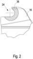
- the jaws 16 have first connecting elements, which are designed as recesses 24 ( Figure 2 ), for connection to second connecting elements of the press loop 12, designed as connecting bolts 26.
- first connecting element and the second connecting element can have other shapes, whereby the shape of the first connecting element and the second connecting element is always designed to ensure a power transmission from the drive unit 10 to the press loop 12.
- first connecting element and the second connecting element have congruent shapes in order to at least partially To create a positive connection.
- the press loop 12 has in the example of Figure 1 three pressing elements 28, which are connected to one another in a chain-like and articulated manner via bolts 30.
- the pressing elements 28 have a common pressing surface 32 on the inside, which comes into contact with the workpieces 33 in order to press the workpieces 33.
- the pressing elements 28 also have pressing loop segments 34, which extend between the bolts 26, 30.
- the pressing loop segments 34 are in particular plate-shaped.
- the jaw 16 of the pressing tongs 18 engages below the uppermost pressing loop segment 34 to connect the recess 24 of the jaw 16 to the respective connecting bolt 26, so that part of the jaw 16 is covered by the uppermost pressing loop segment 34.
- the jaws 16 of the pressing tongs 18 are moved towards each other according to the arrows 22. This movement is transmitted to the pressing loop 12 via the connecting bolts 26, whereby the radius of the pressing loop 12 is reduced and thus the workpieces 33 are pressed.
- the recess 24 is at least partially and in particular completely surrounded by a marking 36.
- This marking has a size which is adapted to the size of the press loop segments 34 of the press loop 12.
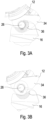
- the press loop segment 34 completely covers the marking 36 when the connecting bolt 26 is correctly seated in the recess 24 of the jaw 16. This gives the user a visual indication that the connecting bolt 26 is correctly positioned in the recess 24 and thus safe handling of the system is ensured.
- Figure 3B shows the situation when the connecting bolt 26 is not correctly in the recess 24. Furthermore, the press loop segment 34 of the press loop 12 partially covers the jaw 16, so that the recess 24 is difficult or impossible for the user to see. Checking that the connecting bolt 26 is correctly seated in the recess 24 is therefore difficult. However, by applying the marking 36, the user can clearly and immediately see that the connecting bolt has not yet been completely and correctly seated in the recess 24. The user is thus given the opportunity to adjust the seat of the connecting bolt 26 and in particular the connection of the press loop 12 to the drive unit 10. Damage to the jaw 16 or injury to the user is thus avoided.
Landscapes
- Engineering & Computer Science (AREA)
- Mechanical Engineering (AREA)
- Press Drives And Press Lines (AREA)
- Clamps And Clips (AREA)
- Load-Engaging Elements For Cranes (AREA)
- Portable Nailing Machines And Staplers (AREA)
- Manufacturing Of Electrical Connectors (AREA)
Claims (9)
- Unité d'entraînement destinée à être utilisée avec une chaîne de pressage pour le pressage de deux pièces à usiner, comportantun entraînement (10) etune pince de pressage (18) reliée à l'entraînement (10), dans laquelle la pince de pressage (18) présente deux mâchoires (16), dans laquelle les mâchoires (16) de la pince de pressage (18) peuvent être déplacées l'une vers l'autre à l'aide de l'entraînement (10) pour la fermeture de la chaîne de pressage (12) et le pressage des deux pièces à usiner (33),dans laquelle les deux mâchoires (16) présentent chacune un premier élément de liaison (24) pour la liaison avec un deuxième élément de liaison (26) de la chaîne de pressage (26),dans laquelle au moins l'un des premiers éléments de liaison (24) est au moins partiellement entouré par un marquage (36).
- Unité d'entraînement selon la revendication 1, caractérisée en ce que la taille du marquage (36) est adaptée à un segment de chaîne de pressage (34) de la chaîne de pressage (12), dans laquelle le marquage (36) n'est entièrement recouvert par le segment de chaîne de pressage (34) que dans la mesure où le deuxième élément de liaison (26) de la chaîne de pressage (12) est entièrement relié au premier élément de liaison (24).
- Unité d'entraînement selon la revendication 1 ou 2,
caractérisée en ce que les deux premiers éléments de liaison (24) sont entourés respectivement d'un marquage (36). - Unité d'entraînement selon l'une des revendications 1 à 3,
caractérisée en ce que le marquage (36) est un marquage à la peinture, un gaufrage de surface, un autocollant ou une surface gravée au laser. - Unité d'entraînement selon l'une des revendications 1 à 4, caractérisée en ce que le marquage (36) est entouré d'un autre repère, de sorte que l'autre repère n'est entièrement recouvert par un segment de chaîne de pressage (34) d'une autre chaîne de pressage que dans la mesure où un troisième élément de liaison de l'autre chaîne de pressage est entièrement relié au premier élément de liaison (24).
- Système comportant une unité d'entraînement selon l'une des revendications 1 à 5 et une chaîne de pressage (12) destinée à être reliée à l'unité d'entraînement (10),dans lequel la chaîne de pressage (12) présente plusieurs éléments de pressage (28) reliés entre eux de manière articulée, à la manière d'une chaîne, à l'aide de boulons (30), dans lequel chaque élément de pressage (28) présente plusieurs segments de chaîne de pressage (34) disposés parallèlement, qui s'étendent d'un boulon (26, 30) au boulon suivant (26, 30) etsur le premier élément de presse (28) et sur le dernier élément de presse (28) est prévu respectivement un deuxième élément de liaison (26) pour la liaison avec le premier élément de liaison (24) de l'unité d'entraînement (10).
- Système selon la revendication 6, caractérisé en ce que les segments de chaîne de pressage (34) sont respectivement en forme de plaque et s'étendent latéralement sur les deuxièmes éléments de liaison (26).
- Système selon la revendication 6 ou 7, caractérisé en ce que l'unité d'entraînement (10) sont reliées l'une à l'autre avec le deuxième élément de liaison (26) respectif en dessous du segment de chaîne de pressage (34) supérieur respectif.
- Système selon l'une des revendications 6 à 8, caractérisé par une pluralité de chaînes de pressage différentes, dans lequel les segments de chaînes de pressage (34) sont réalisés de manière identique pour toutes les chaînes de pressage dans la zone des deuxièmes éléments de liaison (26).
Applications Claiming Priority (2)
| Application Number | Priority Date | Filing Date | Title |
|---|---|---|---|
| DE202020102724.7U DE202020102724U1 (de) | 2020-05-14 | 2020-05-14 | Antriebseinheit |
| PCT/EP2021/061172 WO2021228556A1 (fr) | 2020-05-14 | 2021-04-28 | Unité motrice pour collier de pression |
Publications (2)
| Publication Number | Publication Date |
|---|---|
| EP4149721A1 EP4149721A1 (fr) | 2023-03-22 |
| EP4149721B1 true EP4149721B1 (fr) | 2024-06-12 |
Family
ID=75801562
Family Applications (1)
| Application Number | Title | Priority Date | Filing Date |
|---|---|---|---|
| EP21723665.2A Active EP4149721B1 (fr) | 2020-05-14 | 2021-04-28 | Unité motrice pour collier de pression |
Country Status (7)
| Country | Link |
|---|---|
| US (1) | US12397399B2 (fr) |
| EP (1) | EP4149721B1 (fr) |
| KR (1) | KR20230005867A (fr) |
| CN (1) | CN115605320A (fr) |
| AU (1) | AU2021270710A1 (fr) |
| DE (1) | DE202020102724U1 (fr) |
| WO (1) | WO2021228556A1 (fr) |
Families Citing this family (5)
| Publication number | Priority date | Publication date | Assignee | Title |
|---|---|---|---|---|
| USD906074S1 (en) * | 2018-11-21 | 2020-12-29 | Wezag Gmbh Werkzeugfabrik | Crimping pliers |
| DE202020102724U1 (de) * | 2020-05-14 | 2021-08-17 | Novopress Gmbh Pressen Und Presswerkzeuge & Co. Kommanditgesellschaft | Antriebseinheit |
| DE102021105243B4 (de) | 2021-03-04 | 2022-10-13 | Novopress Gmbh Pressen Und Presswerkzeuge & Co. Kg | Presswerkzeug |
| DE202021102613U1 (de) | 2021-05-12 | 2022-08-18 | Novopress Gmbh Pressen Und Presswerkzeuge & Co. Kommanditgesellschaft | Pressring, Presswerkzeug und Adapterelemente |
| DE102023100782B3 (de) | 2023-01-13 | 2024-05-02 | Novopress Gmbh Pressen Und Presswerkzeuge & Co. Kommanditgesellschaft | Presswerkzeug |
Family Cites Families (27)
| Publication number | Priority date | Publication date | Assignee | Title |
|---|---|---|---|---|
| US4982627A (en) * | 1985-12-18 | 1991-01-08 | Johnson Ken A | Color coded tools |
| US6044686A (en) | 1990-04-12 | 2000-04-04 | Dischler; Helmut | Compression tool for compression molding die |
| EP0904168A1 (fr) * | 1997-03-11 | 1999-03-31 | Gustav Klauke GmbH | Outil de compression |
| US6393950B1 (en) * | 1999-08-03 | 2002-05-28 | Larry G. Crosser | Color coded tools |
| DE10107579B4 (de) | 2000-10-19 | 2012-04-26 | Gustav Klauke Gmbh | Presswerkzeug zum Verpressen von Rohrenden sowie Presseinsatz für eine Pressbacke eines Presswerkzeuges |
| US6923037B2 (en) | 2002-06-17 | 2005-08-02 | Emerson Electric Co. | Assembly for articulating crimp ring and actuator |
| DE50308188D1 (de) * | 2003-11-27 | 2007-10-25 | Geberit Technik Ag | Presswerkzeug |
| US20080216543A1 (en) | 2004-11-24 | 2008-09-11 | Hamm James E | Enhanced Press Apparatus |
| DE202005008125U1 (de) | 2005-05-24 | 2006-10-05 | Herrle, Richard | Presswerkzeug, Pressring und Presszange |
| DE202007013586U1 (de) | 2006-09-30 | 2008-02-21 | Uponor Innovation Ab | Verpresssystem für Rohrverbindungen |
| KR100762293B1 (ko) * | 2007-03-30 | 2007-10-01 | 주식회사 다성테크 | 파이프 압착 체결 장치 |
| US9616553B2 (en) * | 2010-06-04 | 2017-04-11 | Jack L. Marovets | Tool and fastener marking system |
| DE102011011501A1 (de) * | 2011-02-17 | 2012-08-23 | Daimler Ag | Verfahren zum Herstellen einer Nockenwelle |
| DE202011004817U1 (de) * | 2011-04-04 | 2011-06-01 | Novopress GmbH Pressen und Presswerkzeuge & Co. KG, 41460 | Presswerkzeug sowie verpresstes Pressfitting |
| US20130042726A1 (en) * | 2011-08-16 | 2013-02-21 | Da-sen Lin | Method for Marking a Socket |
| US20140209474A1 (en) * | 2013-01-30 | 2014-07-31 | Da-sen Lin | Method for Marking a Tool |
| DE202013007496U1 (de) | 2013-08-21 | 2014-11-28 | Novopress Gmbh Pressen Und Presswerkzeuge & Co. Kg | Pressschlinge zum Verbinden von insbesondere rohrförmigen Werkstücken |
| FR3021386B1 (fr) * | 2014-05-22 | 2017-02-24 | A Raymond Et Cie | Raccord tubulaire a connexion automatique |
| KR101575896B1 (ko) * | 2014-06-09 | 2015-12-08 | 주식회사 서원기술 | 배관용 압착체결구 |
| IT201700041541A1 (it) * | 2017-04-13 | 2018-10-13 | Cembre Spa | Utensile di compressione o taglio e metodo per operare un utensile di compressione o taglio |
| AU2018325983B2 (en) * | 2017-09-04 | 2024-02-01 | Rothenberger Ag | Press die for a pressing tool for pressing round tubular workpiece sections |
| CN207208529U (zh) | 2017-09-08 | 2018-04-10 | 成都宇亨工业制造有限公司 | 一种下药盖 |
| US11578824B2 (en) * | 2018-03-26 | 2023-02-14 | Ridge Tool Company | Crimping tool |
| KR101911507B1 (ko) * | 2018-05-03 | 2018-10-24 | 주식회사 다성테크 | 연결 장치 및 그를 이용한 파이프 압착 연결 장치 |
| EP3639942B2 (fr) * | 2018-10-19 | 2025-07-09 | Emerson Professional Tools AG | Machine à presser pourvu de système de détection destiné à la détection automatisée d'un agencement de mâchoire de compression |
| DE202020102724U1 (de) * | 2020-05-14 | 2021-08-17 | Novopress Gmbh Pressen Und Presswerkzeuge & Co. Kommanditgesellschaft | Antriebseinheit |
| CN115070701B (zh) * | 2021-03-11 | 2025-06-10 | 里奇工具公司 | 可变力压紧工具系统 |
-
2020
- 2020-05-14 DE DE202020102724.7U patent/DE202020102724U1/de active Active
-
2021
- 2021-04-28 KR KR1020227039296A patent/KR20230005867A/ko not_active Withdrawn
- 2021-04-28 EP EP21723665.2A patent/EP4149721B1/fr active Active
- 2021-04-28 CN CN202180034518.5A patent/CN115605320A/zh active Pending
- 2021-04-28 AU AU2021270710A patent/AU2021270710A1/en active Pending
- 2021-04-28 WO PCT/EP2021/061172 patent/WO2021228556A1/fr not_active Ceased
- 2021-04-28 US US17/924,228 patent/US12397399B2/en active Active
Also Published As
| Publication number | Publication date |
|---|---|
| US12397399B2 (en) | 2025-08-26 |
| KR20230005867A (ko) | 2023-01-10 |
| DE202020102724U1 (de) | 2021-08-17 |
| WO2021228556A1 (fr) | 2021-11-18 |
| AU2021270710A1 (en) | 2022-12-15 |
| EP4149721A1 (fr) | 2023-03-22 |
| CN115605320A (zh) | 2023-01-13 |
| US20230127551A1 (en) | 2023-04-27 |
Similar Documents
| Publication | Publication Date | Title |
|---|---|---|
| EP4149721B1 (fr) | Unité motrice pour collier de pression | |
| DE112013003482B4 (de) | Spannvorrichtung | |
| EP3235074B1 (fr) | Pince de compression | |
| WO2012031949A1 (fr) | Clip chirurgical | |
| EP0671985A1 (fr) | Outil de pressage. | |
| EP3180138A1 (fr) | Outil de cintrage et dispositif de préhension servant à manipuler l'outil de cintrage | |
| DE10142131B4 (de) | Vorrichtung zum Anbringen von Dichtungsprofilen an Fahrzeugtüren | |
| DE60015633T2 (de) | Anordnung zum Verbinden eines Betätigungsseiles | |
| EP2691030B1 (fr) | Instrument de pose d'agrafes chirurgicales | |
| EP1117497B1 (fr) | Dispositif d'aboutage, procede d'aboutage par enchevetrement et assemblage realise par aboutage par enchevetrement | |
| DE102009060097A1 (de) | Abdeckungsvorrichtung | |
| DE202018106191U1 (de) | Reifengreifer zum Greifen eines Reifens an seinem Außenumfang | |
| DE202021102613U1 (de) | Pressring, Presswerkzeug und Adapterelemente | |
| DE102016101466B4 (de) | Fahrradbremse | |
| WO2022184381A1 (fr) | Outil de pressage | |
| DE102012025353B4 (de) | Vorrichtung zum Runddrücken eines hohlzylindrischen Werkstücks | |
| EP0497780B1 (fr) | Procede de cintrage oppose d'une tole | |
| DE202019105099U1 (de) | Abdeckvorrichtung für eine Maschinenkabine | |
| DE3840556A1 (de) | Nockenstruktur | |
| EP2848544B1 (fr) | Unité de cylindre de préhension pour une étiqueteuse | |
| DE2012697C3 (de) | Antriebsgelenkkettenanordnung | |
| EP0266624A2 (fr) | Support d'outil supérieur pour un poinçon ou un élément similaire | |
| DE102006033279A1 (de) | Verfahren und Vorrichtung zum Verbinden mehrerer Kabel mit einem Bauteil sowie Nietbuchse hierfür | |
| DE102015114870B4 (de) | Werkzeug zur fahrzeugtürseitigen Montage eines einen Fahrzeugtürzustand kontrollierenden Bindeglieds und Verfahren zur Montage | |
| DE102023100782B3 (de) | Presswerkzeug |
Legal Events
| Date | Code | Title | Description |
|---|---|---|---|
| STAA | Information on the status of an ep patent application or granted ep patent |
Free format text: STATUS: UNKNOWN |
|
| STAA | Information on the status of an ep patent application or granted ep patent |
Free format text: STATUS: THE INTERNATIONAL PUBLICATION HAS BEEN MADE |
|
| PUAI | Public reference made under article 153(3) epc to a published international application that has entered the european phase |
Free format text: ORIGINAL CODE: 0009012 |
|
| STAA | Information on the status of an ep patent application or granted ep patent |
Free format text: STATUS: REQUEST FOR EXAMINATION WAS MADE |
|
| 17P | Request for examination filed |
Effective date: 20221114 |
|
| AK | Designated contracting states |
Kind code of ref document: A1 Designated state(s): AL AT BE BG CH CY CZ DE DK EE ES FI FR GB GR HR HU IE IS IT LI LT LU LV MC MK MT NL NO PL PT RO RS SE SI SK SM TR |
|
| DAV | Request for validation of the european patent (deleted) | ||
| DAX | Request for extension of the european patent (deleted) | ||
| GRAP | Despatch of communication of intention to grant a patent |
Free format text: ORIGINAL CODE: EPIDOSNIGR1 |
|
| STAA | Information on the status of an ep patent application or granted ep patent |
Free format text: STATUS: GRANT OF PATENT IS INTENDED |
|
| INTG | Intention to grant announced |
Effective date: 20240103 |
|
| GRAS | Grant fee paid |
Free format text: ORIGINAL CODE: EPIDOSNIGR3 |
|
| GRAA | (expected) grant |
Free format text: ORIGINAL CODE: 0009210 |
|
| STAA | Information on the status of an ep patent application or granted ep patent |
Free format text: STATUS: THE PATENT HAS BEEN GRANTED |
|
| AK | Designated contracting states |
Kind code of ref document: B1 Designated state(s): AL AT BE BG CH CY CZ DE DK EE ES FI FR GB GR HR HU IE IS IT LI LT LU LV MC MK MT NL NO PL PT RO RS SE SI SK SM TR |
|
| REG | Reference to a national code |
Ref country code: GB Ref legal event code: FG4D Free format text: NOT ENGLISH |
|
| REG | Reference to a national code |
Ref country code: CH Ref legal event code: EP |
|
| REG | Reference to a national code |
Ref country code: DE Ref legal event code: R096 Ref document number: 502021003996 Country of ref document: DE |
|
| REG | Reference to a national code |
Ref country code: IE Ref legal event code: FG4D Free format text: LANGUAGE OF EP DOCUMENT: GERMAN |
|
| P01 | Opt-out of the competence of the unified patent court (upc) registered |
Free format text: CASE NUMBER: APP_34990/2024 Effective date: 20240611 |
|
| PG25 | Lapsed in a contracting state [announced via postgrant information from national office to epo] |
Ref country code: BG Free format text: LAPSE BECAUSE OF FAILURE TO SUBMIT A TRANSLATION OF THE DESCRIPTION OR TO PAY THE FEE WITHIN THE PRESCRIBED TIME-LIMIT Effective date: 20240612 |
|
| PG25 | Lapsed in a contracting state [announced via postgrant information from national office to epo] |
Ref country code: FI Free format text: LAPSE BECAUSE OF FAILURE TO SUBMIT A TRANSLATION OF THE DESCRIPTION OR TO PAY THE FEE WITHIN THE PRESCRIBED TIME-LIMIT Effective date: 20240612 Ref country code: HR Free format text: LAPSE BECAUSE OF FAILURE TO SUBMIT A TRANSLATION OF THE DESCRIPTION OR TO PAY THE FEE WITHIN THE PRESCRIBED TIME-LIMIT Effective date: 20240612 |
|
| REG | Reference to a national code |
Ref country code: LT Ref legal event code: MG9D |
|
| PG25 | Lapsed in a contracting state [announced via postgrant information from national office to epo] |
Ref country code: GR Free format text: LAPSE BECAUSE OF FAILURE TO SUBMIT A TRANSLATION OF THE DESCRIPTION OR TO PAY THE FEE WITHIN THE PRESCRIBED TIME-LIMIT Effective date: 20240913 |
|
| REG | Reference to a national code |
Ref country code: NL Ref legal event code: MP Effective date: 20240612 |
|
| PG25 | Lapsed in a contracting state [announced via postgrant information from national office to epo] |
Ref country code: ES Free format text: LAPSE BECAUSE OF FAILURE TO SUBMIT A TRANSLATION OF THE DESCRIPTION OR TO PAY THE FEE WITHIN THE PRESCRIBED TIME-LIMIT Effective date: 20240612 |
|
| PG25 | Lapsed in a contracting state [announced via postgrant information from national office to epo] |
Ref country code: LV Free format text: LAPSE BECAUSE OF FAILURE TO SUBMIT A TRANSLATION OF THE DESCRIPTION OR TO PAY THE FEE WITHIN THE PRESCRIBED TIME-LIMIT Effective date: 20240612 |
|
| PG25 | Lapsed in a contracting state [announced via postgrant information from national office to epo] |
Ref country code: NO Free format text: LAPSE BECAUSE OF FAILURE TO SUBMIT A TRANSLATION OF THE DESCRIPTION OR TO PAY THE FEE WITHIN THE PRESCRIBED TIME-LIMIT Effective date: 20240912 Ref country code: LV Free format text: LAPSE BECAUSE OF FAILURE TO SUBMIT A TRANSLATION OF THE DESCRIPTION OR TO PAY THE FEE WITHIN THE PRESCRIBED TIME-LIMIT Effective date: 20240612 Ref country code: HR Free format text: LAPSE BECAUSE OF FAILURE TO SUBMIT A TRANSLATION OF THE DESCRIPTION OR TO PAY THE FEE WITHIN THE PRESCRIBED TIME-LIMIT Effective date: 20240612 Ref country code: GR Free format text: LAPSE BECAUSE OF FAILURE TO SUBMIT A TRANSLATION OF THE DESCRIPTION OR TO PAY THE FEE WITHIN THE PRESCRIBED TIME-LIMIT Effective date: 20240913 Ref country code: FI Free format text: LAPSE BECAUSE OF FAILURE TO SUBMIT A TRANSLATION OF THE DESCRIPTION OR TO PAY THE FEE WITHIN THE PRESCRIBED TIME-LIMIT Effective date: 20240612 Ref country code: ES Free format text: LAPSE BECAUSE OF FAILURE TO SUBMIT A TRANSLATION OF THE DESCRIPTION OR TO PAY THE FEE WITHIN THE PRESCRIBED TIME-LIMIT Effective date: 20240612 Ref country code: BG Free format text: LAPSE BECAUSE OF FAILURE TO SUBMIT A TRANSLATION OF THE DESCRIPTION OR TO PAY THE FEE WITHIN THE PRESCRIBED TIME-LIMIT Effective date: 20240612 Ref country code: RS Free format text: LAPSE BECAUSE OF FAILURE TO SUBMIT A TRANSLATION OF THE DESCRIPTION OR TO PAY THE FEE WITHIN THE PRESCRIBED TIME-LIMIT Effective date: 20240912 |
|
| PG25 | Lapsed in a contracting state [announced via postgrant information from national office to epo] |
Ref country code: NL Free format text: LAPSE BECAUSE OF FAILURE TO SUBMIT A TRANSLATION OF THE DESCRIPTION OR TO PAY THE FEE WITHIN THE PRESCRIBED TIME-LIMIT Effective date: 20240612 |
|
| PG25 | Lapsed in a contracting state [announced via postgrant information from national office to epo] |
Ref country code: NL Free format text: LAPSE BECAUSE OF FAILURE TO SUBMIT A TRANSLATION OF THE DESCRIPTION OR TO PAY THE FEE WITHIN THE PRESCRIBED TIME-LIMIT Effective date: 20240612 |
|
| PG25 | Lapsed in a contracting state [announced via postgrant information from national office to epo] |
Ref country code: PT Free format text: LAPSE BECAUSE OF FAILURE TO SUBMIT A TRANSLATION OF THE DESCRIPTION OR TO PAY THE FEE WITHIN THE PRESCRIBED TIME-LIMIT Effective date: 20241014 |
|
| PG25 | Lapsed in a contracting state [announced via postgrant information from national office to epo] |
Ref country code: PT Free format text: LAPSE BECAUSE OF FAILURE TO SUBMIT A TRANSLATION OF THE DESCRIPTION OR TO PAY THE FEE WITHIN THE PRESCRIBED TIME-LIMIT Effective date: 20241014 |
|
| PG25 | Lapsed in a contracting state [announced via postgrant information from national office to epo] |
Ref country code: PL Free format text: LAPSE BECAUSE OF FAILURE TO SUBMIT A TRANSLATION OF THE DESCRIPTION OR TO PAY THE FEE WITHIN THE PRESCRIBED TIME-LIMIT Effective date: 20240612 |
|
| PG25 | Lapsed in a contracting state [announced via postgrant information from national office to epo] |
Ref country code: EE Free format text: LAPSE BECAUSE OF FAILURE TO SUBMIT A TRANSLATION OF THE DESCRIPTION OR TO PAY THE FEE WITHIN THE PRESCRIBED TIME-LIMIT Effective date: 20240612 |
|
| PG25 | Lapsed in a contracting state [announced via postgrant information from national office to epo] |
Ref country code: IS Free format text: LAPSE BECAUSE OF FAILURE TO SUBMIT A TRANSLATION OF THE DESCRIPTION OR TO PAY THE FEE WITHIN THE PRESCRIBED TIME-LIMIT Effective date: 20241012 |
|
| PG25 | Lapsed in a contracting state [announced via postgrant information from national office to epo] |
Ref country code: SK Free format text: LAPSE BECAUSE OF FAILURE TO SUBMIT A TRANSLATION OF THE DESCRIPTION OR TO PAY THE FEE WITHIN THE PRESCRIBED TIME-LIMIT Effective date: 20240612 Ref country code: RO Free format text: LAPSE BECAUSE OF FAILURE TO SUBMIT A TRANSLATION OF THE DESCRIPTION OR TO PAY THE FEE WITHIN THE PRESCRIBED TIME-LIMIT Effective date: 20240612 |
|
| PG25 | Lapsed in a contracting state [announced via postgrant information from national office to epo] |
Ref country code: SM Free format text: LAPSE BECAUSE OF FAILURE TO SUBMIT A TRANSLATION OF THE DESCRIPTION OR TO PAY THE FEE WITHIN THE PRESCRIBED TIME-LIMIT Effective date: 20240612 |
|
| PG25 | Lapsed in a contracting state [announced via postgrant information from national office to epo] |
Ref country code: SM Free format text: LAPSE BECAUSE OF FAILURE TO SUBMIT A TRANSLATION OF THE DESCRIPTION OR TO PAY THE FEE WITHIN THE PRESCRIBED TIME-LIMIT Effective date: 20240612 Ref country code: SK Free format text: LAPSE BECAUSE OF FAILURE TO SUBMIT A TRANSLATION OF THE DESCRIPTION OR TO PAY THE FEE WITHIN THE PRESCRIBED TIME-LIMIT Effective date: 20240612 Ref country code: RO Free format text: LAPSE BECAUSE OF FAILURE TO SUBMIT A TRANSLATION OF THE DESCRIPTION OR TO PAY THE FEE WITHIN THE PRESCRIBED TIME-LIMIT Effective date: 20240612 Ref country code: PL Free format text: LAPSE BECAUSE OF FAILURE TO SUBMIT A TRANSLATION OF THE DESCRIPTION OR TO PAY THE FEE WITHIN THE PRESCRIBED TIME-LIMIT Effective date: 20240612 Ref country code: IS Free format text: LAPSE BECAUSE OF FAILURE TO SUBMIT A TRANSLATION OF THE DESCRIPTION OR TO PAY THE FEE WITHIN THE PRESCRIBED TIME-LIMIT Effective date: 20241012 Ref country code: EE Free format text: LAPSE BECAUSE OF FAILURE TO SUBMIT A TRANSLATION OF THE DESCRIPTION OR TO PAY THE FEE WITHIN THE PRESCRIBED TIME-LIMIT Effective date: 20240612 |
|
| PG25 | Lapsed in a contracting state [announced via postgrant information from national office to epo] |
Ref country code: IT Free format text: LAPSE BECAUSE OF FAILURE TO SUBMIT A TRANSLATION OF THE DESCRIPTION OR TO PAY THE FEE WITHIN THE PRESCRIBED TIME-LIMIT Effective date: 20240612 |
|
| REG | Reference to a national code |
Ref country code: DE Ref legal event code: R097 Ref document number: 502021003996 Country of ref document: DE |
|
| PG25 | Lapsed in a contracting state [announced via postgrant information from national office to epo] |
Ref country code: DK Free format text: LAPSE BECAUSE OF FAILURE TO SUBMIT A TRANSLATION OF THE DESCRIPTION OR TO PAY THE FEE WITHIN THE PRESCRIBED TIME-LIMIT Effective date: 20240612 |
|
| PLBE | No opposition filed within time limit |
Free format text: ORIGINAL CODE: 0009261 |
|
| STAA | Information on the status of an ep patent application or granted ep patent |
Free format text: STATUS: NO OPPOSITION FILED WITHIN TIME LIMIT |
|
| 26N | No opposition filed |
Effective date: 20250313 |
|
| PGFP | Annual fee paid to national office [announced via postgrant information from national office to epo] |
Ref country code: DE Payment date: 20250415 Year of fee payment: 5 |
|
| PGFP | Annual fee paid to national office [announced via postgrant information from national office to epo] |
Ref country code: CH Payment date: 20250501 Year of fee payment: 5 |
|
| PGFP | Annual fee paid to national office [announced via postgrant information from national office to epo] |
Ref country code: AT Payment date: 20250721 Year of fee payment: 5 |
|
| PGFP | Annual fee paid to national office [announced via postgrant information from national office to epo] |
Ref country code: CZ Payment date: 20250415 Year of fee payment: 5 |
|
| PG25 | Lapsed in a contracting state [announced via postgrant information from national office to epo] |
Ref country code: SE Free format text: LAPSE BECAUSE OF FAILURE TO SUBMIT A TRANSLATION OF THE DESCRIPTION OR TO PAY THE FEE WITHIN THE PRESCRIBED TIME-LIMIT Effective date: 20240612 |
|
| PG25 | Lapsed in a contracting state [announced via postgrant information from national office to epo] |
Ref country code: LU Free format text: LAPSE BECAUSE OF NON-PAYMENT OF DUE FEES Effective date: 20250428 |
|
| PG25 | Lapsed in a contracting state [announced via postgrant information from national office to epo] |
Ref country code: MC Free format text: LAPSE BECAUSE OF FAILURE TO SUBMIT A TRANSLATION OF THE DESCRIPTION OR TO PAY THE FEE WITHIN THE PRESCRIBED TIME-LIMIT Effective date: 20240612 |
|
| GBPC | Gb: european patent ceased through non-payment of renewal fee |
Effective date: 20250428 |
|
| REG | Reference to a national code |
Ref country code: BE Ref legal event code: MM Effective date: 20250430 |
|
| PG25 | Lapsed in a contracting state [announced via postgrant information from national office to epo] |
Ref country code: GB Free format text: LAPSE BECAUSE OF NON-PAYMENT OF DUE FEES Effective date: 20250428 |
|
| PG25 | Lapsed in a contracting state [announced via postgrant information from national office to epo] |
Ref country code: FR Free format text: LAPSE BECAUSE OF NON-PAYMENT OF DUE FEES Effective date: 20250430 |
|
| PG25 | Lapsed in a contracting state [announced via postgrant information from national office to epo] |
Ref country code: BE Free format text: LAPSE BECAUSE OF NON-PAYMENT OF DUE FEES Effective date: 20250430 |
|
| PG25 | Lapsed in a contracting state [announced via postgrant information from national office to epo] |
Ref country code: IE Free format text: LAPSE BECAUSE OF NON-PAYMENT OF DUE FEES Effective date: 20250428 |