EP0266624A2 - Support d'outil supérieur pour un poinçon ou un élément similaire - Google Patents
Support d'outil supérieur pour un poinçon ou un élément similaire Download PDFInfo
- Publication number
- EP0266624A2 EP0266624A2 EP87115367A EP87115367A EP0266624A2 EP 0266624 A2 EP0266624 A2 EP 0266624A2 EP 87115367 A EP87115367 A EP 87115367A EP 87115367 A EP87115367 A EP 87115367A EP 0266624 A2 EP0266624 A2 EP 0266624A2
- Authority
- EP
- European Patent Office
- Prior art keywords
- tool
- punching
- punch
- closure cap
- carrier body
- Prior art date
- Legal status (The legal status is an assumption and is not a legal conclusion. Google has not performed a legal analysis and makes no representation as to the accuracy of the status listed.)
- Granted
Links
- 238000004080 punching Methods 0.000 claims abstract description 66
- 230000005540 biological transmission Effects 0.000 claims description 12
- 238000003780 insertion Methods 0.000 description 3
- 230000037431 insertion Effects 0.000 description 3
- 238000010276 construction Methods 0.000 description 2
- 230000006978 adaptation Effects 0.000 description 1
- 239000000969 carrier Substances 0.000 description 1
- 210000003127 knee Anatomy 0.000 description 1
- 238000000034 method Methods 0.000 description 1
Images


Classifications
-
- B—PERFORMING OPERATIONS; TRANSPORTING
- B21—MECHANICAL METAL-WORKING WITHOUT ESSENTIALLY REMOVING MATERIAL; PUNCHING METAL
- B21D—WORKING OR PROCESSING OF SHEET METAL OR METAL TUBES, RODS OR PROFILES WITHOUT ESSENTIALLY REMOVING MATERIAL; PUNCHING METAL
- B21D28/00—Shaping by press-cutting; Perforating
- B21D28/24—Perforating, i.e. punching holes
- B21D28/34—Perforating tools; Die holders
-
- B—PERFORMING OPERATIONS; TRANSPORTING
- B21—MECHANICAL METAL-WORKING WITHOUT ESSENTIALLY REMOVING MATERIAL; PUNCHING METAL
- B21D—WORKING OR PROCESSING OF SHEET METAL OR METAL TUBES, RODS OR PROFILES WITHOUT ESSENTIALLY REMOVING MATERIAL; PUNCHING METAL
- B21D37/00—Tools as parts of machines covered by this subclass
- B21D37/04—Movable or exchangeable mountings for tools
Definitions
- the invention relates to an upper tool carrier for a punch or the like. According to the preamble of claim 1.
- the following explanations apply not only to upper tool carriers of machine tools designed as punching dies, but also, for example, when two or more clinker tools are arranged next to one another in the upper tool carrier.
- the teaching of the invention is therefore not only limited to a punch and punching tools, but can also be applied to all machine tools in which comparable problems occur.
- the teaching of the invention is explained here and below using the preferred exemplary embodiment of an upper tool carrier for a punch in order to facilitate understanding of the teaching.
- the ends of the punching tools are provided with hammer-head-like extensions and the mounting plate and the closure cap are provided with support flanges corresponding to the hammer-head-like extensions, so that the punching tools cannot slide down out of the tool guides.
- the closure cap is pivotably articulated on the carrier body or on the receiving plate via a pivot axis and can be locked with the carrier body or the receiving plate by means of a locking device which is arranged on the opposite transverse side.
- the locking device consists of one on the Take plate in the horizontal plane pivotally hinged bolt and a provided on the closure cap, one-sided open bolt receptacle, wherein the locking bolt can be pivoted into the bolt receptacle and clamped by means of a clamping nut.
- receiving spaces for the upper ends of the punching tools are provided on the carrier body above the tool guides and below a force transmission surface, and these receiving spaces can be bridged by means of force transmission slides which can be displaced essentially perpendicular to the punching direction.
- Each punching tool is assigned a lifting lever arranged on the carrier body, one end of which laterally grips the upper end of the associated punching tool from below, so that the upper end of the punching tool can be raised into the cavity by means of the lifting lever when the power transmission slide is retracted.
- pneumatic drives or the like which are not to be explained in detail are provided.
- the above-described upper tool carrier which forms the starting point for the teaching of the invention, can practically no longer be improved with regard to the quick interchangeability of the punching tools.
- the half-shell design of the mounting plate and the closure cap for forming the tool guides is problematic in practice. If the locking device is too tight, it can happen that the punching tools are clamped in the tool guides. The upper tool carrier is then inoperable. The result is sometimes damaged punching tools and possibly also damaged other machine parts.
- the invention is based on the object of designing and developing the known upper tool carrier for a punch or the like so that the guidance of the stamping tools is unaffected by the attachment of the closure cap to the carrier body.
- the upper tool carrier according to the invention in which the above-mentioned object is achieved, is described by the features of the characterizing part of claim 1.
- the factory is assumed Tool guides each half-shell like part in the cap, to be provided in part in the mounting plate. Rather, according to the invention, the tool guides are provided completely and closed in the mounting plate, the mounting plate now being part of the closure cap and thus being completely removable from the carrier body.
- the punching tools can be inserted or removed from the tool guides practically as quickly in the punching direction or in the direction perpendicular to the receiving plate as was previously possible with the insertion or removal from the half-shell receptacles .
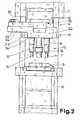
- FIG. 1 shows, as a special, preferred exemplary embodiment of the invention, a machine tool in the form of a hole punch with a C-shaped machine body 1, only indicated, a lower tool carrier 2 formed or arranged on the machine body 1 with a lower tool 3 and one on the machine body 1 arranged or executed top tool carrier 4 with an upper tool, here a punching tool 5.
- a drive head 6, for example in the form of a hydraulic cylinder piston Arrangement sits, with the help of which the punch 5 can be lowered to the lower tool 3 during operation.
- the upper tool carrier 4 shown here is characterized in that at least two, to be precise three punching tools 5 arranged here side by side are provided.
- each punch 5 consists of a punch 7, a punch holder 8 and a union nut 9 connecting the punch 7 to the punch holder 8.
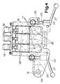
- the three punching tools 5, as shown in FIG. 2, are arranged as close as possible to one another.
- Fig. 1 shows that the upper tool carrier 5 in the embodiment shown here initially has a carrier body 10 and a receiving plate 11.
- Fig. 3 makes it clear that in the mounting plate 11 side by side, extending in the punching direction tool guides 12 are provided for each punch 5.
- 1, 2 and 3 make further clear in connection with this that the upper tool carrier 4 has a closure cap 14 fastened to the carrier body 10, in particular and in the exemplary embodiment shown here pivotable about a pivot axis 13 on the carrier body 10.
- 1 and 2 finally show in connection that the upper ends of the punch 5 in the tool guides 12, limited in one direction by support flanges 15, are guided in the punching direction, here vertically.
- the support flanges 15 3 shows well. They serve to prevent the punching tools 5 from falling out of the tool guides 12 downwards.
- receiving spaces 17 for the upper ends of the punching tools 5 are provided on the carrier body 10 above the tool guides 12 and below a force transmission surface 16.
- the receiving spaces 17 can be bridged with the aid of force transmission slides 18 or the like, which can be displaced essentially perpendicular to the punching direction, with the aid of actuators 19 designed here as pneumatic cylinder-piston units.
- the force transmission surface 16 is arranged on the underside of the drive head 6 . This technique ensures that only that punch 5 is actively moved downward during the downward stroke of the force transmission surface 16, the force transmission slide 18 of which bridges the associated receiving space 17, while the other two punching tools 5 can move back into the respectively assigned receiving space 17.
- closure cap 14 includes the mounting plate 11, that the tool guides 12 are closed in a ring in the plane perpendicular to the punching direction and that the punching tools 5 at Carrier body 10 of removed, in particular pivoted, closure cap 14 can be inserted or withdrawn from tool guides 12 in the punching direction or in the direction perpendicular to receiving plate 11.
- Fig. 3 further shows that in adaptation to the previously described lifting lever 20 for lifting the ends of the punching tools 5, the closure cap 14 on the side facing the carrier body 10 on each tool guide 12 has an engaging channel 21 for the tool guide 12 opening under the support flange 15 has the lifting lever 20.
- the lifting levers 20 can engage through the engagement channels 21 to below the edge of the punching tool 5, in particular the hammer-head-like extension at the upper end. This insertion of the lifting lever 20 takes place with the pivotable articulation of the closure cap 14 by itself when the closure cap 14 is pivoted toward the carrier body 10.
- the center point in the preferred embodiment shown and shown here the articulation axis 13 for the articulation of the closure cap 14 on the carrier body 10 is arranged laterally at a considerable distance, preferably at a distance of approximately 100 mm to 200 mm, in particular approximately 150 mm, from the nearest edge of the nearest tool guide 12.
- This laterally cantilever-like construction of the carrier body 10 and the closure cap 14 has the advantage that the upper ends of the punching tools 5 can easily be pulled up out of the tool guides 12 in the mounting plate 11.
- the lateral minimum distance of the articulation axis 13 from the closest tool guide 12 ensures that the tool guides 12 can be moved far enough away from the carrier body 10 even in the presence of projecting parts of the upper tool carrier 4 in order to completely clear the insertion path for the punching tools 5.
- the closure cap 14 can be locked on the carrier body 10 by means of a locking device 22, in particular a locking device 22 arranged on the side opposite the articulation axis 13. 2 and 4 clearly show in the context that according to the preferred teaching of the invention, a second locking device 23 is provided near the articulation axis 13 and, according to the preferred teaching of the invention, below a part 24 located here and extending to the articulation axis 13 the cap 14 is arranged.
- the locking device 23, like the locking device 22, can be configured in the manner explained in the introduction, namely consist of a locking bolt 25 articulated on the carrier body 10 in the horizontal plane and a locking receptacle 26 provided on the locking cap 14, preferably open on one side and on the transverse side , wherein the locking bolt 25 can be pivoted into the locking receptacle 26 and locked by means of a clamping nut 27 or the like.
- the clamping nut 27 or the like can be designed as a knee clamping lever, as can be seen particularly clearly in FIG. 4.
- the arrangement of the second locking device 23 below the part 24 of the closure cap 14 creates the possibility, after pivoting the locking bolt 25 with the clamping nut 27 to the left in FIG. 2, to also pivot the closure cap 14 to the left without colliding with the locking device 23.
Landscapes
- Engineering & Computer Science (AREA)
- Mechanical Engineering (AREA)
- Punching Or Piercing (AREA)
- Mounting, Exchange, And Manufacturing Of Dies (AREA)
- Perforating, Stamping-Out Or Severing By Means Other Than Cutting (AREA)
- Bending Of Plates, Rods, And Pipes (AREA)
- Passenger Equipment (AREA)
- Jigs For Machine Tools (AREA)
Priority Applications (1)
| Application Number | Priority Date | Filing Date | Title |
|---|---|---|---|
| AT87115367T ATE102096T1 (de) | 1986-11-04 | 1987-10-21 | Oberer werkzeugtraeger fuer eine stanze od. dgl. |
Applications Claiming Priority (2)
| Application Number | Priority Date | Filing Date | Title |
|---|---|---|---|
| DE3637488 | 1986-11-04 | ||
| DE3637488A DE3637488C1 (de) | 1986-11-04 | 1986-11-04 | Oberer Werkzeugtraeger fuer eine Stanze od.dgl. |
Publications (3)
| Publication Number | Publication Date |
|---|---|
| EP0266624A2 true EP0266624A2 (fr) | 1988-05-11 |
| EP0266624A3 EP0266624A3 (en) | 1990-01-17 |
| EP0266624B1 EP0266624B1 (fr) | 1994-03-02 |
Family
ID=6313105
Family Applications (1)
| Application Number | Title | Priority Date | Filing Date |
|---|---|---|---|
| EP87115367A Expired - Lifetime EP0266624B1 (fr) | 1986-11-04 | 1987-10-21 | Support d'outil supérieur pour un poinçon ou un élément similaire |
Country Status (8)
| Country | Link |
|---|---|
| EP (1) | EP0266624B1 (fr) |
| JP (1) | JPS63123540A (fr) |
| AT (1) | ATE102096T1 (fr) |
| BR (1) | BR8705862A (fr) |
| CA (1) | CA1292422C (fr) |
| DE (2) | DE3637488C1 (fr) |
| ES (1) | ES2050104T3 (fr) |
| MX (1) | MX161211A (fr) |
Families Citing this family (6)
| Publication number | Priority date | Publication date | Assignee | Title |
|---|---|---|---|---|
| CN102310141A (zh) * | 2011-09-01 | 2012-01-11 | 天津大田包装容器有限公司 | 一种用于钢桶桶口铆压锁装的双工位铆压模具 |
| CN103286224B (zh) * | 2012-10-09 | 2017-06-06 | 湖南同心实业有限责任公司 | 多用快装型模架 |
| CN108326152B (zh) * | 2018-01-25 | 2020-01-07 | 湖州龙溢机械有限公司 | 一种可调节汽车油封座冲压装置 |
| CN108372221B (zh) * | 2018-05-29 | 2020-01-07 | 合肥智权信息科技有限公司 | 一种效率高的冲压生产线 |
| CN109396316B (zh) * | 2018-12-24 | 2024-01-09 | 重庆江东机械有限责任公司 | 一种锻压机两工位压头更换装置 |
| CN112658136A (zh) * | 2020-12-11 | 2021-04-16 | 安徽贵达汽车部件有限公司 | 一种刹车片钢背压钉模具 |
Family Cites Families (7)
| Publication number | Priority date | Publication date | Assignee | Title |
|---|---|---|---|---|
| NL299765A (fr) * | 1900-01-01 | |||
| GB1038743A (en) * | 1964-04-24 | 1966-08-10 | Smeets Gerard G F | Multiple head punch holder |
| FR1445424A (fr) * | 1964-09-03 | 1966-07-08 | Gilbos Const Pvba | Dispositif pour sélectionner les poinçons sur une presse à poinçonner |
| DE1552618A1 (de) * | 1966-04-14 | 1970-04-09 | Peter Heck | Vorrichtung zum Lochen von flaechenhaften Werkstuecken |
| FR2389425B1 (fr) * | 1977-05-03 | 1981-02-27 | Bo Ermanno | |
| DE2940661A1 (de) * | 1979-10-06 | 1981-04-09 | Fa. Muhr und Bender, 5952 Attendorn | Werkzeugmaschine |
| DE3440093A1 (de) * | 1984-11-02 | 1986-05-07 | Fa. Muhr und Bender, 5952 Attendorn | Werkzeugmaschine, insbesondere stanze |
-
1986
- 1986-11-04 DE DE3637488A patent/DE3637488C1/de not_active Expired
-
1987
- 1987-10-14 JP JP62257484A patent/JPS63123540A/ja active Granted
- 1987-10-21 ES ES87115367T patent/ES2050104T3/es not_active Expired - Lifetime
- 1987-10-21 DE DE87115367T patent/DE3789198D1/de not_active Expired - Fee Related
- 1987-10-21 EP EP87115367A patent/EP0266624B1/fr not_active Expired - Lifetime
- 1987-10-21 AT AT87115367T patent/ATE102096T1/de active
- 1987-11-03 BR BR8705862A patent/BR8705862A/pt unknown
- 1987-11-03 CA CA000550945A patent/CA1292422C/fr not_active Expired - Fee Related
- 1987-11-04 MX MX9135A patent/MX161211A/es unknown
Also Published As
| Publication number | Publication date |
|---|---|
| BR8705862A (pt) | 1988-06-14 |
| ATE102096T1 (de) | 1994-03-15 |
| MX161211A (es) | 1990-08-20 |
| JPH0472622B2 (fr) | 1992-11-18 |
| CA1292422C (fr) | 1991-11-26 |
| DE3789198D1 (de) | 1994-04-07 |
| EP0266624A3 (en) | 1990-01-17 |
| DE3637488C1 (de) | 1988-02-25 |
| EP0266624B1 (fr) | 1994-03-02 |
| JPS63123540A (ja) | 1988-05-27 |
| ES2050104T3 (es) | 1994-05-16 |
Similar Documents
| Publication | Publication Date | Title |
|---|---|---|
| EP0468335B1 (fr) | Outil pour le sertissage d'un connecteur à un conducteur et une isolation | |
| EP0595074B1 (fr) | Dispositif de serrage | |
| EP0116684B1 (fr) | Presse avec des guides de transfert échangeables simultanément avec les outils | |
| EP0616859B1 (fr) | Equipement de transfert pour la manutention de pièces | |
| DE29716104U1 (de) | Spannvorrichtung, insbesondere Maschinenschraubstock | |
| DE9314483U1 (de) | Vorrichtung zur lagefixierten Positionierung einer Palette auf einem Aufspanntisch | |
| EP0266624B1 (fr) | Support d'outil supérieur pour un poinçon ou un élément similaire | |
| EP0266625B1 (fr) | Support d'outil supérieur pour un poinçon ou un élément similaire | |
| EP0143257B1 (fr) | Raccordement d'outil d'une presse de découpage, notamment d'une presse de découpage à plateau revolver, pour le changement d'outil | |
| DE29903940U1 (de) | Verriegelungseinrichtung für Container auf dem Chassis eines Fahrzeuges | |
| DE3135266C2 (de) | Schneidpresse zum Herausschneiden oder -trennen von Teilen aus einer Werkstücktafel | |
| EP0180146B1 (fr) | Poinçonneuse | |
| DE19751238A1 (de) | Vorrichtung zum Herstellen eines Werkstückes durch Stanzen | |
| DE3838198A1 (de) | Werkzeugmaschine | |
| EP0925126A1 (fr) | Machine a usiner des plats dotee d'une serre-flan reparti en segments | |
| EP0076783B1 (fr) | Machine à cintrer des tubes et des barres profilés | |
| EP0250646A2 (fr) | Dispositif de levage et d'abaissement d'un support de pied et d'un support de tête d'un sommier | |
| DE3703700C2 (de) | Stanzpresse mit einer automatischen Werkzeugwechselvorrichtung | |
| DE3805846C1 (en) | Tool arrangement for making oblique cuts in metal sheets by fine blanking or punching | |
| EP0481326B1 (fr) | Dispositif de serrage | |
| EP0128342B1 (fr) | Presse avec un dispositif pour l'éjection des pièces et un dispositif pour l'ajustage de l'altitude de fermeture | |
| DE3326055A1 (de) | Ueberfuehrungseinrichtung fuer schmiedemaschinen | |
| EP0361210A2 (fr) | Presse à barres de transfert | |
| DE3876152T2 (de) | Blechtiefziehvorrichtung. | |
| DE102023001583A1 (de) | Haltevorrichtung |
Legal Events
| Date | Code | Title | Description |
|---|---|---|---|
| PUAI | Public reference made under article 153(3) epc to a published international application that has entered the european phase |
Free format text: ORIGINAL CODE: 0009012 |
|
| AK | Designated contracting states |
Kind code of ref document: A2 Designated state(s): AT BE CH DE ES FR GB GR IT LI LU NL SE |
|
| 17P | Request for examination filed |
Effective date: 19890104 |
|
| PUAL | Search report despatched |
Free format text: ORIGINAL CODE: 0009013 |
|
| AK | Designated contracting states |
Kind code of ref document: A3 Designated state(s): AT BE CH DE ES FR GB GR IT LI LU NL SE |
|
| 17Q | First examination report despatched |
Effective date: 19910425 |
|
| GRAA | (expected) grant |
Free format text: ORIGINAL CODE: 0009210 |
|
| AK | Designated contracting states |
Kind code of ref document: B1 Designated state(s): AT BE CH DE ES FR GB GR IT LI LU NL SE |
|
| PG25 | Lapsed in a contracting state [announced via postgrant information from national office to epo] |
Ref country code: GR Free format text: LAPSE BECAUSE OF FAILURE TO SUBMIT A TRANSLATION OF THE DESCRIPTION OR TO PAY THE FEE WITHIN THE PRESCRIBED TIME-LIMIT Effective date: 19940302 |
|
| REF | Corresponds to: |
Ref document number: 102096 Country of ref document: AT Date of ref document: 19940315 Kind code of ref document: T |
|
| ITF | It: translation for a ep patent filed | ||
| REF | Corresponds to: |
Ref document number: 3789198 Country of ref document: DE Date of ref document: 19940407 |
|
| GBT | Gb: translation of ep patent filed (gb section 77(6)(a)/1977) |
Effective date: 19940311 |
|
| ET | Fr: translation filed | ||
| REG | Reference to a national code |
Ref country code: ES Ref legal event code: FG2A Ref document number: 2050104 Country of ref document: ES Kind code of ref document: T3 |
|
| PG25 | Lapsed in a contracting state [announced via postgrant information from national office to epo] |
Ref country code: LU Free format text: LAPSE BECAUSE OF NON-PAYMENT OF DUE FEES Effective date: 19941031 |
|
| PLBI | Opposition filed |
Free format text: ORIGINAL CODE: 0009260 |
|
| 26 | Opposition filed |
Opponent name: PEDDINGHAUS, PAUL FERD., Effective date: 19941202 |
|
| EAL | Se: european patent in force in sweden |
Ref document number: 87115367.2 |
|
| NLR1 | Nl: opposition has been filed with the epo |
Opponent name: PEDDINGHAUS , PAUL FERD. |
|
| PGFP | Annual fee paid to national office [announced via postgrant information from national office to epo] |
Ref country code: GB Payment date: 19951010 Year of fee payment: 9 |
|
| PGFP | Annual fee paid to national office [announced via postgrant information from national office to epo] |
Ref country code: FR Payment date: 19951013 Year of fee payment: 9 |
|
| PGFP | Annual fee paid to national office [announced via postgrant information from national office to epo] |
Ref country code: BE Payment date: 19951017 Year of fee payment: 9 |
|
| PGFP | Annual fee paid to national office [announced via postgrant information from national office to epo] |
Ref country code: AT Payment date: 19951024 Year of fee payment: 9 |
|
| PGFP | Annual fee paid to national office [announced via postgrant information from national office to epo] |
Ref country code: ES Payment date: 19951027 Year of fee payment: 9 |
|
| PGFP | Annual fee paid to national office [announced via postgrant information from national office to epo] |
Ref country code: SE Payment date: 19951030 Year of fee payment: 9 Ref country code: CH Payment date: 19951030 Year of fee payment: 9 |
|
| PGFP | Annual fee paid to national office [announced via postgrant information from national office to epo] |
Ref country code: NL Payment date: 19951031 Year of fee payment: 9 |
|
| PG25 | Lapsed in a contracting state [announced via postgrant information from national office to epo] |
Ref country code: GB Effective date: 19961021 Ref country code: AT Effective date: 19961021 |
|
| PG25 | Lapsed in a contracting state [announced via postgrant information from national office to epo] |
Ref country code: SE Effective date: 19961022 Ref country code: ES Free format text: LAPSE BECAUSE OF THE APPLICANT RENOUNCES Effective date: 19961022 |
|
| PG25 | Lapsed in a contracting state [announced via postgrant information from national office to epo] |
Ref country code: LI Effective date: 19961031 Ref country code: CH Effective date: 19961031 Ref country code: BE Effective date: 19961031 |
|
| PLBO | Opposition rejected |
Free format text: ORIGINAL CODE: EPIDOS REJO |
|
| PLBN | Opposition rejected |
Free format text: ORIGINAL CODE: 0009273 |
|
| STAA | Information on the status of an ep patent application or granted ep patent |
Free format text: STATUS: OPPOSITION REJECTED |
|
| 27O | Opposition rejected |
Effective date: 19961125 |
|
| BERE | Be: lapsed |
Owner name: FIRMA MUHR UND BENDER Effective date: 19961031 |
|
| PG25 | Lapsed in a contracting state [announced via postgrant information from national office to epo] |
Ref country code: NL Effective date: 19970501 |
|
| NLR2 | Nl: decision of opposition | ||
| GBPC | Gb: european patent ceased through non-payment of renewal fee |
Effective date: 19961021 |
|
| REG | Reference to a national code |
Ref country code: CH Ref legal event code: PL |
|
| PG25 | Lapsed in a contracting state [announced via postgrant information from national office to epo] |
Ref country code: FR Effective date: 19970630 |
|
| NLV4 | Nl: lapsed or anulled due to non-payment of the annual fee |
Effective date: 19970501 |
|
| EUG | Se: european patent has lapsed |
Ref document number: 87115367.2 |
|
| REG | Reference to a national code |
Ref country code: FR Ref legal event code: ST |
|
| PGFP | Annual fee paid to national office [announced via postgrant information from national office to epo] |
Ref country code: DE Payment date: 19990331 Year of fee payment: 12 |
|
| REG | Reference to a national code |
Ref country code: ES Ref legal event code: FD2A Effective date: 19991007 |
|
| PG25 | Lapsed in a contracting state [announced via postgrant information from national office to epo] |
Ref country code: DE Free format text: LAPSE BECAUSE OF NON-PAYMENT OF DUE FEES Effective date: 20000801 |
|
| PG25 | Lapsed in a contracting state [announced via postgrant information from national office to epo] |
Ref country code: IT Free format text: LAPSE BECAUSE OF NON-PAYMENT OF DUE FEES;WARNING: LAPSES OF ITALIAN PATENTS WITH EFFECTIVE DATE BEFORE 2007 MAY HAVE OCCURRED AT ANY TIME BEFORE 2007. THE CORRECT EFFECTIVE DATE MAY BE DIFFERENT FROM THE ONE RECORDED. Effective date: 20051021 |