EP4150302B1 - Reflektierende beschichtung für reflexionsmittel eines optischen codierers und so hergestellter optischer codierer - Google Patents
Reflektierende beschichtung für reflexionsmittel eines optischen codierers und so hergestellter optischer codierer Download PDFInfo
- Publication number
- EP4150302B1 EP4150302B1 EP21733222.0A EP21733222A EP4150302B1 EP 4150302 B1 EP4150302 B1 EP 4150302B1 EP 21733222 A EP21733222 A EP 21733222A EP 4150302 B1 EP4150302 B1 EP 4150302B1
- Authority
- EP
- European Patent Office
- Prior art keywords
- reflection
- coating
- face
- layer
- gold
- Prior art date
- Legal status (The legal status is an assumption and is not a legal conclusion. Google has not performed a legal analysis and makes no representation as to the accuracy of the status listed.)
- Active
Links
Images

Classifications
-
- G—PHYSICS
- G01—MEASURING; TESTING
- G01D—MEASURING NOT SPECIALLY ADAPTED FOR A SPECIFIC VARIABLE; ARRANGEMENTS FOR MEASURING TWO OR MORE VARIABLES NOT COVERED IN A SINGLE OTHER SUBCLASS; TARIFF METERING APPARATUS; MEASURING OR TESTING NOT OTHERWISE PROVIDED FOR
- G01D5/00—Mechanical means for transferring the output of a sensing member; Means for converting the output of a sensing member to another variable where the form or nature of the sensing member does not constrain the means for converting; Transducers not specially adapted for a specific variable
- G01D5/26—Mechanical means for transferring the output of a sensing member; Means for converting the output of a sensing member to another variable where the form or nature of the sensing member does not constrain the means for converting; Transducers not specially adapted for a specific variable characterised by optical transfer means, i.e. using infrared, visible, or ultraviolet light
- G01D5/32—Mechanical means for transferring the output of a sensing member; Means for converting the output of a sensing member to another variable where the form or nature of the sensing member does not constrain the means for converting; Transducers not specially adapted for a specific variable characterised by optical transfer means, i.e. using infrared, visible, or ultraviolet light with attenuation or whole or partial obturation of beams of light
- G01D5/34—Mechanical means for transferring the output of a sensing member; Means for converting the output of a sensing member to another variable where the form or nature of the sensing member does not constrain the means for converting; Transducers not specially adapted for a specific variable characterised by optical transfer means, i.e. using infrared, visible, or ultraviolet light with attenuation or whole or partial obturation of beams of light the beams of light being detected by photocells
- G01D5/347—Mechanical means for transferring the output of a sensing member; Means for converting the output of a sensing member to another variable where the form or nature of the sensing member does not constrain the means for converting; Transducers not specially adapted for a specific variable characterised by optical transfer means, i.e. using infrared, visible, or ultraviolet light with attenuation or whole or partial obturation of beams of light the beams of light being detected by photocells using displacement encoding scales
- G01D5/34707—Scales; Discs, e.g. fixation, fabrication, compensation
- G01D5/34715—Scale reading or illumination devices
-
- G—PHYSICS
- G01—MEASURING; TESTING
- G01D—MEASURING NOT SPECIALLY ADAPTED FOR A SPECIFIC VARIABLE; ARRANGEMENTS FOR MEASURING TWO OR MORE VARIABLES NOT COVERED IN A SINGLE OTHER SUBCLASS; TARIFF METERING APPARATUS; MEASURING OR TESTING NOT OTHERWISE PROVIDED FOR
- G01D5/00—Mechanical means for transferring the output of a sensing member; Means for converting the output of a sensing member to another variable where the form or nature of the sensing member does not constrain the means for converting; Transducers not specially adapted for a specific variable
- G01D5/26—Mechanical means for transferring the output of a sensing member; Means for converting the output of a sensing member to another variable where the form or nature of the sensing member does not constrain the means for converting; Transducers not specially adapted for a specific variable characterised by optical transfer means, i.e. using infrared, visible, or ultraviolet light
- G01D5/32—Mechanical means for transferring the output of a sensing member; Means for converting the output of a sensing member to another variable where the form or nature of the sensing member does not constrain the means for converting; Transducers not specially adapted for a specific variable characterised by optical transfer means, i.e. using infrared, visible, or ultraviolet light with attenuation or whole or partial obturation of beams of light
- G01D5/34—Mechanical means for transferring the output of a sensing member; Means for converting the output of a sensing member to another variable where the form or nature of the sensing member does not constrain the means for converting; Transducers not specially adapted for a specific variable characterised by optical transfer means, i.e. using infrared, visible, or ultraviolet light with attenuation or whole or partial obturation of beams of light the beams of light being detected by photocells
- G01D5/347—Mechanical means for transferring the output of a sensing member; Means for converting the output of a sensing member to another variable where the form or nature of the sensing member does not constrain the means for converting; Transducers not specially adapted for a specific variable characterised by optical transfer means, i.e. using infrared, visible, or ultraviolet light with attenuation or whole or partial obturation of beams of light the beams of light being detected by photocells using displacement encoding scales
- G01D5/34707—Scales; Discs, e.g. fixation, fabrication, compensation
- G01D5/34715—Scale reading or illumination devices
- G01D5/34723—Scale reading or illumination devices involving light-guides
-
- G—PHYSICS
- G01—MEASURING; TESTING
- G01D—MEASURING NOT SPECIALLY ADAPTED FOR A SPECIFIC VARIABLE; ARRANGEMENTS FOR MEASURING TWO OR MORE VARIABLES NOT COVERED IN A SINGLE OTHER SUBCLASS; TARIFF METERING APPARATUS; MEASURING OR TESTING NOT OTHERWISE PROVIDED FOR
- G01D5/00—Mechanical means for transferring the output of a sensing member; Means for converting the output of a sensing member to another variable where the form or nature of the sensing member does not constrain the means for converting; Transducers not specially adapted for a specific variable
- G01D5/26—Mechanical means for transferring the output of a sensing member; Means for converting the output of a sensing member to another variable where the form or nature of the sensing member does not constrain the means for converting; Transducers not specially adapted for a specific variable characterised by optical transfer means, i.e. using infrared, visible, or ultraviolet light
- G01D5/32—Mechanical means for transferring the output of a sensing member; Means for converting the output of a sensing member to another variable where the form or nature of the sensing member does not constrain the means for converting; Transducers not specially adapted for a specific variable characterised by optical transfer means, i.e. using infrared, visible, or ultraviolet light with attenuation or whole or partial obturation of beams of light
- G01D5/34—Mechanical means for transferring the output of a sensing member; Means for converting the output of a sensing member to another variable where the form or nature of the sensing member does not constrain the means for converting; Transducers not specially adapted for a specific variable characterised by optical transfer means, i.e. using infrared, visible, or ultraviolet light with attenuation or whole or partial obturation of beams of light the beams of light being detected by photocells
- G01D5/347—Mechanical means for transferring the output of a sensing member; Means for converting the output of a sensing member to another variable where the form or nature of the sensing member does not constrain the means for converting; Transducers not specially adapted for a specific variable characterised by optical transfer means, i.e. using infrared, visible, or ultraviolet light with attenuation or whole or partial obturation of beams of light the beams of light being detected by photocells using displacement encoding scales
- G01D5/3473—Circular or rotary encoders
-
- G—PHYSICS
- G02—OPTICS
- G02B—OPTICAL ELEMENTS, SYSTEMS OR APPARATUS
- G02B5/00—Optical elements other than lenses
- G02B5/08—Mirrors
- G02B5/0808—Mirrors having a single reflecting layer
Definitions
- the present invention relates to a reflective coating of the reflection means of an optical encoder as well as the optical encoder thus produced.
- An optical encoder in particular a so-called high-resolution optical encoder, is a device for determining the angular position of a moving object relative to another.
- an optical beam is emitted towards reflecting means ensuring the deflection of the light beam towards means for receiving the beam.
- a rotating disk whose angular position is to be determined is placed between the beam emitting and receiving means and the light beam reflecting means.
- the disk comprises tracks defined by opaque zones and translucent zones, characteristic of each disk. It also comprises diffraction means formed by a reticle. Openings form the reflecting means for diffracting the light beam between the emitting and receiving means.
- These openings comprise at least two surfaces arranged angularly relative to the plane in which the light beam emitting and receiving means are located.
- the light beam passes successively over the two surfaces between emission and reception, the optical path of the beam also passing at least once through the rotating disk and at least once through the reticle ensuring diffraction.
- the reflecting surfaces are arranged angularly, for example at 45°. If such an encoder allows, in a reduced space requirement, to measure the angular position of a rotating object, it is essential to ensure optimal reflection of the light beam between the surfaces. In other words, there must be no change over time in the reflection coefficient between the surfaces, for the wavelength concerned, knowing that the reflection coefficient must be as high as possible, in order to avoid any light loss during the path of the optical beam.
- the reflective surfaces are obtained, according to one embodiment, by machining the openings of given shapes in a block of material and by polishing the surfaces. Alternatively, prisms are positioned in the openings and define the reflective surfaces arranged angularly.
- EP-A-2013/221212 a reflective surface integrated into the sensor body.
- the surface is formed by a layer of corrosion-resistant noble metal such as gold and fixed on a layer of another metal, so that the whole does not protrude from the sensor surface.
- EP-A-2006712 describes a reflection surface of an optical encoder based on chromium and titanium silicide as an adhesion material to gold to achieve a coating with asperities allowing the phase change of the reflection on the coating.
- the invention seeks to address this need by proposing a coating of the reflective surfaces of an optical sensor ensuring a high and durable reflection coefficient over time, easy implementation, without modifying the initial size of the sensor, at a controlled cost.
- the invention relates to a reflective coating of the means for reflecting a light beam emitted by a light source of an optical encoder, the reflection of the light beam being directed towards a photoreceptor, characterized in that the coating comprises at least one flat glass lamella, one face of which forms a connecting means on a part of the reflection means of said optical encoder, said lamella being provided, on the face opposite the face forming a connecting means, with at least one layer made of at least one material having a reflection coefficient greater than 96% for the wavelengths of the light beam to be reflected, said material having a reflection coefficient greater than 96% being gold. or a gold-based alloy and in that it comprises a layer of material for protecting the gold layer.
- the use of a glass slide in addition to not significantly changing the size of the reflection means, facilitates the handling and installation of the coating. Since the reflective material is present from the start on the glass slide, once the latter is fixed to the reflection means, the latter is directly operational, the protective layer making it possible to maintain the initial reflection value over time. In addition, a glass slide makes it possible to obtain a perfectly flat surface on which it is possible to deposit a uniform layer of a controlled thickness of reflective material.
- the glass strip and material layers are pre-cut on the sheet to the desired dimensions corresponding to those of the reflective coating.
- the invention also relates to an optical encoder equipped with at least one reflection means conforming to one of the preceding characteristics.
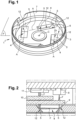
- FIG 1 is a representation of a part of an optical encoder, referenced 1, which corresponds to the part of the optical encoder receiving the reflection means, referenced 2.
- Part 1 is configured in a circular volume open at the top when looking at the figure 1 . This upper opening allows the other constituent elements of an optical encoder to be received, as schematically illustrated in the figure 2 .
- the bottom 3 of the part 1 is flat and, in the example, equipped with three rectangular through cutouts 4. Alternatively, the number of cutouts is other than three.
- the walls 5 of these cutouts 4 corresponding to the short sides of the rectangular cutouts 4 are inclined at 45° relative to the main plane P of the bottom 3. The inclination of the walls 5 is oriented so that the opening of the angle defined by the walls 5 is located on the internal face 6 of the bottom 3, therefore the face oriented towards the other constituent elements of the optical encoder when the latter are in place above the part 1.
- the main longitudinal axes A of the cutouts 4 are oriented angularly relative to each other. These cutouts 4 are distributed on the bottom 3, between the center C of the bottom 3 and the peripheral wall 7 limiting the bottom 3. Thus, the cutouts 4 and the inclined walls 5 define the reflection means 2. In a variant not illustrated, the number, arrangement, shape and dimensions of the cutouts 4 are different.
- FIG. 2 schematically represents the operation of such an optical encoder and, in particular, the role of the reflection means 2.
- a light-emitting diode 8 emits, advantageously in the infrared, a light beam F which passes through a glass reticle 9 before striking one of the walls 5 which deflects it and sends it back onto the other wall 5 of a cutout 4, in a direction parallel to the plane P of the bottom 3, due to the 45° inclination.
- the beam F passes back through the glass reticle 9 and through a glass disk 10 before striking photoreceptors 11.
- the disk 10 is rotatable, with opaque areas and translucent areas.
- the glass reticle 9 ensures the diffraction of the beam F.
- a detailed operation of this type of optical encoder is, for example, provided by EP-B-964 226 .
- FIG. 2 illustrates the role of the walls 5 which ensure the reflection in defined directions of the optical beam F.
- Such a generally U-shaped path of the beam F makes it possible to position the emitter 8 and the receiver 11 of the light beam F on the same plane in the optical encoder, which allows a gain in the total size of the encoder, in particular in thickness.
- the reflection of the beam F between the walls 5 must be done, in a constant manner, without any optical loss and by precisely respecting the parallelism of the optical paths of the beam F between the emitter 8 and one wall 5 and between the other wall 5 and the receiver 11, to guarantee the accuracy of the measurement.
- the characteristics of the reflection must be constant over time, without alteration or modification, regardless of the number of measurements carried out, the environmental conditions such as, for example, thermal differences, vibrations, shocks and this over the entire lifespan of an optical encoder knowing that this lifespan is at least 20 years.
- each wall 5 is thus provided with a reflective coating 12.
- This coating 12 is particularly visible at figure 3 .
- the coating 12 comprises a flat glass lamella 13.
- Such a lamella 13 has a thickness of between 0.15 mm and 0.25 mm, advantageously close to 0.2 mm. Since the inclined planes are machined with an optimal angle to achieve the path of the light beam, the coating must have a minimal impact on the initial reflection, therefore a minimal thickness in order to limit the optical imperfections of reflection, while being sufficiently strong and rigid. As a result, a thickness of the glass lamella close to 0.2 mm is retained.
- a lower face 14, looking at the figure 3 , of the strip 13 is adapted to be fixed on a wall 5.
- the fixing is done by gluing, advantageously with a glue that can be polymerized under ultraviolet light.
- a glue that can be polymerized under ultraviolet light.
- a glue must be fluid to be used in a thin layer so as not to affect the total thickness of the coating.
- This glue must withstand shocks, vibrations, large temperature ranges, for example from -40°C to +150°C, be durable over time given the lifespan of an encoder which is at least 20 years and be sufficiently flexible to accommodate the different thermal expansions between the glass of the strip and the metal of the inclined wall.
- the polymerization of the glue must be almost immediate, typically of the order of 15 s once the strip is in position and the user wishes to carry out the gluing.
- a glue is, for example, a transparent acrylic-based glue marketed by the company PANACOL.
- another glue is used, for example one that is heat-curable at ambient temperatures, generally between 20°C and 25°C.
- Face 15, opposite face 14, is schematically represented in figure 3 by hatching, for greater readability.
- the face 15 receives a layer of a material 16 having physicochemical characteristics such that it adheres, on the one hand, perfectly to the glass and, on the other hand, that it adheres to another material or to a mixture or alloy of materials having a reflection coefficient greater than 96% for the wavelengths concerned, namely in this case wavelengths between 800 nm and 900 nm.
- the material 16 is chromium.
- it is a material or an alloy of materials allowing adhesion to glass and also exhibiting adhesion to gold.
- material 16 here chromium, is chosen not only as having optimum adhesion to the glass but also as a function of material 17 chosen for its high reflection coefficient.
- material 17 is 99.99% pure gold whose reflection coefficient at 850 nm is 97.8%.
- the chromium 16 layer is fixed on the face 15 by techniques known per se, for example by deposition under evaporation. Such a technique makes it possible to produce a chromium 16 layer of between 0.05 micron and 0.1 micron.
- the gold layer 17 is also deposited using this technique and it also has a thickness of between 0.05 microns and 0.1 microns.
- the cumulative thicknesses of the lamella 13, the chromium layers 16 and gold 17 are of the order of 0.2 mm, which does not significantly modify the thickness of the walls 5 and therefore the path of the beam F.
- Gold is chosen to produce the layer of reflective material 17 because, in addition to a high reflection coefficient, namely greater than 96% for wavelengths between 800 nm and 900 nm, therefore in the infrared, this metal is inert, almost insensitive to corrosion, totally non-magnetic, ductile, malleable and easily polishable. It is used to obtain a flat, reflective, regular, homogeneous surface, while preserving the initial flatness, close to mirror polish, of glass. Because gold is a malleable and soft metal at room temperature, a layer 17 of gold is all the more sensitive to marking and shocks as it is thin. A patination phenomenon is also observed over time.
- the gold layer 17 is coated with a layer of a protective material 18.
- a layer of alumina with a thickness of around 0.015 mm is deposited on the layer 17.
- Such a thickness of the protective layer 18 ensures optimum protection without affecting the nominal thickness of the coating.
- it is another material or a composite material, for example silica, which can be used to protect, for example, other deposits of a material other than gold, for example silver-based deposits.
- the dimensions of the coating 12, therefore of the glass strip 13 coated with the chromium layer 16, the gold layer 17 and the protective layer 18 are generally between 2.5 mm and 3 mm wide by 2.5 mm to 3 mm long with a thickness of less than 0.3 mm.
- the coatings 12 are produced prior to the implementation of the invention by pre-cutting in a sheet 19 which defines a means of storing and transporting the coatings 12.
- This sheet 19 is obtained from a sheet of polymers on which, by techniques known per se such as deposition by evaporation, the different layers 13, 16 to 18 constituting the coating 12 are deposited. By sawing, each coating 12 is then pre-cut to the desired dimensions.
- the pre-cut coatings 12 are arranged in parallel rows.
- the arrangement of the coatings 12 on the sheet 19 is different.
- Such sheets 19 are produced beforehand, by techniques known per se from specialized suppliers.
- the fixing is carried out by gluing, advantageously with polymerization of the glue under UV.
- another type of glue is used, for example, a glue polymerizable at room temperature, in the presence or absence of an activator.
- the coating 12 is positioned on the wall 5, during the bonding fixing step, so that it covers the entire surface of the wall 5. Thus, when the beam F strikes the reflective layer 17, even if the beam F is not perfectly in the center of the reflective layer 17, this does not affect the optical path of the beam F towards the other wall 5.
- the reflective coating having a reflection coefficient of at least 96% at the wavelengths considered is obtained by machining, polishing the material constituting the walls 5.
- said walls 5 are, for example, made of another metal or metal alloy or material having similar optical properties.
- the material having a reflection coefficient greater than 96% is gold or a gold alloy of expansion similar to that of glass. ;
Landscapes
- Physics & Mathematics (AREA)
- General Physics & Mathematics (AREA)
- Optics & Photonics (AREA)
- Optical Transform (AREA)
Claims (5)
- Reflektierende Beschichtung (12) der Reflexionsmittel (2) eines Lichtstrahls (F), der von einer Lichtquelle (8) eines optischen Codierers emittiert wird, wobei die Reflexion des Lichtstrahls (F) auf einen Photorezeptor (11) gerichtet ist, dadurch gekennzeichnet, dass die Beschichtung (12) mindestens eine ebene Lamelle (13) aus Glas umfasst, die die Beschichtung bildet, deren eine Fläche (14) ein Verbindungsmittel auf einem Teil (5) des Reflexionsmittels (2) des optischen Codierers bildet, wobei die Lamelle auf der Fläche (15), die der Fläche (14) gegenüberliegt, die ein Verbindungsmittel bildet, mit mindestens einer Schicht (17) aus Gold oder einer Legierung auf Goldbasis beschichtet ist, die einen Reflexionskoeffizienten von mehr als 96 % für die Wellenlängen des Lichtstrahls (F) zwischen 800 nm und 900 nm aufweist, wobei die Lamelle (13) eine Nenndicke zwischen 0,15 mm und 0,25 mm aufweist, und dadurch, dass sie eine Schicht aus Schutzmaterial (18) der Goldschicht (17) umfasst, wobei das Schutzmaterial transparent, optisch neutral ist und die Nenndicke der Lamelle (13), die mit Gold (17) beschichtet ist, nicht beeinflusst.
- Beschichtung nach Anspruch 1, dadurch gekennzeichnet, dass die Fläche (15), die der Fläche (14) gegenüberliegt, die ein Verbindungsmittel bildet, eine Schicht aus einem Material (16) mit physikalisch-chemischen Eigenschaften erhält, die derart sind, dass es einerseits an der Fläche (15) aus Glas haftet und andererseits an einem anderen Material (17) oder an einer Mischung oder Legierung von Materialien haftet, die einen Reflexionskoeffizienten von mehr als 96 % für die Wellenlängen des zu reflektierenden Lichtstrahls (F) aufweisen.
- Beschichtung nach Anspruch 2, dadurch gekennzeichnet, dass das Material (16), das die Verbindung zwischen der Fläche (15) und dem reflektierenden Material (17) sicherstellt, Chrom oder eine Chromlegierung ist.
- Beschichtung nach Anspruch 2, dadurch gekennzeichnet, dass die Glaslamelle (13) und die Materialschichten (16 bis 18) auf einem Träger befestigt sind, der durch eine Polymerfolie (19) gebildet ist.
- Optischer Codierer, der mit mindestens einem Reflexionsmittel (2) nach einem der Ansprüche 1 bis 4 ausgestattet ist.
Applications Claiming Priority (2)
| Application Number | Priority Date | Filing Date | Title |
|---|---|---|---|
| FR2006885A FR3111979B1 (fr) | 2020-06-30 | 2020-06-30 | Revetement reflechissant des moyens de reflexion d’un codeur optique et codeur optique ainsi realise |
| PCT/IB2021/055409 WO2022003473A1 (fr) | 2020-06-30 | 2021-06-18 | Revetement reflechissant des moyens de reflexion d'un codeur optique et codeur optique ainsi realise |
Publications (3)
| Publication Number | Publication Date |
|---|---|
| EP4150302A1 EP4150302A1 (de) | 2023-03-22 |
| EP4150302B1 true EP4150302B1 (de) | 2024-11-06 |
| EP4150302C0 EP4150302C0 (de) | 2024-11-06 |
Family
ID=73013560
Family Applications (1)
| Application Number | Title | Priority Date | Filing Date |
|---|---|---|---|
| EP21733222.0A Active EP4150302B1 (de) | 2020-06-30 | 2021-06-18 | Reflektierende beschichtung für reflexionsmittel eines optischen codierers und so hergestellter optischer codierer |
Country Status (6)
| Country | Link |
|---|---|
| US (1) | US11959782B2 (de) |
| EP (1) | EP4150302B1 (de) |
| KR (1) | KR102927963B1 (de) |
| ES (1) | ES2994674T3 (de) |
| FR (1) | FR3111979B1 (de) |
| WO (1) | WO2022003473A1 (de) |
Citations (2)
| Publication number | Priority date | Publication date | Assignee | Title |
|---|---|---|---|---|
| EP0918236A1 (de) * | 1997-11-19 | 1999-05-26 | Alusuisse Technology & Management AG | Reflektor mit resistenter Oberfläche |
| EP2006712B1 (de) * | 2007-06-19 | 2010-05-12 | Mitutoyo Corporation | Maßstab für einen Oberflächenreflexionsgeber |
Family Cites Families (9)
| Publication number | Priority date | Publication date | Assignee | Title |
|---|---|---|---|---|
| US4998239A (en) * | 1987-10-07 | 1991-03-05 | The Dow Chemical Company | Optical information recording medium containing a metal alloy as a reflective material |
| US5336884A (en) * | 1992-07-01 | 1994-08-09 | Rockwell International Corporation | High resolution optical hybrid absolute incremental position encoder |
| FR2779816B1 (fr) | 1998-06-10 | 2001-04-13 | Codechamp | Codeur optique |
| EP1154289A1 (de) * | 2000-05-09 | 2001-11-14 | Alcan Technology & Management AG | Reflektor |
| US20130221212A1 (en) * | 2012-02-24 | 2013-08-29 | Avago Technologies Ecbu Ip (Singapore) Pte. Ltd. | Coding Members With Embedded Metal Layers For Encoders |
| US10315951B2 (en) * | 2015-06-17 | 2019-06-11 | The Board Of Trustees Of The University Of Illinois | Bowtie nanoantennas and methods of using the same |
| EP3563118B1 (de) * | 2016-12-28 | 2024-10-16 | Michael Naor | System und verfahren zur optischen codierung |
| JP2018185210A (ja) * | 2017-04-25 | 2018-11-22 | セイコーエプソン株式会社 | エンコーダー、プリンターおよびロボット |
| EP4707746A2 (de) * | 2020-03-31 | 2026-03-11 | Dai Nippon Printing Co., Ltd. | Optische kodierskala vom reflexionstyp und optischer kodierer vom reflexionstyp |
-
2020
- 2020-06-30 FR FR2006885A patent/FR3111979B1/fr active Active
-
2021
- 2021-06-18 US US18/009,782 patent/US11959782B2/en active Active
- 2021-06-18 KR KR1020227044760A patent/KR102927963B1/ko active Active
- 2021-06-18 WO PCT/IB2021/055409 patent/WO2022003473A1/fr not_active Ceased
- 2021-06-18 EP EP21733222.0A patent/EP4150302B1/de active Active
- 2021-06-18 ES ES21733222T patent/ES2994674T3/es active Active
Patent Citations (2)
| Publication number | Priority date | Publication date | Assignee | Title |
|---|---|---|---|---|
| EP0918236A1 (de) * | 1997-11-19 | 1999-05-26 | Alusuisse Technology & Management AG | Reflektor mit resistenter Oberfläche |
| EP2006712B1 (de) * | 2007-06-19 | 2010-05-12 | Mitutoyo Corporation | Maßstab für einen Oberflächenreflexionsgeber |
Also Published As
| Publication number | Publication date |
|---|---|
| KR20230011427A (ko) | 2023-01-20 |
| EP4150302A1 (de) | 2023-03-22 |
| ES2994674T3 (en) | 2025-01-29 |
| US11959782B2 (en) | 2024-04-16 |
| FR3111979B1 (fr) | 2023-03-24 |
| KR102927963B1 (ko) | 2026-02-13 |
| EP4150302C0 (de) | 2024-11-06 |
| FR3111979A1 (fr) | 2021-12-31 |
| US20230314186A1 (en) | 2023-10-05 |
| WO2022003473A1 (fr) | 2022-01-06 |
Similar Documents
| Publication | Publication Date | Title |
|---|---|---|
| US6839173B2 (en) | Reflection type diffraction grating | |
| FR2487101A1 (fr) | Support d'enregistrement et de memorisation optique de donnees | |
| EP1910805B1 (de) | Optisches refraktometer zur messung des salzgehalts von meerwasser und entsprechender salzgehaltsensor | |
| FR3016214A1 (fr) | Detecteur optique d'un gaz | |
| EP4150302B1 (de) | Reflektierende beschichtung für reflexionsmittel eines optischen codierers und so hergestellter optischer codierer | |
| EP0466598B1 (de) | Verfahren und Einrichtung zur Ablagerung von Antireflektionsschichten und zur Kontrolle ihrer Dicke | |
| US6885455B2 (en) | Self-calibration of an optical-based sensor using a total internal reflection (TIR) signature | |
| US5923464A (en) | Substance for front surface mirror | |
| FR2499245A1 (fr) | Dispositif a fluorescence de rayons x | |
| JP4311739B2 (ja) | 干渉計装置用光量比調整フィルタ、干渉計装置および光干渉測定方法 | |
| FR3052923A1 (fr) | Reflecteur optique resonant a multiples couches minces de materiaux dielectriques, capteur optique et dispositif d'amplification laser comportant un tel reflecteur | |
| EP0331581B1 (de) | Piezoelektrischer Spiegel für Laserkreisel | |
| EP4075182A1 (de) | Optischer scanner | |
| WO2004065946A1 (fr) | Micro-composant étalon pour le calibrage ou l'étalonnage d'équipements de mesure de fluorescence et biopuce le comportant. | |
| EP3431964B1 (de) | Optischer hohlraum mit starker dynamik | |
| JP2653066B2 (ja) | 光ビーム偏向走査装置 | |
| WO1997023789A1 (fr) | Rejecteur spectral grand champ angulaire et procede de fabrication | |
| JP3578620B2 (ja) | 光学定数測定方法及び光学定数測定装置 | |
| EP1749187A1 (de) | Interferometereinrichtung zur kontinuierlichen messung der dicke dünner transparenter schichten auf einem substrat | |
| EP2145331A1 (de) | Verfahren und system zum lesen optischer informationen mit hoher dichte | |
| WO2025233055A1 (en) | Support for a dark field optical inspection system | |
| FR2467460A1 (fr) | Videodisque optique pour l'enregistrement et la lecture a deux longueurs d'onde differentes | |
| EP4553561A1 (de) | Reflektorvorrichtung mit einem detektor und verfahren dafür | |
| WO2025219683A1 (fr) | Mire de calibration pour capteur optique | |
| FR2671657A1 (fr) | Disque optique ou matrice de pressage pour la fabrication de tels disques. |
Legal Events
| Date | Code | Title | Description |
|---|---|---|---|
| STAA | Information on the status of an ep patent application or granted ep patent |
Free format text: STATUS: UNKNOWN |
|
| STAA | Information on the status of an ep patent application or granted ep patent |
Free format text: STATUS: THE INTERNATIONAL PUBLICATION HAS BEEN MADE |
|
| PUAI | Public reference made under article 153(3) epc to a published international application that has entered the european phase |
Free format text: ORIGINAL CODE: 0009012 |
|
| STAA | Information on the status of an ep patent application or granted ep patent |
Free format text: STATUS: REQUEST FOR EXAMINATION WAS MADE |
|
| 17P | Request for examination filed |
Effective date: 20221206 |
|
| AK | Designated contracting states |
Kind code of ref document: A1 Designated state(s): AL AT BE BG CH CY CZ DE DK EE ES FI FR GB GR HR HU IE IS IT LI LT LU LV MC MK MT NL NO PL PT RO RS SE SI SK SM TR |
|
| DAV | Request for validation of the european patent (deleted) | ||
| DAX | Request for extension of the european patent (deleted) | ||
| STAA | Information on the status of an ep patent application or granted ep patent |
Free format text: STATUS: EXAMINATION IS IN PROGRESS |
|
| 17Q | First examination report despatched |
Effective date: 20240102 |
|
| GRAP | Despatch of communication of intention to grant a patent |
Free format text: ORIGINAL CODE: EPIDOSNIGR1 |
|
| STAA | Information on the status of an ep patent application or granted ep patent |
Free format text: STATUS: GRANT OF PATENT IS INTENDED |
|
| INTG | Intention to grant announced |
Effective date: 20240710 |
|
| GRAS | Grant fee paid |
Free format text: ORIGINAL CODE: EPIDOSNIGR3 |
|
| GRAA | (expected) grant |
Free format text: ORIGINAL CODE: 0009210 |
|
| STAA | Information on the status of an ep patent application or granted ep patent |
Free format text: STATUS: THE PATENT HAS BEEN GRANTED |
|
| AK | Designated contracting states |
Kind code of ref document: B1 Designated state(s): AL AT BE BG CH CY CZ DE DK EE ES FI FR GB GR HR HU IE IS IT LI LT LU LV MC MK MT NL NO PL PT RO RS SE SI SK SM TR |
|
| REG | Reference to a national code |
Ref country code: GB Ref legal event code: FG4D Free format text: NOT ENGLISH |
|
| REG | Reference to a national code |
Ref country code: CH Ref legal event code: EP |
|
| REG | Reference to a national code |
Ref country code: DE Ref legal event code: R096 Ref document number: 602021021425 Country of ref document: DE |
|
| REG | Reference to a national code |
Ref country code: IE Ref legal event code: FG4D Free format text: LANGUAGE OF EP DOCUMENT: FRENCH |
|
| U01 | Request for unitary effect filed |
Effective date: 20241121 |
|
| U07 | Unitary effect registered |
Designated state(s): AT BE BG DE DK EE FI FR IT LT LU LV MT NL PT RO SE SI Effective date: 20241127 |
|
| REG | Reference to a national code |
Ref country code: ES Ref legal event code: FG2A Ref document number: 2994674 Country of ref document: ES Kind code of ref document: T3 Effective date: 20250129 |
|
| PG25 | Lapsed in a contracting state [announced via postgrant information from national office to epo] |
Ref country code: HR Free format text: LAPSE BECAUSE OF FAILURE TO SUBMIT A TRANSLATION OF THE DESCRIPTION OR TO PAY THE FEE WITHIN THE PRESCRIBED TIME-LIMIT Effective date: 20241106 Ref country code: IS Free format text: LAPSE BECAUSE OF FAILURE TO SUBMIT A TRANSLATION OF THE DESCRIPTION OR TO PAY THE FEE WITHIN THE PRESCRIBED TIME-LIMIT Effective date: 20250306 |
|
| PG25 | Lapsed in a contracting state [announced via postgrant information from national office to epo] |
Ref country code: NO Free format text: LAPSE BECAUSE OF FAILURE TO SUBMIT A TRANSLATION OF THE DESCRIPTION OR TO PAY THE FEE WITHIN THE PRESCRIBED TIME-LIMIT Effective date: 20250206 |
|
| PG25 | Lapsed in a contracting state [announced via postgrant information from national office to epo] |
Ref country code: GR Free format text: LAPSE BECAUSE OF FAILURE TO SUBMIT A TRANSLATION OF THE DESCRIPTION OR TO PAY THE FEE WITHIN THE PRESCRIBED TIME-LIMIT Effective date: 20250207 |
|
| PG25 | Lapsed in a contracting state [announced via postgrant information from national office to epo] |
Ref country code: PL Free format text: LAPSE BECAUSE OF FAILURE TO SUBMIT A TRANSLATION OF THE DESCRIPTION OR TO PAY THE FEE WITHIN THE PRESCRIBED TIME-LIMIT Effective date: 20241106 |
|
| PG25 | Lapsed in a contracting state [announced via postgrant information from national office to epo] |
Ref country code: RS Free format text: LAPSE BECAUSE OF FAILURE TO SUBMIT A TRANSLATION OF THE DESCRIPTION OR TO PAY THE FEE WITHIN THE PRESCRIBED TIME-LIMIT Effective date: 20250206 |
|
| PG25 | Lapsed in a contracting state [announced via postgrant information from national office to epo] |
Ref country code: SM Free format text: LAPSE BECAUSE OF FAILURE TO SUBMIT A TRANSLATION OF THE DESCRIPTION OR TO PAY THE FEE WITHIN THE PRESCRIBED TIME-LIMIT Effective date: 20241106 |
|
| PGFP | Annual fee paid to national office [announced via postgrant information from national office to epo] |
Ref country code: MC Payment date: 20250624 Year of fee payment: 5 |
|
| PGFP | Annual fee paid to national office [announced via postgrant information from national office to epo] |
Ref country code: GB Payment date: 20250618 Year of fee payment: 5 |
|
| PG25 | Lapsed in a contracting state [announced via postgrant information from national office to epo] |
Ref country code: SK Free format text: LAPSE BECAUSE OF FAILURE TO SUBMIT A TRANSLATION OF THE DESCRIPTION OR TO PAY THE FEE WITHIN THE PRESCRIBED TIME-LIMIT Effective date: 20241106 |
|
| PG25 | Lapsed in a contracting state [announced via postgrant information from national office to epo] |
Ref country code: CZ Free format text: LAPSE BECAUSE OF FAILURE TO SUBMIT A TRANSLATION OF THE DESCRIPTION OR TO PAY THE FEE WITHIN THE PRESCRIBED TIME-LIMIT Effective date: 20241106 |
|
| U20 | Renewal fee for the european patent with unitary effect paid |
Year of fee payment: 5 Effective date: 20250627 |
|
| PLBE | No opposition filed within time limit |
Free format text: ORIGINAL CODE: 0009261 |
|
| STAA | Information on the status of an ep patent application or granted ep patent |
Free format text: STATUS: NO OPPOSITION FILED WITHIN TIME LIMIT |
|
| PGFP | Annual fee paid to national office [announced via postgrant information from national office to epo] |
Ref country code: ES Payment date: 20250731 Year of fee payment: 5 |
|
| 26N | No opposition filed |
Effective date: 20250807 |
|
| REG | Reference to a national code |
Ref country code: CH Ref legal event code: H13 Free format text: ST27 STATUS EVENT CODE: U-0-0-H10-H13 (AS PROVIDED BY THE NATIONAL OFFICE) Effective date: 20260127 |
|
| PG25 | Lapsed in a contracting state [announced via postgrant information from national office to epo] |
Ref country code: IE Free format text: LAPSE BECAUSE OF NON-PAYMENT OF DUE FEES Effective date: 20250618 |
|
| PG25 | Lapsed in a contracting state [announced via postgrant information from national office to epo] |
Ref country code: CH Free format text: LAPSE BECAUSE OF NON-PAYMENT OF DUE FEES Effective date: 20250630 |