EP4151435B1 - Reifen - Google Patents
Reifen Download PDFInfo
- Publication number
- EP4151435B1 EP4151435B1 EP22190100.2A EP22190100A EP4151435B1 EP 4151435 B1 EP4151435 B1 EP 4151435B1 EP 22190100 A EP22190100 A EP 22190100A EP 4151435 B1 EP4151435 B1 EP 4151435B1
- Authority
- EP
- European Patent Office
- Prior art keywords
- tire
- shoulder
- sipe
- axial direction
- land portion
- Prior art date
- Legal status (The legal status is an assumption and is not a legal conclusion. Google has not performed a legal analysis and makes no representation as to the accuracy of the status listed.)
- Active
Links
Images




Classifications
-
- B—PERFORMING OPERATIONS; TRANSPORTING
- B60—VEHICLES IN GENERAL
- B60C—VEHICLE TYRES; TYRE INFLATION; TYRE CHANGING; CONNECTING VALVES TO INFLATABLE ELASTIC BODIES IN GENERAL; DEVICES OR ARRANGEMENTS RELATED TO TYRES
- B60C11/00—Tyre tread bands; Tread patterns; Anti-skid inserts
- B60C11/03—Tread patterns
- B60C11/04—Tread patterns in which the raised area of the pattern consists only of continuous circumferential ribs, e.g. zig-zag
-
- B—PERFORMING OPERATIONS; TRANSPORTING
- B60—VEHICLES IN GENERAL
- B60C—VEHICLE TYRES; TYRE INFLATION; TYRE CHANGING; CONNECTING VALVES TO INFLATABLE ELASTIC BODIES IN GENERAL; DEVICES OR ARRANGEMENTS RELATED TO TYRES
- B60C11/00—Tyre tread bands; Tread patterns; Anti-skid inserts
- B60C11/03—Tread patterns
- B60C11/12—Tread patterns characterised by the use of narrow slits or incisions, e.g. sipes
- B60C11/1204—Tread patterns characterised by the use of narrow slits or incisions, e.g. sipes with special shape of the sipe
-
- B—PERFORMING OPERATIONS; TRANSPORTING
- B60—VEHICLES IN GENERAL
- B60C—VEHICLE TYRES; TYRE INFLATION; TYRE CHANGING; CONNECTING VALVES TO INFLATABLE ELASTIC BODIES IN GENERAL; DEVICES OR ARRANGEMENTS RELATED TO TYRES
- B60C11/00—Tyre tread bands; Tread patterns; Anti-skid inserts
- B60C11/03—Tread patterns
- B60C11/12—Tread patterns characterised by the use of narrow slits or incisions, e.g. sipes
- B60C11/1236—Tread patterns characterised by the use of narrow slits or incisions, e.g. sipes with special arrangements in the tread pattern
-
- B—PERFORMING OPERATIONS; TRANSPORTING
- B60—VEHICLES IN GENERAL
- B60C—VEHICLE TYRES; TYRE INFLATION; TYRE CHANGING; CONNECTING VALVES TO INFLATABLE ELASTIC BODIES IN GENERAL; DEVICES OR ARRANGEMENTS RELATED TO TYRES
- B60C11/00—Tyre tread bands; Tread patterns; Anti-skid inserts
- B60C11/03—Tread patterns
- B60C11/12—Tread patterns characterised by the use of narrow slits or incisions, e.g. sipes
- B60C11/1272—Width of the sipe
- B60C11/1281—Width of the sipe different within the same sipe, i.e. enlarged width portion at sipe bottom or along its length
-
- B—PERFORMING OPERATIONS; TRANSPORTING
- B60—VEHICLES IN GENERAL
- B60C—VEHICLE TYRES; TYRE INFLATION; TYRE CHANGING; CONNECTING VALVES TO INFLATABLE ELASTIC BODIES IN GENERAL; DEVICES OR ARRANGEMENTS RELATED TO TYRES
- B60C11/00—Tyre tread bands; Tread patterns; Anti-skid inserts
- B60C11/03—Tread patterns
- B60C11/0304—Asymmetric patterns
-
- B—PERFORMING OPERATIONS; TRANSPORTING
- B60—VEHICLES IN GENERAL
- B60C—VEHICLE TYRES; TYRE INFLATION; TYRE CHANGING; CONNECTING VALVES TO INFLATABLE ELASTIC BODIES IN GENERAL; DEVICES OR ARRANGEMENTS RELATED TO TYRES
- B60C11/00—Tyre tread bands; Tread patterns; Anti-skid inserts
- B60C11/03—Tread patterns
- B60C2011/0337—Tread patterns characterised by particular design features of the pattern
- B60C2011/0339—Grooves
- B60C2011/0341—Circumferential grooves
- B60C2011/0353—Circumferential grooves characterised by width
-
- B—PERFORMING OPERATIONS; TRANSPORTING
- B60—VEHICLES IN GENERAL
- B60C—VEHICLE TYRES; TYRE INFLATION; TYRE CHANGING; CONNECTING VALVES TO INFLATABLE ELASTIC BODIES IN GENERAL; DEVICES OR ARRANGEMENTS RELATED TO TYRES
- B60C11/00—Tyre tread bands; Tread patterns; Anti-skid inserts
- B60C11/03—Tread patterns
- B60C2011/0337—Tread patterns characterised by particular design features of the pattern
- B60C2011/0339—Grooves
- B60C2011/0358—Lateral grooves, i.e. having an angle of 45 to 90 degees to the equatorial plane
- B60C2011/036—Narrow grooves, i.e. having a width of less than 3 mm
-
- B—PERFORMING OPERATIONS; TRANSPORTING
- B60—VEHICLES IN GENERAL
- B60C—VEHICLE TYRES; TYRE INFLATION; TYRE CHANGING; CONNECTING VALVES TO INFLATABLE ELASTIC BODIES IN GENERAL; DEVICES OR ARRANGEMENTS RELATED TO TYRES
- B60C11/00—Tyre tread bands; Tread patterns; Anti-skid inserts
- B60C11/03—Tread patterns
- B60C2011/0337—Tread patterns characterised by particular design features of the pattern
- B60C2011/0386—Continuous ribs
- B60C2011/0388—Continuous ribs provided at the equatorial plane
-
- B—PERFORMING OPERATIONS; TRANSPORTING
- B60—VEHICLES IN GENERAL
- B60C—VEHICLE TYRES; TYRE INFLATION; TYRE CHANGING; CONNECTING VALVES TO INFLATABLE ELASTIC BODIES IN GENERAL; DEVICES OR ARRANGEMENTS RELATED TO TYRES
- B60C11/00—Tyre tread bands; Tread patterns; Anti-skid inserts
- B60C11/03—Tread patterns
- B60C11/12—Tread patterns characterised by the use of narrow slits or incisions, e.g. sipes
- B60C11/1204—Tread patterns characterised by the use of narrow slits or incisions, e.g. sipes with special shape of the sipe
- B60C2011/1209—Tread patterns characterised by the use of narrow slits or incisions, e.g. sipes with special shape of the sipe straight at the tread surface
-
- Y—GENERAL TAGGING OF NEW TECHNOLOGICAL DEVELOPMENTS; GENERAL TAGGING OF CROSS-SECTIONAL TECHNOLOGIES SPANNING OVER SEVERAL SECTIONS OF THE IPC; TECHNICAL SUBJECTS COVERED BY FORMER USPC CROSS-REFERENCE ART COLLECTIONS [XRACs] AND DIGESTS
- Y02—TECHNOLOGIES OR APPLICATIONS FOR MITIGATION OR ADAPTATION AGAINST CLIMATE CHANGE
- Y02T—CLIMATE CHANGE MITIGATION TECHNOLOGIES RELATED TO TRANSPORTATION
- Y02T10/00—Road transport of goods or passengers
- Y02T10/80—Technologies aiming to reduce greenhouse gasses emissions common to all road transportation technologies
- Y02T10/86—Optimisation of rolling resistance, e.g. weight reduction
Definitions
- the present invention relates to a tire.
- a tire in accordance with the preamble of claim 1 is known from JP H02 53609 A .
- Related tires are described in JP 2009 298262 A , JP H05 338418 A , JP S60 255506 A and EP 3 088 213 A1 .
- the present invention has been made in view of the above circumstances, and a main object of the present invention is to provide a 5-rib tire that can have improved steering stability and noise performance.
- the present invention is directed to a tire including a tread portion, wherein: the tread portion includes four circumferential grooves continuously extending in a tire circumferential direction between two tread ends, wherein a first tread end and a second tread end correspond to ends of a 50%-load ground-contact surface obtained when 50% of a normal load is applied to the tire in a normal state and the tread portion is brought into contact with a flat surface at a camber angle of 0°, and five land portions demarcated by the four circumferential grooves; each of the five land portions is provided with no groove having a groove width greater than 2.0 mm, and is provided with only sipes; the four circumferential grooves include a shoulder circumferential groove provided closest to the tread end; the five land portions include a shoulder land portion including the tread end, and a middle land portion adjacent to the shoulder land portion via the shoulder circumferential groove; the middle land portion is provided with a plurality of middle sipes fully traversing the middle land portion in a tire axial direction so as to be inclined relative to the
- the tire has a designated mounting direction to a vehicle.
- the shoulder land portion includes a first shoulder land portion located on an outer side of the vehicle when the tire is mounted on the vehicle, and a second shoulder land portion located on an inner side of the vehicle when the tire is mounted on the vehicle.
- the middle land portion includes a first middle land portion located on the outer side of the vehicle when the tire is mounted on the vehicle, and a second middle land portion located on the inner side of the vehicle when the tire is mounted on the vehicle.
- the five land portions include a crown land portion provided between the first middle land portion and the second middle land portion.
- a width of a ground-contact surface of the first shoulder land portion is larger than a width of a ground-contact surface of the second shoulder land portion
- a width of a ground-contact surface of the first middle land portion is larger than a width of a ground-contact surface of the second middle land portion.
- the tire of the present invention can have improved steering stability and noise performance.
- the shoulder sipe includes an axial portion having an angle with respect to the tire axial direction smaller than that of the inclined portion and not greater than 10°, and a curved portion extending so as to be curved between the inclined portion and the axial portion.
- At least one of sipe edges on both sides of the middle sipe is formed as a chamfered portion, and in a tread plan view, a width of the chamfered portion of the middle sipe increases toward a tire equator side.
- At least one of the sipe edges on both sides of the inclined portion is formed as a chamfered portion, and in a tread plan view, a maximum width of the chamfered portion of the middle sipe is larger than a maximum width of the chamfered portion of the inclined portion.
- the shoulder sipes include a first shoulder sipe provided on the first shoulder land portion, and a second shoulder sipe provided on the second shoulder land portion
- the middle sipes include a first middle sipe provided on the first middle land portion, and a second middle sipe provided on the second middle land portion, wherein a maximum angle of the inclined portion of the first shoulder sipe with respect to the tire axial direction is larger than a maximum angle of the inclined portion of the second shoulder sipe with respect to the tire axial direction, and wherein a maximum angle of the first middle sipe with respect to the tire axial direction is larger than a maximum angle of the second middle sipe with respect to the tire axial direction.
- the absolute value of a difference between the maximum angle of the second middle sipe with respect to the tire axial direction and the maximum angle of the inclined portion of the second shoulder sipe with respect to the tire axial direction is larger than the absolute value of a difference between the maximum angle of the first middle sipe with respect to the tire axial direction and the maximum angle of the inclined portion of the first shoulder sipe with respect to the tire axial direction.
- the crown land portion is provided with a plurality of first crown sipes and a plurality of second crown sipes inclined relative to the tire axial direction, wherein maximum angles of the first crown sipes and the second crown sipes with respect to the tire axial direction are not greater than the maximum angle of the first middle sipe with respect to the tire axial direction, and are not less than the maximum angle of the second middle sipe with respect to the tire axial direction.
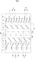
- FIG. 1 is a development of a tread portion 2 of a tire 1 showing the embodiment of the present invention.
- the tire 1 of the present embodiment of the invention is suitably used, for example, as a pneumatic tire for a passenger car.
- the present invention is not limited to such a mode, and may be applied to a heavy-duty pneumatic tire and a non-pneumatic tire the interior of which is not filled with pressurized air.
- the tread portion 2 of the present invention includes four circumferential grooves 3 continuously extending in the tire circumferential direction between two tread ends, and five land portions 4 demarcated by these circumferential grooves 3. That is, the tire 1 of the present invention is configured as a so-called 5-rib tire in which the tread portion 2 includes four circumferential grooves 3 and five land portions 4.
- one of two tread ends is sometimes referred to as a first tread end T1
- the other of the two tread ends is sometimes referred to as a second tread end T2.
- the tread portion 2 of the present embodiment of the invention has a designated mounting direction to a vehicle. Accordingly, the first tread end T1 is intended to be located on the outer side of the vehicle when the tire 1 is mounted on the vehicle. The second tread end T2 is intended to be located on the inner side of the vehicle when the tire 1 is mounted on the vehicle.
- the mounting direction to a vehicle is indicated, for example, by characters or marks on a sidewall portion (not shown).
- the first tread end T1 and the second tread end T2 correspond to ends of a 50%-load ground-contact surface obtained when 50% of a normal load is applied to the tire 1 in a normal state and the tread portion 2 is brought into contact with a flat surface at a camber angle of 0°.
- the "normal state” is a state where the tire is fitted on a normal rim and inflated to a normal internal pressure and no load is applied to the tire.
- the normal state means a standard use state, corresponding to the purpose of use of the tire, where the tire is not mounted on a vehicle and no load is applied to the tire.
- dimensions and the like of components of the tire are values measured in the normal state.
- the "normal rim” is a rim that is defined, in a standard system including a standard on which the tire is based, by the standard for each tire, and is, for example, the "standard rim” in the JATMA standard, the "Design Rim” in the TRA standard, or the “Measuring Rim” in the ETRTO standard.
- the "normal internal pressure” is an air pressure that is defined, in a standard system including a standard on which the tire is based, by the standard for each tire, and is the “maximum air pressure” in the JATMA standard, the maximum value indicated in the table "TIRE LOAD LIMITS AT VARIOUS COLD INFLATION PRESSURES" in the TRA standard, or the “INFLATION PRESSURE” in the ETRTO standard.
- the "normal load” is a load that is defined, in a standard system including a standard on which the tire is based, by the standard for each tire, and is the "maximum load capacity" in the JATMA standard, the maximum value indicated in the table "TIRE LOAD LIMITS AT VARIOUS COLD INFLATION PRESSURES" in the TRA standard, or the "LOAD CAPACITY” in the ETRTO standard.
- the "normal load” refers to the maximum load applicable when the tire is used, according to the above-described standards.
- the circumferential grooves 3 include two shoulder circumferential grooves 5 and 6, and two crown circumferential grooves 7 and 8 provided between the shoulder circumferential grooves 5 and 6.
- the shoulder circumferential groove provided on the first tread end T1 side is sometimes referred to as a first shoulder circumferential groove 5
- the shoulder circumferential groove provided on the second tread end T2 side is sometimes referred to as a second shoulder circumferential groove 6.
- the two crown circumferential grooves 7 and 8 are provided with a tire equator C therebetween.
- the crown circumferential groove provided between the first shoulder circumferential groove 5 and the tire equator C is sometimes referred to as a first crown circumferential groove 7
- the crown circumferential groove provided between the second shoulder circumferential groove 6 and the tire equator C is sometimes referred to as a second crown circumferential groove 8.
- a distance L1 in the tire axial direction from the tire equator C to a groove center line of the first shoulder circumferential groove 5 or the second shoulder circumferential groove 6 is preferably, for example, 20% to 30% of a tread width TW.
- a distance L2 in the tire axial direction from the tire equator C to a groove center line of the first crown circumferential groove 7 or the second crown circumferential groove 8 is preferably, for example, 5% to 15% of the tread width TW.
- the tread width TW is the distance in the tire axial direction from the first tread end T1 to the second tread end T2 in the normal state.
- Each circumferential groove 3 of the present embodiment of the invention may extend, for example, in a straight manner so as to be parallel to the tire circumferential direction.
- Each circumferential groove 3 may extend, for example, in a wavy manner.
- a groove width W1 of each circumferential groove 3 is preferably at least not less than 3 mm.
- the groove width W1 of each circumferential groove 3 is preferably, for example, 3.0% to 8.5% of the tread width TW.
- the first shoulder circumferential groove 5 has the smallest groove width among a plurality of the circumferential grooves 3.
- FIG. 2 is a cross-sectional view, of the tire 1 of the present embodiment of the invention, including the rotation axis of the tire 1.
- the depth of each circumferential groove 3 is, for example, 5 to 10 mm in the case of a pneumatic tire for a passenger car.
- the first shoulder circumferential groove 5 has the smallest depth among the four circumferential grooves 3.
- the first crown circumferential groove 7, the second crown circumferential groove 8, and the second shoulder circumferential groove 6 are each formed as a flat groove having a smaller depth than the groove width thereof.
- the present invention is not limited to such a mode.
- each land portion 4 demarcated in the tread portion 2 is provided with no groove having a groove width greater than 2.0 mm, and is provided with only sipes 9, in a ground-contact surface thereof.
- the groove means a groove in which, in a transverse cross-section thereof, a region where the distance between two groove walls is greater than 2.0 mm exceeds 50% of the total depth of the groove.
- the "sipe” means a small-width slit which has two inner walls extending in the tire radial direction and in which, in a transverse cross-section thereof, a region where the distance between the two inner walls is not greater than 2.0 mm is not less than 50% of the total depth of the slit.
- FIG. 3 shows a transverse cross-sectional view of a typical sipe 9 in the present embodiment of the invention.
- a width W2 between two sipe walls 9w extending so as to face and be substantially parallel to each other is preferably not greater than 1.5 mm, and is 0.4 to 1.0 mm in a more preferable mode.
- the total depth of the sipe 9 is, for example, 3.0 to 5.5 mm.
- At least one of sipe edges on both sides of the sipe 9 is formed, for example, as a chamfered portion 16.
- Each of the sipe edges on both sides of the sipe 9 of the present embodiment of the invention is formed as a chamfered portion 16.
- a sipe 9 is sometimes referred to as a chamfered sipe.
- the chamfered portion 16 is formed so as to include an inclined surface 17 connected to the ground-contact surface and the sipe wall 9w.
- An angle of the inclined surface 17 with respect to the depth direction of the sipe 9 is, for example, 30 to 60°.
- the depth of the chamfered portion 16 is, for example, less than 30% of the total depth of the sipe 9, specifically not greater than 2.0 mm, and more preferably not greater than 1.0 mm. If the chamfered portion 16 having such a depth is included, the opening width of the chamfered sipe may exceed 2.0 mm.
- each sipe 9 is not limited to the above-described mode. Therefore, the sipe 9 may extend with a uniform width from an opening in the ground-contact surface to a bottom portion thereof. In addition, a flask bottom having a width greater than 2.0 mm may be connected to the bottom portion of the sipe 9.
- the five land portions 4 of the present invention include at least one shoulder land portion including a tread end, and a middle land portion adjacent to the shoulder land portion.
- the five land portions 4 of the present embodiment of the invention include two shoulder land portions (a first shoulder land portion 11 and a second shoulder land portion 12), and two middle land portions (a first middle land portion 13 and a second middle land portion 14).
- the first shoulder land portion 11 includes the first tread end T1 and is demarcated outward of the first shoulder circumferential groove 5 in the tire axial direction.
- the second shoulder land portion 12 includes the second tread end T2 and is demarcated outward of the second shoulder circumferential groove 6 in the tire axial direction.
- the first middle land portion 13 is adjacent to the first shoulder land portion 11 and is demarcated between the first shoulder circumferential groove 5 and the first crown circumferential groove 7.
- the second middle land portion 14 is adjacent to the second shoulder land portion 12 and is demarcated between the second shoulder circumferential groove 6 and the second crown circumferential groove 8.
- the five land portions 4 further includes a crown land portion 15.
- the crown land portion 15 is demarcated between the first crown circumferential groove 7 and the second crown circumferential groove 8.
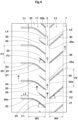
- FIG. 4 shows an enlarged view of the first shoulder land portion 11 and the first middle land portion 13.
- the middle land portion is provided with a plurality of middle sipes fully traversing the middle land portion in the tire axial direction so as to be inclined relative to the tire axial direction.
- the shoulder land portion is provided with a plurality of shoulder sipes each extending from the shoulder circumferential groove to a position beyond the tread end.
- the first middle land portion 13 of the present embodiment of the invention is provided with a plurality of first middle sipes 30 fully traversing the first middle land portion 13 in the tire axial direction so as to be inclined relative to the tire axial direction.
- the first shoulder land portion 11 is provided with a plurality of first shoulder sipes 20 each extending from the first shoulder circumferential groove 5 to a position beyond the first tread end T1.
- At least one of the shoulder sipes includes an inclined portion 21 extending from the first shoulder circumferential groove 5 so as to be inclined relative to the tire axial direction.
- Each middle sipe (first middle sipe 30) is inclined relative to the tire axial direction in a direction opposite to that of the inclined portion 21.
- a maximum angle ⁇ 1 of the inclined portion 21 with respect to the tire axial direction is not greater than a maximum angle ⁇ 2 of the middle sipe (first middle sipe 30) with respect to the tire axial direction.
- the difference between the maximum angle ⁇ 1 of the inclined portion 21 and the maximum angle ⁇ 2 of the first middle sipe 30 is not greater than 5°.
- the angle ⁇ 1 and the angle ⁇ 2 are each the absolute value of the acute angle formed between the sipe and a virtual line extending parallel to the tire axial direction, and the difference therebetween means the value obtained by subtracting the absolute value of the angle ⁇ 1 from the absolute value of the angle ⁇ 2.
- each land portion 4 is provided with no groove having a groove width greater than 2.0 mm, and is provided with only sipes 9, pattern noise is low and excellent noise performance is exhibited.
- such a land portion 4 has high pattern stiffness and serves to improve steering stability.
- first shoulder sipes 20 include the inclined portions 21, the entire edges of the first shoulder sipes 20 can each come into contact with the ground with a time difference, so that sounds can be reduced when these edges come into contact with the ground.
- the angle ⁇ 1 of the inclined portion 21 is not greater than the angle ⁇ 2 of the middle sipe (first middle sipe 30), and the difference between the angle ⁇ 1 and the angle ⁇ 2 is not greater than 5°.
- the stiffness in the tire axial direction of the first shoulder land portion 11 is equal to or slightly higher than that of the first middle land portion 13.
- Such a stiffness distribution can improve linearity and responsiveness during steering, and further, excellent steering stability is exhibited.
- noise performance and steering stability can be inferred to be improved by the above mechanism.
- a one-pitch length P1 in the tire circumferential direction of the plurality of first shoulder sipes 20 is, for example, 80% to 120% of a width W3 of the ground-contact surface of the first shoulder land portion 11.
- Such arrangement of the first shoulder sipes 20 serves to improve steering stability and noise performance in a well-balanced manner.
- the inclined portion 21 is inclined downward toward the right side relative to the tire axial direction.
- the direction of such inclination is sometimes referred to as "inclined in a first direction relative to the tire axial direction”.
- a maximum angle ⁇ 1 of the inclined portion 21 with respect to the tire axial direction is, for example, 16.5 to 57.9°, and preferably 27.2 to 47.2°.
- Such an inclined portion 21 can increase responsiveness during steering while maintaining noise performance.
- Each first shoulder sipe 20 of the present embodiment of the invention includes an axial portion 22 and a curved portion 23 in addition to the inclined portion 21.
- the axial portion 22 has an angle with respect to the tire axial direction smaller than that of the inclined portion 21 and not greater than 10°.
- the axial portion 22 of the present embodiment of the invention crosses the first tread end T1 which is an end of the 50%-load ground-contact surface. Accordingly, the stiffness in the tire axial direction of the land portion near the first tread end T1 is not decreased by the first shoulder sipe 20, and steering stability can be further improved.
- the axial portion 22 extends, for example, in a straight manner.
- the axial portion 22 is preferably provided at an angle of 5° or less with respect to the tire axial direction, and is provided parallel to the tire axial direction in a more preferable mode.
- Such an axial portion 22 can provide a large frictional force during braking by the edges thereof.
- a distance L3 in the tire axial direction from an outer end 20a of the first shoulder sipe 20 to the first tread end T1 is, for example, 25% to 55%, and preferably 30% to 50%, of the width W3 in the tire axial direction of the ground-contact surface of the first shoulder land portion 11.
- Such an axial portion 22 can also improve anti-wandering performance in addition to improving steering stability and noise performance.
- the curved portion 23 extends so as to be curved between the inclined portion 21 and the axial portion 22.
- the curved portion 23 of the present embodiment of the invention has, for example, an arc shape having a radius of curvature of 10 to 40 mm. Such a curved portion 23 can suppress uneven wear of the first shoulder land portion 11.
- Each first shoulder sipe 20 is formed as the above-described chamfered sipe, and each of the entire sipe edges on both sides thereof is formed as a chamfered portion.
- the width of each chamfered portion 24 of the first shoulder sipe 20 increases toward the outer side in the tire axial direction.
- each of the chamfered portions of the inclined portion 21 and the axial portion 22 extends with a uniform width, and the width of each chamfered portion of the curved portion 23 increases toward the outer side in the tire axial direction.
- the width of each chamfered portion of the axial portion 22 is larger than the width of each chamfered portion of the inclined portion 21.
- each chamfered portion of the axial portion 22 is 1.5 to 2.5 times the width of each chamfered portion of the inclined portion 21.
- the first shoulder sipe 20 having such chamfered portions can effectively suppress uneven wear around the first tread end T1. It is needless to say that the width of the chamfered portion described above means a width in a direction orthogonal to the longitudinal direction of the sipe in a tread plan view.
- FIG. 5 shows a cross-sectional view taken along a line A-A in FIG. 4 .
- the depth of the first shoulder sipe 20 increases from the inclined portion 21 toward the axial portion 22.
- a depth d2 of the inclined portion 21 is 40% to 60% of a maximum depth d1 of the axial portion 22. Accordingly, the stiffness on the inner side in the tire axial direction of the first shoulder land portion 11 is improved, and excellent steering stability is exhibited.
- the first shoulder land portion 11 of the present embodiment of the invention is provided with a plurality of shoulder termination sipes 25.
- the first shoulder sipes 20 and the shoulder termination sipes 25 are alternately provided in the tire circumferential direction.
- Each shoulder termination sipe 25 extends from the first shoulder circumferential groove 5 and terminates without reaching the first tread end T1.
- the shoulder termination sipe 25 terminates, for example, on the inner side in the tire axial direction with respect to the axial portion 22 of the first shoulder sipe 20, and terminates on the inner side in the tire axial direction with respect to the curved portion 23 of the first shoulder sipe 20 in a preferable mode.
- the shoulder termination sipe 25 terminates without crossing the center position in the tire axial direction of the ground-contact surface of the first shoulder land portion 11.
- a length L4 in the tire axial direction of the shoulder termination sipe 25 is, for example, 25% to 45%, and preferably 30% to 40%, of the width W3 of the ground-contact surface of the first shoulder land portion 11.
- Such a shoulder termination sipe 25 can further improve steering stability and noise performance.
- the shoulder termination sipe 25 is inclined in the first direction relative to the tire axial direction. That is, the shoulder termination sipe 25 is inclined in the same direction as the inclined portion 21 of the first shoulder sipe 20.
- An angle ⁇ 3 of the shoulder termination sipe 25 with respect to the tire axial direction is, for example, 16.5 to 57.9°, and preferably 27.2 to 47.2°.
- the angle difference between the shoulder termination sipe 25 and the inclined portion 21 is, for example, not greater than 10°, and preferably not greater than 5°.
- the shoulder termination sipes 25 and the inclined portions 21 extend parallel to each other. Accordingly, uneven wear of the first shoulder land portion 11 is suppressed.
- the shoulder termination sipe 25 is preferably formed as a chamfered sipe.
- the width of each chamfered portion of the shoulder termination sipe 25 decreases from the first shoulder circumferential groove 5 side toward the outer side in the tire axial direction. Accordingly, the width of the chamfered portion at an inner end portion in the tire axial direction of each chamfered portion of the shoulder termination sipe 25 is larger than the width of the chamfered portion at an outer end portion in the tire axial direction of each chamfered portion of the shoulder termination sipe 25.
- the maximum width of each chamfered portion of the shoulder termination sipe 25 is set at an end portion on the first shoulder circumferential groove 5 side of the shoulder termination sipe 25, and is made equal to the width of each chamfered portion of the inclined portion 21.
- the width of each chamfered portion of the shoulder termination sipe 25 continuously decreases from the position at which the maximum width is set, toward the outer side in the tire axial direction.
- FIG. 6 shows a cross-sectional view taken along a line B-B in FIG. 4 .
- the shoulder termination sipe 25 includes a first portion 26 communicating with the first shoulder circumferential groove 5, and a second portion 27 connected to the outer side in the tire axial direction of the first portion 26 and having a smaller depth than the first portion 26.
- a depth d4 of the second portion 27 is, for example, 60% to 75% of a depth d3 of the first portion 26.
- Such a shoulder termination sipe 25 can maintain the stiffness of the first shoulder land portion 11 and can improve steering stability.
- a one-pitch length P2 in the tire circumferential direction of the plurality of first middle sipes 30 is, for example, 100% to 150% of a width W4 in the tire axial direction of the ground-contact surface of the first middle land portion 13, and is equal to the one-pitch length P1 of the first shoulder sipes 20 in the present embodiment of the invention.
- Each first middle sipe 30 is inclined, for example, upward toward the right side relative to the tire axial direction.
- the direction of such inclination is sometimes referred to as "inclined in a second direction relative to the tire axial direction”.
- the first middle sipe 30 is inclined relative to the tire axial direction in a direction opposite to that of the inclined portion 21 of the first shoulder sipe 20. Accordingly, the edges of these sipes can provide a frictional force in multiple directions, so that excellent steering stability is achieved.
- a maximum angle ⁇ 2 of the first middle sipe 30 with respect to the tire axial direction is, for example, 15.9 to 65.3°, and preferably 28.6 to 52.6°.
- Such a first middle sipe 30 can provide a frictional force in the tire circumferential direction and the tire axial direction in a well-balanced manner.
- a distance L5 in the tire circumferential direction from an end 30a on the first shoulder circumferential groove 5 side of the first middle sipe 30 to an end 20b on the first shoulder circumferential groove 5 side of the first shoulder sipe 20 is, for example, 10% to 50%, and preferably 30% to 50%, of the one-pitch length P2 in the tire circumferential direction of the plurality of first middle sipes 30. Accordingly, steering stability and noise performance are improved in a well-balanced manner.
- a distance in the tire circumferential direction from the end 30a of the first middle sipe 30 to an end 25a on the first shoulder circumferential groove 5 side of the shoulder termination sipe 25 is, for example, not greater than 20%, and preferably not greater than 10%, of the one-pitch length P2.
- the above distance is substantially 0.
- the end 30a faces the end 25a.
- Each first middle sipe 30 is formed, for example, as a chamfered sipe. Specifically, the entire sipe edges on both sides of the first middle sipe 30 are formed as chamfered portions.
- the width of each chamfered portion of the first middle sipe 30 continuously increases toward the tire equator C side. Accordingly, the width of each chamfered portion is the maximum at an end portion on the tire equator C side of the first middle sipe 30.
- the maximum width of each chamfered portion of the first middle sipe 30 is larger than the maximum width of each chamfered portion of the inclined portion 21 of the first shoulder sipe 20. Accordingly, steering stability and noise performance can be improved while uneven wear of the first middle land portion 13 is suppressed.
- FIG. 7 shows a cross-sectional view taken along a line C-C in FIG. 4 .
- the first middle sipe 30 includes, for example, a first middle tie bar 32 raised locally at a bottom portion thereof.
- the first middle tie bar 32 is provided, for example, in a center region out of three equal regions into which the first middle sipe 30 is divided in the tire axial direction.
- a length L7 in the tire axial direction of the first middle tie bar 32 is 30% to 50% of the width W4 in the tire axial direction (shown in FIG. 4 ) of the ground-contact surface of the first middle land portion 13.
- a depth d6 from the ground-contact surface of the first middle land portion 13 to the outer surface of the first middle tie bar 32 is 50% to 70% of a maximum depth d5 of the first middle sipe 30.
- Such a first middle tie bar 32 can maintain the stiffness of the first middle land portion 13, and can further improve steering stability.
- FIG. 8 shows an enlarged view of the second shoulder land portion 12 and the second middle land portion 14.
- the second shoulder land portion 12 is provided with a plurality of shoulder sipes (second shoulder sipes 35).
- the second middle land portion 14 is provided with a plurality of middle sipes (second middle sipes 40).
- the configurations of the shoulder sipe (first shoulder sipe 20) and the middle sipe (first middle sipe 30) described above can be applied to each second shoulder sipe 35 and each second middle sipe 40.
- a one-pitch length P3 in the tire circumferential direction of the plurality of second shoulder sipes 35 is preferably, for example, smaller than a width W5 in the tire axial direction of the ground-contact surface of the second shoulder land portion 12, and specifically 60% to 80% of the width W5.
- the one-pitch length P3 is 40% to 60% of the one-pitch length P1 (shown in FIG. 4 ) of the first shoulder sipes 20.
- the number of shoulder sipes (second shoulder sipes 35) provided on the second shoulder land portion 12 is larger than the number of shoulder sipes (first shoulder sipes 20) provided on the first shoulder land portion 11. Owing to such arrangement of the sipes, striking sounds generated when the first shoulder land portion 11 and the second shoulder land portion 12 come into contact with the ground are made to become white noise, so that noise performance is improved.
- Each second shoulder sipe 35 extends from the second shoulder circumferential groove 6 to a position beyond the second tread end T2.
- the second shoulder sipe 35 includes, for example, an inclined portion 41, an axial portion 42, and a curved portion 43.
- the inclined portion 41 extends from the second shoulder circumferential groove 6 so as to be inclined.
- the axial portion 42 has an angle with respect to the tire axial direction smaller than that of the inclined portion 41 and not greater than 10°.
- the axial portion 42 crosses the second tread end T2.
- the curved portion 43 extends so as to be curved between the inclined portion 41 and the axial portion 42.
- Such a second shoulder sipe 35 can improve steering stability and noise performance by the same mechanism as the first shoulder sipe 20.
- the configurations of the inclined portion 21, the axial portion 22, and the curved portion 23 of the first shoulder sipe 20 described above can be applied to the inclined portion 41, the axial portion 42, and the curved portion 43 of the second shoulder sipe 35, except for the matters described below.
- the inclined portion 41 of the second shoulder sipe 35 is inclined in the first direction relative to the tire axial direction.
- a maximum angle ⁇ 4 of the inclined portion 41 of the second shoulder sipe 35 with respect to the tire axial direction is, for example, 16.5 to 53.7°, and preferably 26.1 to 44.1°.
- the angle ⁇ 4 is preferably not greater than the angle ⁇ 1 of the inclined portion 21 of the first shoulder sipe 20.
- the difference between the angle ⁇ 1 and the angle ⁇ 4 is preferably not greater than 5°. Accordingly, striking sounds generated when the first shoulder sipe 20 and the second shoulder sipe 35 come into contact with the ground are easily made to become white noise, so that noise performance can be improved.
- the second shoulder sipes 35 include, for example, standard second shoulder sipes 36 and small second shoulder sipes 37.
- a distance L8 in the tire axial direction from an outer end 36a in the tire axial direction of each standard second shoulder sipe 36 to the second tread end T2 is preferably larger than the distance L3 in the tire axial direction (shown in FIG. 4 ) from the outer end 20a of the first shoulder sipe 20 to the first tread end T1, and specifically 125% to 140% of the distance L3.
- Each small second shoulder sipe 37 has a smaller length in the tire axial direction than each standard second shoulder sipe 36.
- a distance L9 in the tire axial direction from an outer end 37a of the small second shoulder sipe 37 to the second tread end T2 is 15% to 25% of the distance L8 from the outer end 36a of the standard second shoulder sipe 36 to the second tread end T2.
- the standard second shoulder sipes 36 and the small second shoulder sipes 37 are alternately provided in the tire circumferential direction. Such arrangement of the sipes serves to improve noise performance and anti-wandering performance.
- FIG. 9 shows a cross-sectional view taken along a line D-D in FIG. 8 .
- the standard second shoulder sipe 36 includes, for example, a second shoulder tie bar 38 raised at a bottom portion thereof at a position away from an end portion on the second shoulder circumferential groove 6 side thereof.
- the second shoulder tie bar 38 of the present embodiment of the invention is provided, for example, at a position including at least a part of the curved portion 43.
- a depth d8 from the ground-contact surface to the outer surface of the second shoulder tie bar 38 is 40% to 60% of a maximum depth d7 of the standard second shoulder sipe 36.
- Such a second shoulder tie bar 38 maintains the stiffness of the second shoulder land portion 12, and serves to improve steering stability.
- FIG. 10 shows a cross-sectional view taken along a line E-E in FIG. 8 .
- the small second shoulder sipe 37 has a bottom portion extending flat in the longitudinal direction thereof. That is, the small second shoulder sipe 37 includes no tie bar raised at the bottom portion thereof.
- striking sounds generated when these sipes come into contact with the ground are made to become white noise, so that noise performance is improved.
- the configuration of the above-described first middle sipe 30 can be applied to each second middle sipe 40 except for the matters described below, and the description thereof is omitted here.
- a maximum angle ⁇ 5 of the second middle sipe 40 with respect to the tire axial direction is preferably smaller than the maximum angle ⁇ 2 (shown in FIG. 4 ) of the first middle sipe 30 with respect to the tire axial direction.
- of the difference between the maximum angle ⁇ 5 of the second middle sipe 40 with respect to the tire axial direction and the maximum angle ⁇ 4 of the inclined portion 41 of the second shoulder sipe 35 with respect to the tire axial direction is preferably larger than the absolute value
- FIG. 11 shows an enlarged view of the crown land portion 15 in FIG. 1 .
- the center position in the tire axial direction of the crown land portion 15 is located on the first tread end T1 (shown in FIG. 1 ) side with respect to the tire equator C.
- a width W7 of the ground-contact surface in an outer region 15a on the first tread end T1 side with respect to the tire equator C is larger than a width W8 of the ground-contact surface in an inner region 15b on the second tread end T2 side with respect to the tire equator C.
- the width W7 of the outer region 15a is 51% to 55% of a width W6 of the ground-contact surface of the crown land portion 15.
- Such a crown land portion 15 linearizes a change in cornering force with a change in steering angle, and serves to improve steering stability and ride comfort.
- the crown land portion 15 is provided with a plurality of first crown sipes 46 and a plurality of second crown sipes 47.
- Each first crown sipe 46 for example, extends from the first crown circumferential groove 7 and terminates within the crown land portion 15.
- Each second crown sipe 47 for example, extends from the second crown circumferential groove 8 and terminates within the crown land portion 15.
- Each first crown sipe 46 and each second crown sipes 47 do not cross the center position in the tire axial direction of the crown land portion 15 and do not cross the tire equator C.
- a length L10 in the tire axial direction of the first crown sipe 46 or the second crown sipe 47 is, for example, 15% to 30% of the width W6 in the tire axial direction of the ground-contact surface of the crown land portion 15. Accordingly, the stiffness of the crown land portion 15 is reliably maintained, and excellent steering stability is exhibited.
- Each first crown sipe 46 and each second crown sipe 47 are inclined, for example, in the second direction relative to the tire axial direction.
- a maximum angle ⁇ 6 of the first crown sipe 46 or the second crown sipe 47 with respect to the tire axial direction is, for example, 16.5 to 64.7°, and preferably 28.6 to 52.6°.
- the angle difference between the first crown sipe 46 and the second crown sipe 47 is not greater than 5°, and these sipes are provided parallel to each other in the present embodiment of the invention.
- Such first crown sipes 46 and second crown sipes 47 can provide a frictional force in the tire circumferential direction and the tire axial direction in a well-balanced manner.
- the maximum angle ⁇ 6 of the first crown sipe 46 or the second crown sipe 47 with respect to the tire axial direction is preferably not greater than the angle ⁇ 2 (shown in FIG. 4 ) of the first middle sipe 30 with respect to the tire axial direction, and is preferably not less than the angle ⁇ 5 (shown in FIG. 8 ) of the second middle sipe 40 with respect to the tire axial direction. Accordingly, noise performance is improved while uneven wear of each land portion is suppressed.
- the first crown sipes 46 and the second crown sipes 47 are each formed as a chamfered sipe. In a preferable mode, the widths of the chamfered portions of the first crown sipes 46 and the second crown sipes 47 decrease toward the tire equator C side. Such first crown sipes 46 and second crown sipes 47 can suppress uneven wear of the crown land portion 15.
- each land portion is provided with no sipe, other than the above-described sipes. Accordingly, various performances described above are exhibited in a well-balanced manner.
- the present invention is not limited to such a mode.
- FIG. 12 shows an enlarged view showing a ground-contact surface shape when the tread portion 2 of the present embodiment of the invention is in contact with the ground.
- a width W1s in the tire axial direction of the ground-contact surface of the first shoulder land portion 11 is larger than a width W2s in the tire axial direction of the ground-contact surface of the second shoulder land portion 12.
- a width W1m in the tire axial direction of the ground-contact surface of the first middle land portion 13 is larger than a width W2m in the tire axial direction of the ground-contact surface of the second middle land portion 14. Owing to such a land portion width distribution, steering stability is further improved.
- the widths in the tire axial direction of the ground-contact surfaces of the first shoulder land portion 11, the first middle land portion 13, the crown land portion 15, the second middle land portion 14, and the second shoulder land portion 12 are denoted by W1s, W1m, Wc, W2m, and W2s, the following formula (1) is preferably satisfied.
- the tire 1 of the present embodiment of the invention also satisfies the following formula (2). In such a tire 1, the land portion closer to the first tread end T1 has higher stiffness.
- the width W1s in the tire axial direction of the ground-contact surface of the first shoulder land portion 11 is preferably 115% to 125% of the width Wc in the tire axial direction of the ground-contact surface of the crown land portion 15. Accordingly, the stiffness of the first shoulder land portion 11 is optimized, so that noise performance can also be improved in addition to the above-described effects.
- the width W1m in the tire axial direction of the ground-contact surface of the first middle land portion 13 is preferably 101% to 107% of the width Wc in the tire axial direction of the ground-contact surface of the crown land portion 15.
- the width W2m in the tire axial direction of the ground-contact surface of the second middle land portion 14 is preferably 90% to 99% of the width Wc in the tire axial direction of the ground-contact surface of the crown land portion 15. Accordingly, noise performance during straight running is improved. In addition, vibration of the tire 1 during straight running is less likely to be transmitted to the vehicle body side, so that ride comfort is also improved.
- the width W2s in the tire axial direction of the ground-contact surface of the second shoulder land portion 12 is preferably 90% to 99% of the width Wc in the tire axial direction of the ground-contact surface of the crown land portion 15.
- the width W2m of the second middle land portion 14 is equal to the width W2s of the second shoulder land portion 12. Accordingly, the progress of wear of the second middle land portion 14 and the second shoulder land portion 12 becomes uniform, so that uneven wear resistance is improved.
- Tires having the basic pattern in FIG. 1 with a size of 235/45R19 were produced as test tires on the basis of specifications in Table 1.
- Comparative Example 1 a tire in which the maximum angle ⁇ 1 of the inclined portion of each shoulder sipe a with respect to the tire axial direction is larger than the maximum angle ⁇ 2 of each middle sipe b as shown in FIG. 13 was produced as a test tire.
- Comparative Example 2 a tire having the basic pattern in FIG. 1 and having a difference of greater than 5° between the angle ⁇ 1 and the angle ⁇ 2 was produced as a test tire.
- the tires of Comparative Examples 1 and 2 are substantially the same as that shown in FIG. 1 , except for the above-described matters.
- test tire was tested for steering stability and noise performance.
- the common specifications and the test methods for the respective test tires are as follows.
Landscapes
- Engineering & Computer Science (AREA)
- Mechanical Engineering (AREA)
- Tires In General (AREA)
Claims (7)
- Reifen (1), umfassend einen Laufflächenabschnitt (2), wobeider Laufflächenabschnitt (2) vier Umfangsrillen (3), die sich kontinuierlich in einer Reifenumfangsrichtung zwischen zwei Laufflächenenden (T1, T2) erstrecken, wobei das erste Laufflächenende (T1) und das zweite Laufflächenende (T2) Enden einer Bodenkontaktfläche bei einer Last von 50 % entsprechen, die erhalten wird, wenn 50 % einer normalen Last auf den Reifen (1) in einem normalen Zustand aufgebracht sind und der Laufflächenabschnitt (2) mit einer flachen Oberfläche in einem Sturzwinkel von 0° in Kontakt gebracht ist, und fünf Landabschnitte (4) umfasst, die durch die vier Umfangsrillen (3) abgegrenzt sind,jeder der fünf Landabschnitte (4) nicht mit einer Rille mit einer Rillenbreite von mehr als 2,0 mm versehen ist und nur mit Feinschnitten (9) versehen ist,die vier Umfangsrillen (3) eine Schulterumfangsrille (5, 6) umfassen, die dem Laufflächenende (T1, T2) am nächsten vorgesehen ist,die fünf Landabschnitte (4) einen Schulterlandabschnitt (11, 12), der das Laufflächenende (T1, T2) umfasst, und einen mittleren Landabschnitt (13, 14) umfassen, der dem Schulterlandabschnitt (11, 12) über die Schulterumfangsrille (5, 6) benachbart ist,der mittlere Landabschnitt (13, 14) mit einer Vielzahl von mittleren Feinschnitten (30, 40) versehen ist, die den mittleren Landabschnitt (13, 14) in einer Reifenaxialrichtung vollständig durchqueren, so dass sie relativ zu der Reifenaxialrichtung geneigt sind,der Schulterlandabschnitt (11, 12) mit einer Vielzahl von Schulterfeinschnitten (20, 35) versehen ist, die sich jeweils von der Schulterumfangsrille (5, 6) zu einer Position über das Laufflächenende (T1, T2) hinaus erstrecken,mindestens einer der Schulterfeinschnitte (20, 35) einen geneigten Abschnitt (21, 41) umfasst, der sich von der Schulterumfangsrille (5, 6) erstreckt, so dass er relativ zu der Reifenaxialrichtung geneigt ist,jeder mittlere Feinschnitt (30, 40) relativ zu der Reifenaxialrichtung in einer Richtung entgegengesetzt zu dem geneigten Abschnitt (21, 41) geneigt ist,ein maximaler Winkel (θ1, θ4) des geneigten Abschnitts (21, 41) in Bezug auf die Reifenaxialrichtung nicht größer als ein maximaler Winkel (θ2, θ5) des mittleren Feinschnitts (30, 40) in Bezug auf die Reifenaxialrichtung ist, undeine Differenz zwischen dem maximalen Winkel (θ1, θ4) des geneigten Abschnitts (21, 41) und dem maximalen Winkel (θ2, θ5) des mittleren Feinschnitts (30, 40) nicht größer als 5° ist,dadurch gekennzeichnet, dassder Reifen (1) eine bestimmte Montagerichtung an einem Fahrzeug aufweist,der Schulterlandabschnitt (11, 12) einen ersten Schulterlandabschnitt (11), der sich an einer Außenseite des Fahrzeugs befindet, wenn der Reifen (1) an dem Fahrzeug montiert ist, und einen zweiten Schulterlandabschnitt (12) umfasst, der sich an einer Innenseite des Fahrzeugs befindet, wenn der Reifen (1) an dem Fahrzeug montiert ist,der mittlere Landabschnitt (13, 14) einen ersten mittleren Landabschnitt (13), der sich an der Außenseite des Fahrzeugs befindet, wenn der Reifen (1) an dem Fahrzeug montiert ist, und einen zweiten mittleren Landabschnitt (14) umfasst, der sich an der Innenseite des Fahrzeugs befindet, wenn der Reifen (1) an dem Fahrzeug montiert ist,die fünf Landabschnitte (4) einen Kronenlandabschnitt (15) umfassen, der zwischen dem ersten mittleren Landabschnitt (13) und dem zweiten mittleren Landabschnitt (14) vorgesehen ist, undin einem Zustand bei einer Last von 50 %, in dem der Reifen (1) auf eine normale Felge mit einem normalen Innendruck aufgezogen ist, 50 % einer normalen Last auf den Reifen (1) aufgebracht sind und der Reifen (1) mit einer flachen Oberfläche in einem Sturzwinkel von 0° in Kontakt gebracht ist,eine Breite einer Bodenkontaktfläche des ersten Schulterlandabschnitts (11) größer als eine Breite einer Bodenkontaktfläche des zweiten Schulterlandabschnitts (12) ist, undeine Breite einer Bodenkontaktfläche des ersten mittleren Landabschnitts (13) größer als eine Breite einer Bodenkontaktfläche des zweiten mittleren Landabschnitts (14) ist.
- Reifen (1) nach Anspruch 1, wobei der Schulterfeinschnitt (20, 35) einen axialen Abschnitt (22, 42), der einen Winkel in Bezug auf die Reifenaxialrichtung aufweist, der kleiner als der des geneigten Abschnitts (21, 41) und nicht größer als 10° ist, und einen gekrümmten Abschnitt (23, 43) umfasst, der sich so erstreckt, dass er zwischen dem geneigten Abschnitt (21, 41) und dem axialen Abschnitt (22, 42) gekrümmt ist.
- Reifen (1) nach Anspruch 1 oder 2, wobeimindestens eine der Feinschnittkanten auf beiden Seiten des mittleren Feinschnitts (30, 40) als ein angefaster Abschnitt ausgebildet ist, undin einer Laufflächendraufsicht eine Breite des angefasten Abschnitts des mittleren Feinschnitts (30, 40) in Richtung einer Reifenäquatorseite (C) zunimmt.
- Reifen (1) nach Anspruch 3, wobeimindestens eine der Feinschnittkanten auf beiden Seiten des geneigten Abschnitts (21, 41) als ein angefaster Abschnitt ausgebildet ist, undin einer Laufflächendraufsicht eine maximale Breite des angefasten Abschnitts des mittleren Feinschnitts (30, 40) größer als eine maximale Breite des angefasten Abschnitts des geneigten Abschnitts (21, 41) ist.
- Reifen (1) nach einem der Ansprüche 1 bis 4, wobeidie Schulterfeinschnitte (20, 35) einen ersten Schulterfeinschnitt (20), der an dem ersten Schulterlandabschnitt (11) vorgesehen ist, und einen zweiten Schulterfeinschnitt (35) umfassen, der an dem zweiten Schulterlandabschnitt (12) vorgesehen ist,die mittleren Feinschnitte (30, 40) einen ersten mittleren Feinschnitt (30), der an dem ersten mittleren Landabschnitt (13) vorgesehen ist, und einen zweiten mittleren Feinschnitt (40) umfassen, der an dem zweiten mittleren Landabschnitt (14) vorgesehen ist,ein maximaler Winkel (θ1) des geneigten Abschnitts (21) des ersten Schulterfeinschnitts (20) in Bezug auf die Reifenaxialrichtung größer als ein maximaler Winkel (θ4) des geneigten Abschnitts (41) des zweiten Schulterfeinschnitts (35) in Bezug auf die Reifenaxialrichtung ist, undein maximaler Winkel (θ2) des ersten mittleren Feinschnitts (30) in Bezug auf die Reifenaxialrichtung größer als ein maximaler Winkel (θ5) des zweiten mittleren Feinschnitts (40) in Bezug auf die Reifenaxialrichtung ist.
- Reifen (1) nach einem der Ansprüche 1 bis 5, wobei der Absolutwert einer Differenz zwischen dem maximalen Winkel (θ5) des zweiten mittleren Feinschnitts (40) in Bezug auf die Reifenaxialrichtung und dem maximalen Winkel (θ4) des geneigten Abschnitts (41) des zweiten Schulterfeinschnitts (35) in Bezug auf die Reifenaxialrichtung größer als der Absolutwert einer Differenz zwischen dem maximalen Winkel (θ2) des ersten mittleren Feinschnitts (30) in Bezug auf die Reifenaxialrichtung und dem maximalen Winkel (θ1) des geneigten Abschnitts (21) des ersten Schulterfeinschnitts (20) in Bezug auf die Reifenaxialrichtung ist.
- Reifen (1) nach einem der Ansprüche 1 bis 6, wobeider Kronenlandabschnitt (15) mit einer Vielzahl von ersten Kronenfeinschnitten (46) und einer Vielzahl von zweiten Kronenfeinschnitten (47) versehen ist, die relativ zu der Reifenaxialrichtung geneigt sind, undmaximale Winkel (θ6) der ersten Kronenfeinschnitte (46) und der zweiten Kronenfeinschnitte (47) in Bezug auf die Reifenaxialrichtung nicht größer als der maximale Winkel (θ2) des ersten mittleren Feinschnitts (30) in Bezug auf die Reifenaxialrichtung sind und nicht kleiner als der maximale Winkel (θ5) des zweiten mittleren Feinschnitts (40) in Bezug auf die Reifenaxialrichtung sind.
Applications Claiming Priority (1)
| Application Number | Priority Date | Filing Date | Title |
|---|---|---|---|
| JP2021150439A JP7711517B2 (ja) | 2021-09-15 | 2021-09-15 | タイヤ |
Publications (2)
| Publication Number | Publication Date |
|---|---|
| EP4151435A1 EP4151435A1 (de) | 2023-03-22 |
| EP4151435B1 true EP4151435B1 (de) | 2024-06-19 |
Family
ID=82899296
Family Applications (1)
| Application Number | Title | Priority Date | Filing Date |
|---|---|---|---|
| EP22190100.2A Active EP4151435B1 (de) | 2021-09-15 | 2022-08-12 | Reifen |
Country Status (4)
| Country | Link |
|---|---|
| US (1) | US11904635B2 (de) |
| EP (1) | EP4151435B1 (de) |
| JP (1) | JP7711517B2 (de) |
| CN (1) | CN115805776A (de) |
Families Citing this family (1)
| Publication number | Priority date | Publication date | Assignee | Title |
|---|---|---|---|---|
| JP7810025B2 (ja) * | 2022-03-14 | 2026-02-03 | 住友ゴム工業株式会社 | タイヤ |
Family Cites Families (15)
| Publication number | Priority date | Publication date | Assignee | Title |
|---|---|---|---|---|
| JPS60255506A (ja) * | 1984-05-31 | 1985-12-17 | Yokohama Rubber Co Ltd:The | 空気入りタイヤ |
| DE3872001T2 (de) * | 1987-03-10 | 1992-12-03 | Sumitomo Rubber Ind | Radialer luftreifen. |
| JPH0253609A (ja) * | 1988-08-11 | 1990-02-22 | Sumitomo Rubber Ind Ltd | 空気入りタイヤ及びその製造方法 |
| JPH04230407A (ja) * | 1990-12-28 | 1992-08-19 | Bridgestone Corp | 騒音を低減した空気入りタイヤ |
| JP3228555B2 (ja) * | 1992-06-05 | 2001-11-12 | 東洋ゴム工業株式会社 | 空気入りタイヤ |
| JP2703172B2 (ja) * | 1992-12-24 | 1998-01-26 | 住友ゴム工業株式会社 | 重荷重用タイヤ |
| KR100593004B1 (ko) * | 2004-04-30 | 2006-06-23 | 금호타이어 주식회사 | 중하중용 공기입 레디얼 타이어 |
| JP5109823B2 (ja) | 2008-06-12 | 2012-12-26 | 横浜ゴム株式会社 | 空気入りタイヤ |
| CN106080046B (zh) * | 2015-04-30 | 2019-07-16 | 住友橡胶工业株式会社 | 充气轮胎 |
| CN107667017B (zh) * | 2015-06-12 | 2019-10-25 | 株式会社普利司通 | 轮胎胎面 |
| JP6825280B2 (ja) | 2016-09-14 | 2021-02-03 | 住友ゴム工業株式会社 | 空気入りタイヤ |
| JP6790663B2 (ja) * | 2016-09-26 | 2020-11-25 | 住友ゴム工業株式会社 | タイヤ |
| WO2019226168A1 (en) * | 2018-05-24 | 2019-11-28 | Compagnie Generale Des Etablissements Michelin | Heavy truck tire tread and heavy truck tire with inclined and angled shoulder sipe |
| EP3842263B1 (de) * | 2019-12-27 | 2023-07-12 | Sumitomo Rubber Industries, Ltd. | Reifen |
| JP6863495B1 (ja) | 2020-02-25 | 2021-04-21 | 住友ゴム工業株式会社 | タイヤ |
-
2021
- 2021-09-15 JP JP2021150439A patent/JP7711517B2/ja active Active
-
2022
- 2022-08-12 EP EP22190100.2A patent/EP4151435B1/de active Active
- 2022-08-26 CN CN202211031715.4A patent/CN115805776A/zh active Pending
- 2022-09-01 US US17/929,257 patent/US11904635B2/en active Active
Also Published As
| Publication number | Publication date |
|---|---|
| US20230078520A1 (en) | 2023-03-16 |
| JP2023042988A (ja) | 2023-03-28 |
| EP4151435A1 (de) | 2023-03-22 |
| CN115805776A (zh) | 2023-03-17 |
| US11904635B2 (en) | 2024-02-20 |
| JP7711517B2 (ja) | 2025-07-23 |
Similar Documents
| Publication | Publication Date | Title |
|---|---|---|
| EP3689643B1 (de) | Reifen | |
| EP3572243B1 (de) | Reifen | |
| JP7547870B2 (ja) | タイヤ | |
| EP4151434B1 (de) | Reifen | |
| EP4019282B1 (de) | Reifen | |
| EP4151435B1 (de) | Reifen | |
| EP4151432B1 (de) | Reifen | |
| JP7669775B2 (ja) | タイヤ | |
| EP4484179B1 (de) | Reifen | |
| CN115195355A (zh) | 轮胎 | |
| CN111469607B (zh) | 轮胎 | |
| EP4245571B1 (de) | Reifen | |
| EP4105043B1 (de) | Reifen | |
| EP4105042B1 (de) | Reifen | |
| EP4151433B1 (de) | Reifen | |
| EP4105040B1 (de) | Reifen | |
| CN115214271A (zh) | 轮胎 | |
| EP4105041B1 (de) | Reifen | |
| EP3835087B1 (de) | Reifen | |
| EP4105044B1 (de) | Reifen | |
| EP3925798B1 (de) | Reifen | |
| EP4556259A1 (de) | Reifen |
Legal Events
| Date | Code | Title | Description |
|---|---|---|---|
| PUAI | Public reference made under article 153(3) epc to a published international application that has entered the european phase |
Free format text: ORIGINAL CODE: 0009012 |
|
| STAA | Information on the status of an ep patent application or granted ep patent |
Free format text: STATUS: THE APPLICATION HAS BEEN PUBLISHED |
|
| AK | Designated contracting states |
Kind code of ref document: A1 Designated state(s): AL AT BE BG CH CY CZ DE DK EE ES FI FR GB GR HR HU IE IS IT LI LT LU LV MC MK MT NL NO PL PT RO RS SE SI SK SM TR |
|
| P01 | Opt-out of the competence of the unified patent court (upc) registered |
Effective date: 20230510 |
|
| STAA | Information on the status of an ep patent application or granted ep patent |
Free format text: STATUS: REQUEST FOR EXAMINATION WAS MADE |
|
| 17P | Request for examination filed |
Effective date: 20230719 |
|
| RBV | Designated contracting states (corrected) |
Designated state(s): AL AT BE BG CH CY CZ DE DK EE ES FI FR GB GR HR HU IE IS IT LI LT LU LV MC MK MT NL NO PL PT RO RS SE SI SK SM TR |
|
| GRAP | Despatch of communication of intention to grant a patent |
Free format text: ORIGINAL CODE: EPIDOSNIGR1 |
|
| STAA | Information on the status of an ep patent application or granted ep patent |
Free format text: STATUS: GRANT OF PATENT IS INTENDED |
|
| RIC1 | Information provided on ipc code assigned before grant |
Ipc: B60C 11/03 20060101ALI20240201BHEP Ipc: B60C 11/12 20060101ALI20240201BHEP Ipc: B60C 11/04 20060101AFI20240201BHEP |
|
| INTG | Intention to grant announced |
Effective date: 20240305 |
|
| GRAS | Grant fee paid |
Free format text: ORIGINAL CODE: EPIDOSNIGR3 |
|
| GRAA | (expected) grant |
Free format text: ORIGINAL CODE: 0009210 |
|
| STAA | Information on the status of an ep patent application or granted ep patent |
Free format text: STATUS: THE PATENT HAS BEEN GRANTED |
|
| AK | Designated contracting states |
Kind code of ref document: B1 Designated state(s): AL AT BE BG CH CY CZ DE DK EE ES FI FR GB GR HR HU IE IS IT LI LT LU LV MC MK MT NL NO PL PT RO RS SE SI SK SM TR |
|
| REG | Reference to a national code |
Ref country code: GB Ref legal event code: FG4D |
|
| REG | Reference to a national code |
Ref country code: CH Ref legal event code: EP |
|
| REG | Reference to a national code |
Ref country code: DE Ref legal event code: R096 Ref document number: 602022004010 Country of ref document: DE |
|
| PG25 | Lapsed in a contracting state [announced via postgrant information from national office to epo] |
Ref country code: BG Free format text: LAPSE BECAUSE OF FAILURE TO SUBMIT A TRANSLATION OF THE DESCRIPTION OR TO PAY THE FEE WITHIN THE PRESCRIBED TIME-LIMIT Effective date: 20240619 |
|
| PG25 | Lapsed in a contracting state [announced via postgrant information from national office to epo] |
Ref country code: FI Free format text: LAPSE BECAUSE OF FAILURE TO SUBMIT A TRANSLATION OF THE DESCRIPTION OR TO PAY THE FEE WITHIN THE PRESCRIBED TIME-LIMIT Effective date: 20240619 Ref country code: HR Free format text: LAPSE BECAUSE OF FAILURE TO SUBMIT A TRANSLATION OF THE DESCRIPTION OR TO PAY THE FEE WITHIN THE PRESCRIBED TIME-LIMIT Effective date: 20240619 |
|
| REG | Reference to a national code |
Ref country code: LT Ref legal event code: MG9D |
|
| PG25 | Lapsed in a contracting state [announced via postgrant information from national office to epo] |
Ref country code: GR Free format text: LAPSE BECAUSE OF FAILURE TO SUBMIT A TRANSLATION OF THE DESCRIPTION OR TO PAY THE FEE WITHIN THE PRESCRIBED TIME-LIMIT Effective date: 20240920 |
|
| REG | Reference to a national code |
Ref country code: NL Ref legal event code: MP Effective date: 20240619 |
|
| PG25 | Lapsed in a contracting state [announced via postgrant information from national office to epo] |
Ref country code: LV Free format text: LAPSE BECAUSE OF FAILURE TO SUBMIT A TRANSLATION OF THE DESCRIPTION OR TO PAY THE FEE WITHIN THE PRESCRIBED TIME-LIMIT Effective date: 20240619 |
|
| PG25 | Lapsed in a contracting state [announced via postgrant information from national office to epo] |
Ref country code: NO Free format text: LAPSE BECAUSE OF FAILURE TO SUBMIT A TRANSLATION OF THE DESCRIPTION OR TO PAY THE FEE WITHIN THE PRESCRIBED TIME-LIMIT Effective date: 20240919 Ref country code: LV Free format text: LAPSE BECAUSE OF FAILURE TO SUBMIT A TRANSLATION OF THE DESCRIPTION OR TO PAY THE FEE WITHIN THE PRESCRIBED TIME-LIMIT Effective date: 20240619 Ref country code: HR Free format text: LAPSE BECAUSE OF FAILURE TO SUBMIT A TRANSLATION OF THE DESCRIPTION OR TO PAY THE FEE WITHIN THE PRESCRIBED TIME-LIMIT Effective date: 20240619 Ref country code: GR Free format text: LAPSE BECAUSE OF FAILURE TO SUBMIT A TRANSLATION OF THE DESCRIPTION OR TO PAY THE FEE WITHIN THE PRESCRIBED TIME-LIMIT Effective date: 20240920 Ref country code: FI Free format text: LAPSE BECAUSE OF FAILURE TO SUBMIT A TRANSLATION OF THE DESCRIPTION OR TO PAY THE FEE WITHIN THE PRESCRIBED TIME-LIMIT Effective date: 20240619 Ref country code: BG Free format text: LAPSE BECAUSE OF FAILURE TO SUBMIT A TRANSLATION OF THE DESCRIPTION OR TO PAY THE FEE WITHIN THE PRESCRIBED TIME-LIMIT Effective date: 20240619 Ref country code: RS Free format text: LAPSE BECAUSE OF FAILURE TO SUBMIT A TRANSLATION OF THE DESCRIPTION OR TO PAY THE FEE WITHIN THE PRESCRIBED TIME-LIMIT Effective date: 20240919 |
|
| PG25 | Lapsed in a contracting state [announced via postgrant information from national office to epo] |
Ref country code: NL Free format text: LAPSE BECAUSE OF FAILURE TO SUBMIT A TRANSLATION OF THE DESCRIPTION OR TO PAY THE FEE WITHIN THE PRESCRIBED TIME-LIMIT Effective date: 20240619 |
|
| REG | Reference to a national code |
Ref country code: AT Ref legal event code: MK05 Ref document number: 1695708 Country of ref document: AT Kind code of ref document: T Effective date: 20240619 |
|
| PG25 | Lapsed in a contracting state [announced via postgrant information from national office to epo] |
Ref country code: NL Free format text: LAPSE BECAUSE OF FAILURE TO SUBMIT A TRANSLATION OF THE DESCRIPTION OR TO PAY THE FEE WITHIN THE PRESCRIBED TIME-LIMIT Effective date: 20240619 |
|
| PG25 | Lapsed in a contracting state [announced via postgrant information from national office to epo] |
Ref country code: PT Free format text: LAPSE BECAUSE OF FAILURE TO SUBMIT A TRANSLATION OF THE DESCRIPTION OR TO PAY THE FEE WITHIN THE PRESCRIBED TIME-LIMIT Effective date: 20241021 |
|
| PG25 | Lapsed in a contracting state [announced via postgrant information from national office to epo] |
Ref country code: PT Free format text: LAPSE BECAUSE OF FAILURE TO SUBMIT A TRANSLATION OF THE DESCRIPTION OR TO PAY THE FEE WITHIN THE PRESCRIBED TIME-LIMIT Effective date: 20241021 |
|
| PG25 | Lapsed in a contracting state [announced via postgrant information from national office to epo] |
Ref country code: PL Free format text: LAPSE BECAUSE OF FAILURE TO SUBMIT A TRANSLATION OF THE DESCRIPTION OR TO PAY THE FEE WITHIN THE PRESCRIBED TIME-LIMIT Effective date: 20240619 |
|
| PG25 | Lapsed in a contracting state [announced via postgrant information from national office to epo] |
Ref country code: EE Free format text: LAPSE BECAUSE OF FAILURE TO SUBMIT A TRANSLATION OF THE DESCRIPTION OR TO PAY THE FEE WITHIN THE PRESCRIBED TIME-LIMIT Effective date: 20240619 |
|
| PG25 | Lapsed in a contracting state [announced via postgrant information from national office to epo] |
Ref country code: IS Free format text: LAPSE BECAUSE OF FAILURE TO SUBMIT A TRANSLATION OF THE DESCRIPTION OR TO PAY THE FEE WITHIN THE PRESCRIBED TIME-LIMIT Effective date: 20241019 Ref country code: AT Free format text: LAPSE BECAUSE OF FAILURE TO SUBMIT A TRANSLATION OF THE DESCRIPTION OR TO PAY THE FEE WITHIN THE PRESCRIBED TIME-LIMIT Effective date: 20240619 |
|
| PG25 | Lapsed in a contracting state [announced via postgrant information from national office to epo] |
Ref country code: CZ Free format text: LAPSE BECAUSE OF FAILURE TO SUBMIT A TRANSLATION OF THE DESCRIPTION OR TO PAY THE FEE WITHIN THE PRESCRIBED TIME-LIMIT Effective date: 20240619 |
|
| PG25 | Lapsed in a contracting state [announced via postgrant information from national office to epo] |
Ref country code: RO Free format text: LAPSE BECAUSE OF FAILURE TO SUBMIT A TRANSLATION OF THE DESCRIPTION OR TO PAY THE FEE WITHIN THE PRESCRIBED TIME-LIMIT Effective date: 20240619 Ref country code: SK Free format text: LAPSE BECAUSE OF FAILURE TO SUBMIT A TRANSLATION OF THE DESCRIPTION OR TO PAY THE FEE WITHIN THE PRESCRIBED TIME-LIMIT Effective date: 20240619 |
|
| PG25 | Lapsed in a contracting state [announced via postgrant information from national office to epo] |
Ref country code: ES Free format text: LAPSE BECAUSE OF FAILURE TO SUBMIT A TRANSLATION OF THE DESCRIPTION OR TO PAY THE FEE WITHIN THE PRESCRIBED TIME-LIMIT Effective date: 20240619 Ref country code: SM Free format text: LAPSE BECAUSE OF FAILURE TO SUBMIT A TRANSLATION OF THE DESCRIPTION OR TO PAY THE FEE WITHIN THE PRESCRIBED TIME-LIMIT Effective date: 20240619 |
|
| PG25 | Lapsed in a contracting state [announced via postgrant information from national office to epo] |
Ref country code: SM Free format text: LAPSE BECAUSE OF FAILURE TO SUBMIT A TRANSLATION OF THE DESCRIPTION OR TO PAY THE FEE WITHIN THE PRESCRIBED TIME-LIMIT Effective date: 20240619 Ref country code: SK Free format text: LAPSE BECAUSE OF FAILURE TO SUBMIT A TRANSLATION OF THE DESCRIPTION OR TO PAY THE FEE WITHIN THE PRESCRIBED TIME-LIMIT Effective date: 20240619 Ref country code: RO Free format text: LAPSE BECAUSE OF FAILURE TO SUBMIT A TRANSLATION OF THE DESCRIPTION OR TO PAY THE FEE WITHIN THE PRESCRIBED TIME-LIMIT Effective date: 20240619 Ref country code: PL Free format text: LAPSE BECAUSE OF FAILURE TO SUBMIT A TRANSLATION OF THE DESCRIPTION OR TO PAY THE FEE WITHIN THE PRESCRIBED TIME-LIMIT Effective date: 20240619 Ref country code: IS Free format text: LAPSE BECAUSE OF FAILURE TO SUBMIT A TRANSLATION OF THE DESCRIPTION OR TO PAY THE FEE WITHIN THE PRESCRIBED TIME-LIMIT Effective date: 20241019 Ref country code: ES Free format text: LAPSE BECAUSE OF FAILURE TO SUBMIT A TRANSLATION OF THE DESCRIPTION OR TO PAY THE FEE WITHIN THE PRESCRIBED TIME-LIMIT Effective date: 20240619 Ref country code: EE Free format text: LAPSE BECAUSE OF FAILURE TO SUBMIT A TRANSLATION OF THE DESCRIPTION OR TO PAY THE FEE WITHIN THE PRESCRIBED TIME-LIMIT Effective date: 20240619 Ref country code: CZ Free format text: LAPSE BECAUSE OF FAILURE TO SUBMIT A TRANSLATION OF THE DESCRIPTION OR TO PAY THE FEE WITHIN THE PRESCRIBED TIME-LIMIT Effective date: 20240619 Ref country code: AT Free format text: LAPSE BECAUSE OF FAILURE TO SUBMIT A TRANSLATION OF THE DESCRIPTION OR TO PAY THE FEE WITHIN THE PRESCRIBED TIME-LIMIT Effective date: 20240619 |
|
| PG25 | Lapsed in a contracting state [announced via postgrant information from national office to epo] |
Ref country code: IT Free format text: LAPSE BECAUSE OF FAILURE TO SUBMIT A TRANSLATION OF THE DESCRIPTION OR TO PAY THE FEE WITHIN THE PRESCRIBED TIME-LIMIT Effective date: 20240619 |
|
| REG | Reference to a national code |
Ref country code: DE Ref legal event code: R097 Ref document number: 602022004010 Country of ref document: DE |
|
| PG25 | Lapsed in a contracting state [announced via postgrant information from national office to epo] |
Ref country code: DK Free format text: LAPSE BECAUSE OF FAILURE TO SUBMIT A TRANSLATION OF THE DESCRIPTION OR TO PAY THE FEE WITHIN THE PRESCRIBED TIME-LIMIT Effective date: 20240619 |
|
| PG25 | Lapsed in a contracting state [announced via postgrant information from national office to epo] |
Ref country code: LU Free format text: LAPSE BECAUSE OF NON-PAYMENT OF DUE FEES Effective date: 20240812 |
|
| PG25 | Lapsed in a contracting state [announced via postgrant information from national office to epo] |
Ref country code: MC Free format text: LAPSE BECAUSE OF FAILURE TO SUBMIT A TRANSLATION OF THE DESCRIPTION OR TO PAY THE FEE WITHIN THE PRESCRIBED TIME-LIMIT Effective date: 20240619 |
|
| PLBE | No opposition filed within time limit |
Free format text: ORIGINAL CODE: 0009261 |
|
| STAA | Information on the status of an ep patent application or granted ep patent |
Free format text: STATUS: NO OPPOSITION FILED WITHIN TIME LIMIT |
|
| 26N | No opposition filed |
Effective date: 20250320 |
|
| REG | Reference to a national code |
Ref country code: BE Ref legal event code: MM Effective date: 20240831 |
|
| PG25 | Lapsed in a contracting state [announced via postgrant information from national office to epo] |
Ref country code: BE Free format text: LAPSE BECAUSE OF NON-PAYMENT OF DUE FEES Effective date: 20240831 |
|
| PG25 | Lapsed in a contracting state [announced via postgrant information from national office to epo] |
Ref country code: IE Free format text: LAPSE BECAUSE OF NON-PAYMENT OF DUE FEES Effective date: 20240812 |
|
| PG25 | Lapsed in a contracting state [announced via postgrant information from national office to epo] |
Ref country code: SE Free format text: LAPSE BECAUSE OF FAILURE TO SUBMIT A TRANSLATION OF THE DESCRIPTION OR TO PAY THE FEE WITHIN THE PRESCRIBED TIME-LIMIT Effective date: 20240619 |
|
| PGFP | Annual fee paid to national office [announced via postgrant information from national office to epo] |
Ref country code: DE Payment date: 20250702 Year of fee payment: 4 |
|
| PGFP | Annual fee paid to national office [announced via postgrant information from national office to epo] |
Ref country code: FR Payment date: 20250703 Year of fee payment: 4 |
|
| PG25 | Lapsed in a contracting state [announced via postgrant information from national office to epo] |
Ref country code: CY Free format text: LAPSE BECAUSE OF FAILURE TO SUBMIT A TRANSLATION OF THE DESCRIPTION OR TO PAY THE FEE WITHIN THE PRESCRIBED TIME-LIMIT; INVALID AB INITIO Effective date: 20220812 |
|
| PG25 | Lapsed in a contracting state [announced via postgrant information from national office to epo] |
Ref country code: HU Free format text: LAPSE BECAUSE OF FAILURE TO SUBMIT A TRANSLATION OF THE DESCRIPTION OR TO PAY THE FEE WITHIN THE PRESCRIBED TIME-LIMIT; INVALID AB INITIO Effective date: 20220812 |
|
| REG | Reference to a national code |
Ref country code: CH Ref legal event code: H13 Free format text: ST27 STATUS EVENT CODE: U-0-0-H10-H13 (AS PROVIDED BY THE NATIONAL OFFICE) Effective date: 20260324 |
|
| PG25 | Lapsed in a contracting state [announced via postgrant information from national office to epo] |
Ref country code: CH Free format text: LAPSE BECAUSE OF NON-PAYMENT OF DUE FEES Effective date: 20250831 |