EP4151865A1 - Système de connecteur - Google Patents
Système de connecteur Download PDFInfo
- Publication number
- EP4151865A1 EP4151865A1 EP22206110.3A EP22206110A EP4151865A1 EP 4151865 A1 EP4151865 A1 EP 4151865A1 EP 22206110 A EP22206110 A EP 22206110A EP 4151865 A1 EP4151865 A1 EP 4151865A1
- Authority
- EP
- European Patent Office
- Prior art keywords
- connector system
- connecting bolt
- projection
- opening
- bearing blocks
- Prior art date
- Legal status (The legal status is an assumption and is not a legal conclusion. Google has not performed a legal analysis and makes no representation as to the accuracy of the status listed.)
- Granted
Links
Images



Classifications
-
- F—MECHANICAL ENGINEERING; LIGHTING; HEATING; WEAPONS; BLASTING
- F16—ENGINEERING ELEMENTS AND UNITS; GENERAL MEASURES FOR PRODUCING AND MAINTAINING EFFECTIVE FUNCTIONING OF MACHINES OR INSTALLATIONS; THERMAL INSULATION IN GENERAL
- F16B—DEVICES FOR FASTENING OR SECURING CONSTRUCTIONAL ELEMENTS OR MACHINE PARTS TOGETHER, e.g. NAILS, BOLTS, CIRCLIPS, CLAMPS, CLIPS OR WEDGES; JOINTS OR JOINTING
- F16B5/00—Joining sheets or plates, e.g. panels, to one another or to strips or bars parallel to them
- F16B5/06—Joining sheets or plates, e.g. panels, to one another or to strips or bars parallel to them by means of clamps or clips
- F16B5/0607—Joining sheets or plates, e.g. panels, to one another or to strips or bars parallel to them by means of clamps or clips joining sheets or plates to each other
- F16B5/0621—Joining sheets or plates, e.g. panels, to one another or to strips or bars parallel to them by means of clamps or clips joining sheets or plates to each other in parallel relationship
- F16B5/0642—Joining sheets or plates, e.g. panels, to one another or to strips or bars parallel to them by means of clamps or clips joining sheets or plates to each other in parallel relationship the plates being arranged one on top of the other and in full close contact with each other
-
- F—MECHANICAL ENGINEERING; LIGHTING; HEATING; WEAPONS; BLASTING
- F16—ENGINEERING ELEMENTS AND UNITS; GENERAL MEASURES FOR PRODUCING AND MAINTAINING EFFECTIVE FUNCTIONING OF MACHINES OR INSTALLATIONS; THERMAL INSULATION IN GENERAL
- F16B—DEVICES FOR FASTENING OR SECURING CONSTRUCTIONAL ELEMENTS OR MACHINE PARTS TOGETHER, e.g. NAILS, BOLTS, CIRCLIPS, CLAMPS, CLIPS OR WEDGES; JOINTS OR JOINTING
- F16B5/00—Joining sheets or plates, e.g. panels, to one another or to strips or bars parallel to them
- F16B5/06—Joining sheets or plates, e.g. panels, to one another or to strips or bars parallel to them by means of clamps or clips
- F16B5/0607—Joining sheets or plates, e.g. panels, to one another or to strips or bars parallel to them by means of clamps or clips joining sheets or plates to each other
- F16B5/0621—Joining sheets or plates, e.g. panels, to one another or to strips or bars parallel to them by means of clamps or clips joining sheets or plates to each other in parallel relationship
- F16B5/0657—Joining sheets or plates, e.g. panels, to one another or to strips or bars parallel to them by means of clamps or clips joining sheets or plates to each other in parallel relationship at least one of the plates providing a raised structure, e.g. of the doghouse type, for connection with the clamps or clips of the other plate
-
- H—ELECTRICITY
- H05—ELECTRIC TECHNIQUES NOT OTHERWISE PROVIDED FOR
- H05K—PRINTED CIRCUITS; CASINGS OR CONSTRUCTIONAL DETAILS OF ELECTRIC APPARATUS; MANUFACTURE OF ASSEMBLAGES OF ELECTRICAL COMPONENTS
- H05K5/00—Casings, cabinets or drawers for electric apparatus
- H05K5/30—Side-by-side or stacked arrangements
-
- F—MECHANICAL ENGINEERING; LIGHTING; HEATING; WEAPONS; BLASTING
- F16—ENGINEERING ELEMENTS AND UNITS; GENERAL MEASURES FOR PRODUCING AND MAINTAINING EFFECTIVE FUNCTIONING OF MACHINES OR INSTALLATIONS; THERMAL INSULATION IN GENERAL
- F16B—DEVICES FOR FASTENING OR SECURING CONSTRUCTIONAL ELEMENTS OR MACHINE PARTS TOGETHER, e.g. NAILS, BOLTS, CIRCLIPS, CLAMPS, CLIPS OR WEDGES; JOINTS OR JOINTING
- F16B21/00—Means for preventing relative axial movement of a pin, spigot, shaft or the like and a member surrounding it; Stud-and-socket releasable fastenings
- F16B21/02—Releasable fastening devices locking by rotation
Definitions
- the present invention relates to a connector system.
- force-locking fasteners For a large number of assembly tasks, especially when it comes to connecting flat surface areas with one another, force-locking fasteners must usually be used. For example, when connecting housings, boards, surface elements of a general type, these are usually screwed, interspersed with bolts or finally glued and the like.
- the invention is based on the object of specifying a connector system which is easy to produce, easy to operate and can be used effectively to connect housings and other flat elements in particular.
- the connector system comprises two bearing blocks, each having an opening, which can be fixed relative to a surface and positioned such that the openings are aligned with one another.
- bearing blocks can be made individually and include, for example, fastening elements such as screw holes, spring pins, tongue and groove systems and the like.
- the connector system comprises a connecting bolt which can be inserted into the aligned openings to connect the bearing blocks. After the bearing blocks have been positioned accordingly, this connecting bolt can be pushed into the openings and latched there.
- a matching pair is formed on a projection and a recess on the connecting bolt on the one hand and at least one opening on the other hand.
- a web is formed on the connecting bolt and a groove is formed in the opening.
- it can also be the other way around, in that a long groove in the connecting bolt accommodates a cam protruding into the opening.
- the connecting bolt can only be pushed in in a twisted position, since otherwise the projection interferes.
- the bearing blocks are connected to one another from the outset.
- they can be arranged on a base plate or connected to one another by other connecting means such as threaded rods and the like.
- the bearing blocks connected in this way can now be fitted directly with the connecting bolts. If the bearing blocks are inserted, for example, through openings in elements to be connected, the connection can be secured by pushing in and turning the connecting bolt.
- the connecting bolt can be twisted until it hits a stop element, which is provided according to a proposal of the invention. Furthermore, it can be locked in a position in a locking element.
- the stop element and the locking element are formed in one piece, for example by a projection being formed on one of the bearing blocks in the area of the opening, which projection interacts with a projection on the connecting bolt.
- a projection in the area of the bearing block engages, for example, in a locking groove on the connecting bolt and the like.
- the connecting bolt has a web-like projection. Which runs parallel to a longitudinal central axis of the connecting bolt.
- the projection is not designed over the full length, but in such a way that the end areas of the connecting bolt remain free. In this way they can be guided in the openings without the projection getting in the way.
- This projection on the connecting bolt can interact with the projection on the bearing block for the purpose of stopping and latching. Furthermore, the projection on the connecting bolt can be used as a stop element when inserting into the openings, in order to limit the insertion depth.
- the projection interacts with a groove in the opening of the bearing block, into which the connecting bolt is inserted.
- the connecting bolt can have an eccentric head piece, which is formed by an extension in a segment of a circle.
- a corresponding opening can also be formed by an eccentric extension in a circular segment, so that both extensions together work together.
- the bearing blocks are designed in such a way that the connecting bolt is braced against a surface through which at least one of the bearing blocks protrudes when it is rotated when it is properly inserted into the openings of the bearing blocks. This means that the surface protrudes into the area of the clear opening of the bearing block, so that when the connecting bolt, which can be flattened, is twisted, tension occurs.
- a connector system that is easy to implement is provided, with which expanded options for connecting housings, flat elements and the like can be implemented.
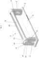
- FIGS. 1 to 3 show an embodiment of a connection system according to the invention.
- the connection system 1 comprises a bearing block 2 and a bearing block 3.
- the bearing blocks 2 and 3 are arranged on a base plate 4.
- the base plate 4 has fastening elements 5 in the form of spring hooks.
- the bearing block 2 has the opening 6, the bearing block 3 has the opening 7.
- the opening 7 is essentially circular. The same also applies to the opening 6, which, however, has an eccentric widening in the front area in the area 11.
- connection system comprises a connecting bolt 8, which has an extension of the bolt 10 in the area of its front end 9, resulting in an eccentricity.
- the widening of the bolt 10 runs in the widening of the opening 11.
- the widening of the opening is not continuous in the embodiment shown, but only on the surface.
- a stop/locking cam 12 is arranged on the back of the bearing block 2 .
- the spring bar 13 of the connecting bolt 8 runs on this, in which it runs along the run-up ramp 16 until it engages in the locking groove 17 .
- the figures show that the bolt cross section 18 is flattened.
- the spring bar 13 is designed so long that it forms a rear stop edge 19 with which the bolt runs against the bearing block 3 .
- the base plate 4 is designed in such a way that the heights of the bearing blocks are adapted to an intended installation position.
- the openings 6 and 7 are aligned and thus offer an introduction for the connecting bolt 8.
- the connecting bolt 8 is only in the in figure 1 position shown can be inserted at all into the bearing block 2 and can be carried out up to the bearing block 3, since the spring bar 13 runs in the groove 14 of the bearing block 2. Only in the figure 1 shown plug-in position, the connecting bolt 8 can be rotated. For this purpose, in a suitable tool, for example a screwdriver, can be inserted into the actuation slot 15 .
- connection system shows a possible use of the connection system according to the invention.
- two housings 20 and 21 are to be connected to one another.
- the surfaces in the connection area 22 lie on top of one another.
- the surfaces have suitable bushings 24 so that the bearing blocks protrude from a housing 21 through the bushings 24 into the interior of the housing 20 .
- the base plate 4 then rests against the inner surface of the housing 21 .
- the connecting bolt 8 is now pushed into the openings of the bearing blocks 2 and 3 which protrude into the housing 20 .
- the figures 5 and 6 show that the opening 6 is partially covered by the wall of the housing 20 in a lower bracing area 23 . If the connecting bolt 8 is now actuated, for example by inserting a screwdriver into the actuating slot 15 and turning it, the connecting bolt 8 reaches the in figure 6 position shown. Due to the eccentricity, the bolt in the connection area 23 now braces itself against the inner surface of the housing 20. This occurs over the entire length of the connection bolt, so that a very good connection of the two housings 20 and 21 is produced in the simplest possible way.
Landscapes
- Engineering & Computer Science (AREA)
- General Engineering & Computer Science (AREA)
- Mechanical Engineering (AREA)
- Microelectronics & Electronic Packaging (AREA)
- Connection Of Plates (AREA)
- Snaps, Bayonet Connections, Set Pins, And Snap Rings (AREA)
- Paper (AREA)
- Quick-Acting Or Multi-Walled Pipe Joints (AREA)
- Details Of Connecting Devices For Male And Female Coupling (AREA)
Priority Applications (1)
| Application Number | Priority Date | Filing Date | Title |
|---|---|---|---|
| EP22206110.3A EP4151865B1 (fr) | 2018-12-04 | 2018-12-04 | Système de connecteur |
Applications Claiming Priority (2)
| Application Number | Priority Date | Filing Date | Title |
|---|---|---|---|
| EP22206110.3A EP4151865B1 (fr) | 2018-12-04 | 2018-12-04 | Système de connecteur |
| EP18210173.3A EP3663592B1 (fr) | 2018-12-04 | 2018-12-04 | Système de raccordement |
Related Parent Applications (2)
| Application Number | Title | Priority Date | Filing Date |
|---|---|---|---|
| EP18210173.3A Division EP3663592B1 (fr) | 2018-12-04 | 2018-12-04 | Système de raccordement |
| EP18210173.3A Division-Into EP3663592B1 (fr) | 2018-12-04 | 2018-12-04 | Système de raccordement |
Publications (3)
| Publication Number | Publication Date |
|---|---|
| EP4151865A1 true EP4151865A1 (fr) | 2023-03-22 |
| EP4151865B1 EP4151865B1 (fr) | 2026-02-11 |
| EP4151865C0 EP4151865C0 (fr) | 2026-02-11 |
Family
ID=64606734
Family Applications (2)
| Application Number | Title | Priority Date | Filing Date |
|---|---|---|---|
| EP18210173.3A Active EP3663592B1 (fr) | 2018-12-04 | 2018-12-04 | Système de raccordement |
| EP22206110.3A Active EP4151865B1 (fr) | 2018-12-04 | 2018-12-04 | Système de connecteur |
Family Applications Before (1)
| Application Number | Title | Priority Date | Filing Date |
|---|---|---|---|
| EP18210173.3A Active EP3663592B1 (fr) | 2018-12-04 | 2018-12-04 | Système de raccordement |
Country Status (5)
| Country | Link |
|---|---|
| EP (2) | EP3663592B1 (fr) |
| DK (1) | DK3663592T3 (fr) |
| FI (1) | FI3663592T3 (fr) |
| HU (1) | HUE061565T2 (fr) |
| PL (1) | PL3663592T3 (fr) |
Citations (3)
| Publication number | Priority date | Publication date | Assignee | Title |
|---|---|---|---|---|
| EP0046223A1 (fr) * | 1980-08-20 | 1982-02-24 | Rudolf Schaefer | Dispositif de tension pour tubes |
| FR2540946A3 (fr) * | 1983-02-10 | 1984-08-17 | Heer & Co | Organe de fixation pour l'assemblage de dispositifs porteurs, en particulier de caniveaux pour cables |
| DE102012018694A1 (de) * | 2012-09-21 | 2014-03-27 | Pyramid Computer Gmbh | Baukasten mit zwei, an benachbarten Gehäuseseiten aneinander anliegenden Gehäusen |
-
2018
- 2018-12-04 FI FIEP18210173.3T patent/FI3663592T3/fi active
- 2018-12-04 DK DK18210173.3T patent/DK3663592T3/da active
- 2018-12-04 PL PL18210173.3T patent/PL3663592T3/pl unknown
- 2018-12-04 EP EP18210173.3A patent/EP3663592B1/fr active Active
- 2018-12-04 EP EP22206110.3A patent/EP4151865B1/fr active Active
- 2018-12-04 HU HUE18210173A patent/HUE061565T2/hu unknown
Patent Citations (3)
| Publication number | Priority date | Publication date | Assignee | Title |
|---|---|---|---|---|
| EP0046223A1 (fr) * | 1980-08-20 | 1982-02-24 | Rudolf Schaefer | Dispositif de tension pour tubes |
| FR2540946A3 (fr) * | 1983-02-10 | 1984-08-17 | Heer & Co | Organe de fixation pour l'assemblage de dispositifs porteurs, en particulier de caniveaux pour cables |
| DE102012018694A1 (de) * | 2012-09-21 | 2014-03-27 | Pyramid Computer Gmbh | Baukasten mit zwei, an benachbarten Gehäuseseiten aneinander anliegenden Gehäusen |
Also Published As
| Publication number | Publication date |
|---|---|
| DK3663592T3 (da) | 2023-04-24 |
| EP4151865B1 (fr) | 2026-02-11 |
| PL3663592T3 (pl) | 2023-08-07 |
| EP3663592B1 (fr) | 2023-01-25 |
| EP3663592A1 (fr) | 2020-06-10 |
| EP4151865C0 (fr) | 2026-02-11 |
| HUE061565T2 (hu) | 2023-07-28 |
| FI3663592T3 (fi) | 2023-04-20 |
Similar Documents
| Publication | Publication Date | Title |
|---|---|---|
| EP0136431B1 (fr) | Ossature en profilés | |
| EP3649353B1 (fr) | Système de fixation | |
| EP2685111A1 (fr) | Dispositif de serrage de connexion amovibles de deux pièces profilées | |
| DE2820218A1 (de) | Befestigungselement zur loesbaren verbindung von zwei plattenartigen bauteilen | |
| EP1995829B1 (fr) | Système de codage pour connecteurs à fiches subminiatures D | |
| EP3421691B1 (fr) | Cylindre de fermeture modulaire | |
| EP2420685B1 (fr) | Connecteur de raccordement de rainures profilées ainsi qu'agencement doté de ce type de connecteur | |
| DE102012208482A1 (de) | Befestigungsvorrichtung | |
| EP3557084B1 (fr) | Élément de raccordement permettant de raccorder des éléments profilés | |
| DE102008034775A1 (de) | Vorrichtung zum Verbinden zweier Schränke für Schaltgeräte | |
| EP0731282B1 (fr) | Elément de fixation | |
| EP3663592B1 (fr) | Système de raccordement | |
| AT408561B (de) | Schutzzaun | |
| EP3973818A1 (fr) | Paroi latérale de tiroir | |
| EP3663500B1 (fr) | Ferrure de verrouillage pour parties structurales de cadre adjacentes les unes aux autres | |
| EP4114150A1 (fr) | Ensemble d'extension | |
| DE69305423T2 (de) | Verkehrszeichen | |
| EP3828426A1 (fr) | Élément de fixation pour tubes à plusieurs bordures | |
| DE102014100757A1 (de) | Tür- und/oder Fensterbeschlag-Befestigungsvorrichtung | |
| WO2008151716A2 (fr) | Système de meuble et meuble | |
| DE102008008695A1 (de) | Profilverbinder | |
| EP3088815B1 (fr) | Sortie d'air | |
| DE20317863U1 (de) | Anordnung mit wenigstens zwei über ein Verbindungselement verbindbaren Bauteilen | |
| DE20015585U1 (de) | Verbindungsbeschlag | |
| DE20212811U1 (de) | Parallelverbinder |
Legal Events
| Date | Code | Title | Description |
|---|---|---|---|
| PUAI | Public reference made under article 153(3) epc to a published international application that has entered the european phase |
Free format text: ORIGINAL CODE: 0009012 |
|
| STAA | Information on the status of an ep patent application or granted ep patent |
Free format text: STATUS: THE APPLICATION HAS BEEN PUBLISHED |
|
| STAA | Information on the status of an ep patent application or granted ep patent |
Free format text: STATUS: REQUEST FOR EXAMINATION WAS MADE |
|
| AC | Divisional application: reference to earlier application |
Ref document number: 3663592 Country of ref document: EP Kind code of ref document: P |
|
| AK | Designated contracting states |
Kind code of ref document: A1 Designated state(s): AL AT BE BG CH CY CZ DE DK EE ES FI FR GB GR HR HU IE IS IT LI LT LU LV MC MK MT NL NO PL PT RO RS SE SI SK SM TR |
|
| 17P | Request for examination filed |
Effective date: 20230316 |
|
| RBV | Designated contracting states (corrected) |
Designated state(s): AL AT BE BG CH CY CZ DE DK EE ES FI FR GB GR HR HU IE IS IT LI LT LU LV MC MK MT NL NO PL PT RO RS SE SI SK SM TR |
|
| P01 | Opt-out of the competence of the unified patent court (upc) registered |
Effective date: 20230516 |
|
| STAA | Information on the status of an ep patent application or granted ep patent |
Free format text: STATUS: EXAMINATION IS IN PROGRESS |
|
| 17Q | First examination report despatched |
Effective date: 20240305 |
|
| RIC1 | Information provided on ipc code assigned before grant |
Ipc: F16B 5/06 20060101AFI20250730BHEP Ipc: H05K 5/00 20060101ALI20250730BHEP Ipc: F16B 21/02 20060101ALN20250730BHEP |
|
| GRAP | Despatch of communication of intention to grant a patent |
Free format text: ORIGINAL CODE: EPIDOSNIGR1 |
|
| STAA | Information on the status of an ep patent application or granted ep patent |
Free format text: STATUS: GRANT OF PATENT IS INTENDED |
|
| INTG | Intention to grant announced |
Effective date: 20250905 |
|
| GRAS | Grant fee paid |
Free format text: ORIGINAL CODE: EPIDOSNIGR3 |
|
| GRAA | (expected) grant |
Free format text: ORIGINAL CODE: 0009210 |
|
| STAA | Information on the status of an ep patent application or granted ep patent |
Free format text: STATUS: THE PATENT HAS BEEN GRANTED |
|
| AC | Divisional application: reference to earlier application |
Ref document number: 3663592 Country of ref document: EP Kind code of ref document: P |
|
| AK | Designated contracting states |
Kind code of ref document: B1 Designated state(s): AL AT BE BG CH CY CZ DE DK EE ES FI FR GB GR HR HU IE IS IT LI LT LU LV MC MK MT NL NO PL PT RO RS SE SI SK SM TR |
|
| REG | Reference to a national code |
Ref country code: CH Ref legal event code: F10 Free format text: ST27 STATUS EVENT CODE: U-0-0-F10-F00 (AS PROVIDED BY THE NATIONAL OFFICE) Effective date: 20260211 Ref country code: GB Ref legal event code: FG4D Free format text: NOT ENGLISH |
|
| REG | Reference to a national code |
Ref country code: DE Ref legal event code: R096 Ref document number: 502018016385 Country of ref document: DE |
|
| REG | Reference to a national code |
Ref country code: IE Ref legal event code: FG4D Free format text: LANGUAGE OF EP DOCUMENT: GERMAN |
|
| U01 | Request for unitary effect filed |
Effective date: 20260218 |
|
| P04 | Withdrawal of opt-out of the competence of the unified patent court (upc) registered |
Free format text: CASE NUMBER: UPC_APP_164099_1/2023 Effective date: 20260225 |
|
| U07 | Unitary effect registered |
Designated state(s): AT BE BG DE DK EE FI FR IT LT LU LV MT NL PT RO SE SI Effective date: 20260225 |