EP2685111A1 - Dispositif de serrage de connexion amovibles de deux pièces profilées - Google Patents
Dispositif de serrage de connexion amovibles de deux pièces profilées Download PDFInfo
- Publication number
- EP2685111A1 EP2685111A1 EP12176195.1A EP12176195A EP2685111A1 EP 2685111 A1 EP2685111 A1 EP 2685111A1 EP 12176195 A EP12176195 A EP 12176195A EP 2685111 A1 EP2685111 A1 EP 2685111A1
- Authority
- EP
- European Patent Office
- Prior art keywords
- clamping device
- plate
- profile
- profile piece
- hook
- Prior art date
- Legal status (The legal status is an assumption and is not a legal conclusion. Google has not performed a legal analysis and makes no representation as to the accuracy of the status listed.)
- Granted
Links
Images



Classifications
-
- F—MECHANICAL ENGINEERING; LIGHTING; HEATING; WEAPONS; BLASTING
- F16—ENGINEERING ELEMENTS AND UNITS; GENERAL MEASURES FOR PRODUCING AND MAINTAINING EFFECTIVE FUNCTIONING OF MACHINES OR INSTALLATIONS; THERMAL INSULATION IN GENERAL
- F16B—DEVICES FOR FASTENING OR SECURING CONSTRUCTIONAL ELEMENTS OR MACHINE PARTS TOGETHER, e.g. NAILS, BOLTS, CIRCLIPS, CLAMPS, CLIPS OR WEDGES; JOINTS OR JOINTING
- F16B12/00—Jointing of furniture or the like, e.g. hidden from exterior
- F16B12/10—Jointing of furniture or the like, e.g. hidden from exterior using pegs, bolts, tenons, clamps, clips, or the like
-
- F—MECHANICAL ENGINEERING; LIGHTING; HEATING; WEAPONS; BLASTING
- F16—ENGINEERING ELEMENTS AND UNITS; GENERAL MEASURES FOR PRODUCING AND MAINTAINING EFFECTIVE FUNCTIONING OF MACHINES OR INSTALLATIONS; THERMAL INSULATION IN GENERAL
- F16B—DEVICES FOR FASTENING OR SECURING CONSTRUCTIONAL ELEMENTS OR MACHINE PARTS TOGETHER, e.g. NAILS, BOLTS, CIRCLIPS, CLAMPS, CLIPS OR WEDGES; JOINTS OR JOINTING
- F16B7/00—Connections of rods or tubes, e.g. of non-circular section, mutually, including resilient connections
- F16B7/04—Clamping or clipping connections
- F16B7/044—Clamping or clipping connections for rods or tubes being in angled relationship
- F16B7/0446—Clamping or clipping connections for rods or tubes being in angled relationship for tubes using the innerside thereof
-
- F—MECHANICAL ENGINEERING; LIGHTING; HEATING; WEAPONS; BLASTING
- F16—ENGINEERING ELEMENTS AND UNITS; GENERAL MEASURES FOR PRODUCING AND MAINTAINING EFFECTIVE FUNCTIONING OF MACHINES OR INSTALLATIONS; THERMAL INSULATION IN GENERAL
- F16B—DEVICES FOR FASTENING OR SECURING CONSTRUCTIONAL ELEMENTS OR MACHINE PARTS TOGETHER, e.g. NAILS, BOLTS, CIRCLIPS, CLAMPS, CLIPS OR WEDGES; JOINTS OR JOINTING
- F16B7/00—Connections of rods or tubes, e.g. of non-circular section, mutually, including resilient connections
- F16B7/04—Clamping or clipping connections
-
- F—MECHANICAL ENGINEERING; LIGHTING; HEATING; WEAPONS; BLASTING
- F16—ENGINEERING ELEMENTS AND UNITS; GENERAL MEASURES FOR PRODUCING AND MAINTAINING EFFECTIVE FUNCTIONING OF MACHINES OR INSTALLATIONS; THERMAL INSULATION IN GENERAL
- F16B—DEVICES FOR FASTENING OR SECURING CONSTRUCTIONAL ELEMENTS OR MACHINE PARTS TOGETHER, e.g. NAILS, BOLTS, CIRCLIPS, CLAMPS, CLIPS OR WEDGES; JOINTS OR JOINTING
- F16B7/00—Connections of rods or tubes, e.g. of non-circular section, mutually, including resilient connections
- F16B7/04—Clamping or clipping connections
- F16B7/044—Clamping or clipping connections for rods or tubes being in angled relationship
- F16B7/0446—Clamping or clipping connections for rods or tubes being in angled relationship for tubes using the innerside thereof
- F16B7/0473—Clamping or clipping connections for rods or tubes being in angled relationship for tubes using the innerside thereof with hook-like parts gripping, e.g. by expanding, behind the flanges of a profile
Definitions
- the present invention relates to a clamping device for releasably connecting two profile pieces, in particular a first with a second profile piece, wherein the clamping device is inserted into a recess provided in the first profile piece, with at least one hook element for engaging in the first profile piece and with a Verspannnelement, with in which the at least one hook element can be brought into at least one complementary locking element of the first profile piece in the releasable engagement.
- a clamping device of the above type is for example from the WO 99/09326 the applicant known.
- the known clamping device comprises a closure sleeve inserted into a first profile piece, which can be locked with corresponding elements in the second profile piece.
- Such clamping devices are intended to connect two profile pieces together. It is in the one profile piece usually a profiled rod to which a wall profile is attached.
- the wall profile can also be a cross strut and usually has a greater transverse extent than a profiled bar mostly aligned along the longitudinal axis.
- an internal cutout is laterally provided for each clamping device, in which the clamping device can be inserted up to the protruding hook elements.
- Such a clamping device is also from the WO 97/25536 known, where on one side of the wall surface, a round bore is provided, through which the locking head extends therethrough, after being sunk against the action of a spring force in the clamping device through the cutout to the bore. in which he locks.
- this VorInstituthülse is thus advanced in a cutout of the wall plate and a control knob protrudes at least on one side of the wall plate from this - in particular flush - out.
- the said control knob also absorbs tensile forces acting on the wall plate and trying to separate them from the profile strip.
- a clamping device for releasably connecting a first with a second profile piece, wherein the clamping device is insertable into a recess provided in the first profile piece and is provided with at least one hook element for engaging in the first profile piece and with a Verspannnelement.
- the clamping device comprises for this purpose a plate, wherein the at least one hook element is aligned in the plane of the plate on the first profile piece, and the clamping element is provided on the opposite side of the plate relative to the hook member to clamp the plate against the second profile piece.
- the bracing member may then comprise a screw connected to the plate or a bolt, which or which projects into a space provided behind the plate cavity to be clamped with securing elements against the second profile piece.
- the bracing element may be a screw and then the securing element is for example a nut. Then, in particular, a retaining clip can be arranged under the screw, which engage with longitudinal grooves in the two receiving the plate receiving cavity side walls, to transmit the force over a larger area on the rather thin wall elements against rotation.
- the bracing element can also be a bolt, in which case the securing element comprises a lever lock, that is to say a pivotable lever with which a closing force is transmitted to the bolt via a discharge curve, advantageously over a dead center.
- the securing element comprises a lever lock, that is to say a pivotable lever with which a closing force is transmitted to the bolt via a discharge curve, advantageously over a dead center.
- the locking elements may be bolts which project transversely through the recess to be gripped by the hook element (s) during assembly and to be tightened against the plate for locking by the clamping element.
- these may have a transverse bore for receiving a Sich ceremoniesssplints when the other end has a flange.
- the bolts are provided in transverse holes.
- the wall behind the recess in the region of the bolts can be broken in order to allow the bolts to engage behind the slide plate.
- the breakthrough of the wall behind the recess for example, a slot.
- the lower edge of the opening of the wall behind the recess can be used as an abutment for the Lower edge of the slide plate) serve.
- the plate can be clamped with its upper side in leading and load-bearing contact in the second profile piece and the underside of the plate can be supported load-bearing on a surface of the first profile piece.
- the underside of the hook recess (s) can be supported on the load-bearingly connected to the plate element (s).
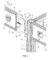
- the Fig. 1 shows a perspective view of an insert of an embodiment of a clamping device according to the invention on a vertical profile post 10.
- the profile post 10 is a first profile piece, which post is usually placed vertically. It is for example an aluminum profile with an inner cavity 13 and with at least on each of its four sides a central groove 11 as a fastening groove.
- it is a post 10 with still two laterally further provided grooves 12 on both sides of the central groove 11.
- wall elements in these grooves 11, 12 and 13 are fixed and held by transversely engaging in the undercuts of the grooves closures.
- the goal is a second transverse oriented To attach profile piece 20 to the first profile piece 10, which can derive on the top 90 acting loads on the post 10.
- two second profile pieces 20 are already attached as cross struts on the right side of the picture.
- the attachment can be seen in particular because, as will be apparent from the further description that a nut 50 is placed on a locking screw 31 and thereby presses a retaining clip 40 on an inner wall of this cross member 20.
- Fig. 1 In an exploded view of the Fig. 1 is another second profile piece 20 shown on the left side of the image before it is attached to the profile post 10.
- the second profile piece 20 has an upper rail 22 with three mounting grooves 24, which are aligned upwards and to the two sides and advantageously but not necessarily have undercuts. At the bottom of a lower rail 23 is also provided with three cultivation grooves. In between, there extends a connecting wall which is hollow at least in this end region of the transverse strut 20 and which comprises two side walls 27 between which there is a receiving cavity 21.
- the receiving cavity 21 terminates in the region of the upper or lower profile rail 22 and 23 in a stepped guide groove 26 in which the slide plate 30 is guided.
- the slide plate 30 is a generally rectangular element with flat opposite side walls, in the rear in the middle of a locking screw 31 is fixed, which is integrally connected via the connecting element 39 with the slide plate. It may be simply a metal plate 30, which has a recess in the region of the connecting element 39, in which a flattened end without thread of the locking screw 31 is inserted.
- the dimensions of the receiving cavity 21 and the slide plate 30 are such that the upper edge 34 and the lower edge 36 respectively in the opposite guide grooves 26 fit and when pushing the slide plate into the recess 21, the locking screw 31 protrudes into the locking recess 25 while on the other side, the two hooks 32 and 33 over the edges of the front walls 27 of the second profile piece 20th protrude.
- the locking screw 31 passes through a retaining clip 40 in its central opening 42 and is locked by a nut 50.
- the two hooks 32 and 33 project beyond a front abutment edge 49.
- the upper side surface 34 is offset by a stepped step 35 down.
- the Fig. 2 shows a perspective view of an insert of an embodiment of a clamping device on another embodiment of a profile piece.
- various first profile pieces 10, 110 are called or described as extension profile 210; and also different cross struts 20, 120, 220, 320 as Anschraubprofil in any combination possible.
- Each similar features are denoted by similar reference numerals.
- the second profile piece 120 has an upper and lower profile rail 122 or 123, which has three mounting grooves to the top or bottom and thus comprises a structure such as the post 10 with three grooves.
- mounting grooves 124 which are also aligned in the opposite direction. Otherwise, the two side walls 127 which form with the guide grooves 26, the cavity for receiving the slightly modified slide plate member 130, the same design.
- the locking screw 31 passes through the passage opening 42 of the retaining clip 40, which have two alignment grooves 41 extending transversely thereto.
- the alignment grooves 41 are intended to engage the side walls 129 of the recess and thus prevent twisting of this element 40.
- the Retaining clip 40 is also provided with a recessed step 128 depression in the side walls 129, so that when tightening the nut 50 on the screw 31, the retaining clip 40 fits into the step 128 and in this end position, the screw 31 and thus attracts the hook 32nd and 33 moves in their direction.
- the front surface of the support post 10 is brought into contact with the front side wall 29 of the profile piece 20.
- This wall 29 is formed both by areas of the two side walls 27 and the front ends of the upper and lower profiles 22 and 23.
- the slide plate 130 has as the slide plate 30 from the Fig. 1 an upper edge 34 and a lower edge 36, in which case the hooks 32 and 33 are arranged within the front edge or contact edge 149 of the slide plate 130.
- the hook cavities 137 form L-shaped recesses, for safe hooking here additionally the hooks 32 and 33 are provided with corresponding projecting hook nose 38, which supports a different attachment to a support post 10, as follows with a description of Fig. 5 and 6 will be provided.
- the Fig. 3 shows a perspective view of an insert of an embodiment of a clamping device with another embodiment of a Verspannements.
- the tensioning element in the Fig. 1 and 2 was a retaining clip 40 with vertical grooves 41 for oriented support on the side walls 27 of the second profile piece 20.
- this bracing element may also be simply a washer 140 through which the screw 31 is guided along the screw axis 51.
- the side wall 20 here corresponds to the cross member of the Fig. 1 with only one groove 24 having top 90th
- the Fig. 4 shows a perspective view of an insert of an embodiment of a clamping device with a crossbar 220 as a second profile piece with a coupling element 320 for another second profile piece 120 in this figure.
- the coupling element is the second attachment profile 320, which pass through four fixing screws 328, which are guided through openings in the solticiansflanschen 329 of Aufschraubprofils 320 through corresponding attachment holes 327 in the cross brace 220, then on the other side of the local wall over a nut 325 and washer 326 combination to be securely fastened.
- a second transverse strut 220 which may also be the struts 120 or 20, to arrange an intermediate profile between the posts to the patch on the top 92 load on the cross strut 220 here on a support post 10 (in the figure not shown).
- the Aufschraubprofil 320 has a vertically oriented receiving cavity 321, in which an undercut groove is provided in the front region. As with the receiving cavity 11, it is not necessarily necessary that this groove is undercut.
- Fig. 1 is provided in the depth of the receiving cavity 11 a longitudinally aligned along the post combination of slots for the passage of the lugs 32, 33;
- bolt holes 345 are provided transversely to this receiving cavity into which, as will be described later, bolts 146 are performed, which will then engage in the hook cavities 37 of the slide plate.
- the attachment and fixation in the horizontal direction also happens here again on the combination of retaining clip 40 and nut 50.
- the front side wall 29 of the second profile piece 120 in this situation is drawn onto the surfaces 29 of the mounting profile piece 320 and the cross brace 220 and locked horizontally ,
- the Fig. 5 shows a support head 110, which is used in conjunction with the post 10.
- This support head 110 is essentially an adapter piece, which, like the attachment profile piece 320, is provided exactly for the purpose of fastening the transverse struts 20, 120, etc.
- the support head 110 has a top 113 and a corresponding opposite bottom, both of which are planar and in each of which in the longitudinal direction of the support head 110 in the corners through holes 114 are provided for attachment to the corresponding continuing profiles. These corners have a flat corner surface 119
- the insertion groove 111 is milled out in the molding material and undercut in the central region, as can be seen from the bent gate region at the ends of the groove of the figure.
- Eckaus traditions 112 have a substantial length between the bottom portion 116 and cover portion 115 of the support head 110.
- two bolt holes 145 are provided by each wall 117 of the grooves 111, through which a bolt 146 is inserted.
- This bolt 146 then forms the possibility for the slide plate 30, 130 to reach over and hook into it.
- the front wall 118 is then pulled in horizontally frictional contact with the opposite front wall 29 of the cross member 20, brought and held.
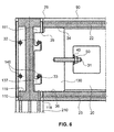
- the Fig. 6 now shows in a sectional view through such a support head 110, the lateral attachment of a slide plate 130.
- the stub head 110 rests on an extension profile 210 and is for example by (not shown) screws and bolts through the openings 114 connected thereto.
- the upper step portion 35 is necessary to use the necessary clearance in the insertion groove 111 so that the upper hook 32 can grip over the bolt 146.
- the upper surface 34 of the slide plate 30 rests against the underside of the insertion groove 26 and thus absorbs the weight which rests on the element, for example on the upper side 90. This gives (in the Fig. 6 ) at an oblique angle from top right to bottom left the load on the lower side edge 36 on and on the area which is supported on the underside of the insertion 111 on the corner surfaces 119.
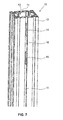
- the Fig. 7 shows a perspective view of the vertical profile post 10 from Fig. 1 , In the middle groove 11, the two slots 14 and 16 can be seen between which the full area of the bottom 16 of the groove 11 can be seen.
- the slots 14 and 16 have a length such that they can receive the hooks 32 and 33.
- the height of the upper slot 14 is such that the second profile 20 is flush with the top 91 when the slide 30 is inserted. For example, this may be a distance of 2.5 centimeters; wherein the two hooks 32 and 33 protrude into slots 14 and 15 with a length of 5 centimeters, between which there is a distance of 6 centimeters.
- the two slots 14 and 15 may also be located farther away from the upper edge. When inserting the slider 30 protrudes its front edge 49 of the groove bottom 16 and thus abuts against this. It would also be possible to use an insert not shown in the drawings in a third slot on which then the front portion of the bottom 36 could be discontinued.
- Fig. 8 shows a perspective view of an insert of an embodiment of a clamping device according to the invention on a variant of a vertical profile post 310th Die
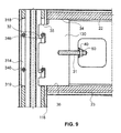
- Fig. 9 shows a partially sectioned view of the profile 210 to Fig. 8 with attached cross-section 20 with clamping device according to an embodiment of the invention.
- the use of the same and similar reference numbers shows that the individual features of a post 310 can be connected to suitable transverse profiles 130.
- a single front undercut groove 111 is provided, which is closed with a rear wall 311 to a cavity in the profile 310.
- the Applicant has found that it is statically advantageous not to provide the load without support of the lower edge 36 on a corresponding impact, but as in the Fig. 8 and 9 shown to provide this lower edge 36 on the bottom 319 of a receiving slot 314.
- the upper portion of the slide plate 30 can be inserted between the upper edge 318 and the upper pin 346, and then with the nose to include the hook 32.
- the bolt 346 can be inserted in a captive interference fit in the corresponding transverse holes in the wall of the profile 310.
- the load then rests on the one hand through-side walls with the only scratched side grooves 312 as well as on the lower edge 319 of the slot 314.
- a slot 314 is provided at the appropriate intervals along the profile 310.
- the slide plate 130 is retracted horizontally by tightening the nut as in the other embodiments, until the leading edge 118 touches the front edge of the profile 310 and is braced there.
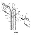
- the Fig. 10 shows a perspective view of an insert of an embodiment of a clamping device according to the invention to another variant of the attachment of a vertical profile post 310.
- no bolts 346 are pressed, but these include a flange formed as a bolt head 347 and on the opposite Page a snap ring 348, or if necessary a sapwood.
- the bolts 346 are releasably secured according to this embodiment against falling out, while according to the embodiment of the Fig. 8 and 9 are provided in a press fit as a safeguard against losing.
- two bolts are provided in each case; it could also be three or four bolts with corresponding, more lugs 32, 33 having slide plates 130.
Landscapes
- Engineering & Computer Science (AREA)
- General Engineering & Computer Science (AREA)
- Mechanical Engineering (AREA)
- Connection Of Plates (AREA)
- Mutual Connection Of Rods And Tubes (AREA)
- Clamps And Clips (AREA)
- Joining Of Building Structures In Genera (AREA)
Priority Applications (10)
| Application Number | Priority Date | Filing Date | Title |
|---|---|---|---|
| EP12176195.1A EP2685111B1 (fr) | 2012-07-09 | 2012-07-12 | Dispositif de serrage de connexion amovibles de deux pièces profilées |
| PL12176195T PL2685111T3 (pl) | 2012-07-09 | 2012-07-12 | Mocowanie zaciskowe do rozłącznego łączenia dwóch profili |
| AU2013206115A AU2013206115B2 (en) | 2012-07-09 | 2013-05-31 | Clamping device for the releasable connection of two profile sections |
| US13/920,413 US9476441B2 (en) | 2012-07-09 | 2013-06-18 | Clamping device for the releasable connection of two profile sections |
| CN201310256518.7A CN103541968B (zh) | 2012-07-09 | 2013-06-25 | 用于两个型材部可拆卸连接的夹持装置 |
| KR1020130075285A KR102047771B1 (ko) | 2012-07-09 | 2013-06-28 | 두 프로파일부의 해제가능한 연결을 위한 클램핑 장치 |
| JP2013137776A JP6366163B2 (ja) | 2012-07-09 | 2013-07-01 | 2つのプロファイル部分を取り外し可能に接続するためのクランプ装置 |
| EA201370132A EA029670B1 (ru) | 2012-07-09 | 2013-07-02 | Система для разъемного соединения двух профилированных секций |
| MX2013007772A MX341899B (es) | 2012-07-09 | 2013-07-03 | Dispositivo de sujecion para la conexion liberable de dos secciones de perfil. |
| HRP20191318TT HRP20191318T1 (hr) | 2012-07-09 | 2019-07-22 | Spojni uređaj za razdvojivo povezivanje dva profilna elementa |
Applications Claiming Priority (2)
| Application Number | Priority Date | Filing Date | Title |
|---|---|---|---|
| EP12175588 | 2012-07-09 | ||
| EP12176195.1A EP2685111B1 (fr) | 2012-07-09 | 2012-07-12 | Dispositif de serrage de connexion amovibles de deux pièces profilées |
Publications (2)
| Publication Number | Publication Date |
|---|---|
| EP2685111A1 true EP2685111A1 (fr) | 2014-01-15 |
| EP2685111B1 EP2685111B1 (fr) | 2019-05-01 |
Family
ID=46545257
Family Applications (1)
| Application Number | Title | Priority Date | Filing Date |
|---|---|---|---|
| EP12176195.1A Active EP2685111B1 (fr) | 2012-07-09 | 2012-07-12 | Dispositif de serrage de connexion amovibles de deux pièces profilées |
Country Status (12)
| Country | Link |
|---|---|
| US (1) | US9476441B2 (fr) |
| EP (1) | EP2685111B1 (fr) |
| JP (1) | JP6366163B2 (fr) |
| KR (1) | KR102047771B1 (fr) |
| CN (1) | CN103541968B (fr) |
| AU (1) | AU2013206115B2 (fr) |
| EA (1) | EA029670B1 (fr) |
| ES (1) | ES2731439T3 (fr) |
| HR (1) | HRP20191318T1 (fr) |
| MX (1) | MX341899B (fr) |
| PL (1) | PL2685111T3 (fr) |
| TR (1) | TR201910441T4 (fr) |
Cited By (1)
| Publication number | Priority date | Publication date | Assignee | Title |
|---|---|---|---|---|
| EP3669032A1 (fr) * | 2017-08-18 | 2020-06-24 | Knauf Gips KG | Ossature, charpente, profilé et ensemble d'éléments structuraux pour construction modulaire et bâtiment de construction modulaire |
Families Citing this family (21)
| Publication number | Priority date | Publication date | Assignee | Title |
|---|---|---|---|---|
| US8689511B2 (en) | 2009-08-31 | 2014-04-08 | Joseph C. Fleming, III | Method and system for interconnecting structural panels |
| US10501929B2 (en) * | 2013-09-30 | 2019-12-10 | Drew P. HENRY | Hollow connector sleeve with interlocking components |
| CN104924959A (zh) * | 2015-05-20 | 2015-09-23 | 成都科创佳思科技有限公司 | 一种自卸汽车后挡板的紧固结构 |
| CN106369019B (zh) | 2015-07-20 | 2020-07-14 | 锁栓公司 | 夹锁紧固件和紧固系统 |
| CN106369028B (zh) * | 2015-07-20 | 2021-06-04 | 锁栓公司 | 通道锁紧固件及紧固系统 |
| CN105240361B (zh) * | 2015-10-29 | 2018-07-31 | 天津星星模界科技有限公司 | 一种模块化家具的通用标准件 |
| US10975898B2 (en) * | 2016-11-14 | 2021-04-13 | Joseph C. Fleming, III | Method and system for interconnecting structural panels |
| WO2019083632A1 (fr) | 2017-10-27 | 2019-05-02 | Elfa International Ab | Système de stockage mural configurable |
| DE102017125877B4 (de) * | 2017-11-06 | 2019-06-19 | Festool Gmbh | Verankerungsbeschlag zur Verankerung in einem Werkstück |
| US11375812B2 (en) | 2018-09-12 | 2022-07-05 | Elfa International Ab | Wall-mounted, configurable storage system |
| JP7382136B2 (ja) * | 2018-12-21 | 2023-11-16 | 株式会社イトーキ | ねじ取付部材支持構造 |
| CN109812475A (zh) * | 2019-02-22 | 2019-05-28 | 滁州市超顺装备科技有限公司 | 一种方便连接的钣金件 |
| CN109798289A (zh) * | 2019-03-12 | 2019-05-24 | 江苏能建机电实业集团有限公司 | 一种铝型材组合体及其组装方法 |
| KR102150861B1 (ko) * | 2019-05-13 | 2020-09-04 | (주)아모스아인스가구 | 레버 가압식 조립구조를 갖는 확장형 인테리어 선반 |
| US12203267B2 (en) | 2019-12-23 | 2025-01-21 | Steelcase Inc. | Furniture system |
| SE543835C2 (en) | 2019-12-23 | 2021-08-10 | Elfa Int Ab | Shelf storage system comprising hang standards with screw holes at distances corresponding to desired bracket to bracket distances |
| SE544174C2 (en) | 2020-04-30 | 2022-02-22 | Elfa Int Ab | Hang standard and storage system including the hang standard |
| EP4649863A3 (fr) | 2020-04-30 | 2026-01-21 | Elfa International AB | Système de suspension comprenant un rail arrière agencé avec des brides s'étendant au moins partiellement dans différentes directions et un hangare agencement à cet effet |
| CA3228974A1 (fr) * | 2021-08-11 | 2023-02-16 | Cpg International Llc | Conception de structure externe et elements |
| CN217001180U (zh) * | 2021-08-11 | 2022-07-19 | 浙江永强集团股份有限公司 | 一种帐篷用梁柱快速组装结构 |
| KR102654127B1 (ko) * | 2023-04-21 | 2024-04-02 | 김병찬 | 알루미늄 프로파일 사출접합방법 |
Citations (4)
| Publication number | Priority date | Publication date | Assignee | Title |
|---|---|---|---|---|
| WO1997025536A1 (fr) | 1996-01-09 | 1997-07-17 | Syma Intercontinental Ag | Dispositif de serrage pour assemblage separable de deux pieces profilees |
| WO1999009326A1 (fr) | 1997-08-12 | 1999-02-25 | Syma Intercontinental Ag | Douille de fermeture pour un dispositif de serrage utilise pour assembler de facon liberable deux pieces profilees |
| DE29801042U1 (de) * | 1998-01-22 | 1999-06-17 | Krüger, Günther, 24248 Mönkeberg | Anordnung zum Verbinden des Endes eines mit mindestens einem Haken versehenen Hohlprofils mit einer quer dazu verlaufenden Tragplatte |
| WO2010057324A1 (fr) * | 2008-11-21 | 2010-05-27 | Syma Intercontinental Ag | Dispositif pour l'assemblage de deux pièces profilées |
Family Cites Families (26)
| Publication number | Priority date | Publication date | Assignee | Title |
|---|---|---|---|---|
| US1974050A (en) * | 1931-07-21 | 1934-09-18 | Keil Francis & Son Inc | Shelf bracket construction |
| US3559357A (en) * | 1969-07-09 | 1971-02-02 | David A Lowe | Modular building system |
| AT300250B (de) * | 1969-09-25 | 1972-07-25 | Huelsta Werke Huels O H G | Beschlag zur Verbindung einer Möbelwand od.dgl. mit einer U-Profil-Schiene |
| CH531624A (de) * | 1970-08-19 | 1972-12-15 | Syma Intercontinental Sa | Baukonstruktion |
| JPS5111531Y2 (fr) * | 1972-07-08 | 1976-03-29 | ||
| SE379087B (fr) * | 1973-07-27 | 1975-09-22 | A G Offenbroich | |
| US4124317A (en) * | 1976-09-20 | 1978-11-07 | Metalworks Limited | Coupling means |
| SU599178A1 (ru) * | 1976-12-13 | 1978-03-25 | Московский Технологический Институт Легкой Промышленности | Способ определени дефектности изделий |
| US4133433A (en) * | 1977-03-28 | 1979-01-09 | Wolf Morris A | Merchandising display system |
| JPS5636341Y2 (fr) * | 1977-04-22 | 1981-08-27 | ||
| JPS58156807U (ja) * | 1982-04-16 | 1983-10-19 | オクタノルム・ヘルトリ−ブス・ゲ−エムベ−ハ− | 接続具 |
| US4607754A (en) * | 1983-05-19 | 1986-08-26 | Wolf Morris A | Merchandising display system and method |
| US4712286A (en) * | 1983-05-19 | 1987-12-15 | Wolf Morris A | Method for making merchandising display members |
| US4615503A (en) * | 1985-05-02 | 1986-10-07 | Clamp Swing Pricing Co. | Deli pegbar apparatus |
| US4700916A (en) * | 1986-06-05 | 1987-10-20 | Hamilton Industries, Inc. | Cantilever arm assembly for modular furniture |
| US5188326A (en) * | 1991-01-04 | 1993-02-23 | Colony, Incorporated | Adjustable adapter bracket |
| ATE150848T1 (de) | 1992-11-21 | 1997-04-15 | Hestex Systems Bv | Verbindungselement |
| US5403083A (en) * | 1993-03-01 | 1995-04-04 | Whirlpool Corporation | Laterally adjustable cantilever shelf for a refrigerator |
| US5499667A (en) * | 1994-06-21 | 1996-03-19 | Nakanishi Construction Company | Drill/cutting bit, and method of making structural joint |
| DE4328832C2 (de) | 1993-08-27 | 1995-11-23 | F & T Form & Technik | Aus Profilteilen bestehendes Gestell |
| US5636934A (en) * | 1994-06-21 | 1997-06-10 | Kyoto Mokuzou Kenchiku Kenkyuusho | Structural connector, and method of making structural joint |
| US6202965B1 (en) * | 1998-12-21 | 2001-03-20 | The Marvel Group, Inc. | Panel fastening system for modular office furniture |
| JP3418356B2 (ja) * | 1999-05-27 | 2003-06-23 | シモンズ株式会社 | ベッド用連結具 |
| US20050055969A1 (en) * | 2002-03-18 | 2005-03-17 | Simmons Robert J. | Building frame structure |
| US6966267B2 (en) * | 2003-01-31 | 2005-11-22 | Gemtron Corporation | Refrigerator compartment housing vertically adjustable shelves |
| US20070294953A1 (en) * | 2006-06-26 | 2007-12-27 | Ruby Guillen | Cubicle work space organizer |
-
2012
- 2012-07-12 PL PL12176195T patent/PL2685111T3/pl unknown
- 2012-07-12 ES ES12176195T patent/ES2731439T3/es active Active
- 2012-07-12 TR TR2019/10441T patent/TR201910441T4/tr unknown
- 2012-07-12 EP EP12176195.1A patent/EP2685111B1/fr active Active
-
2013
- 2013-05-31 AU AU2013206115A patent/AU2013206115B2/en active Active
- 2013-06-18 US US13/920,413 patent/US9476441B2/en active Active
- 2013-06-25 CN CN201310256518.7A patent/CN103541968B/zh active Active
- 2013-06-28 KR KR1020130075285A patent/KR102047771B1/ko active Active
- 2013-07-01 JP JP2013137776A patent/JP6366163B2/ja active Active
- 2013-07-02 EA EA201370132A patent/EA029670B1/ru not_active IP Right Cessation
- 2013-07-03 MX MX2013007772A patent/MX341899B/es active IP Right Grant
-
2019
- 2019-07-22 HR HRP20191318TT patent/HRP20191318T1/hr unknown
Patent Citations (4)
| Publication number | Priority date | Publication date | Assignee | Title |
|---|---|---|---|---|
| WO1997025536A1 (fr) | 1996-01-09 | 1997-07-17 | Syma Intercontinental Ag | Dispositif de serrage pour assemblage separable de deux pieces profilees |
| WO1999009326A1 (fr) | 1997-08-12 | 1999-02-25 | Syma Intercontinental Ag | Douille de fermeture pour un dispositif de serrage utilise pour assembler de facon liberable deux pieces profilees |
| DE29801042U1 (de) * | 1998-01-22 | 1999-06-17 | Krüger, Günther, 24248 Mönkeberg | Anordnung zum Verbinden des Endes eines mit mindestens einem Haken versehenen Hohlprofils mit einer quer dazu verlaufenden Tragplatte |
| WO2010057324A1 (fr) * | 2008-11-21 | 2010-05-27 | Syma Intercontinental Ag | Dispositif pour l'assemblage de deux pièces profilées |
Cited By (4)
| Publication number | Priority date | Publication date | Assignee | Title |
|---|---|---|---|---|
| EP3669032A1 (fr) * | 2017-08-18 | 2020-06-24 | Knauf Gips KG | Ossature, charpente, profilé et ensemble d'éléments structuraux pour construction modulaire et bâtiment de construction modulaire |
| CN114607050A (zh) * | 2017-08-18 | 2022-06-10 | 可耐福石膏两合公司 | 框、基本框架、模块、型材、用于模块化建造的结构元件组及模块化建筑 |
| AU2017428251B2 (en) * | 2017-08-18 | 2024-09-19 | Knauf Gips Kg | Frame, basic framework, module, profile and set of structural elements for modular construction and a modular-construction building |
| US12297638B2 (en) | 2017-08-18 | 2025-05-13 | Knauf Gips Kg | Frame, basic framework, module, profile and set of structural elements for modular construction and a modular-construction building |
Also Published As
| Publication number | Publication date |
|---|---|
| US20140010587A1 (en) | 2014-01-09 |
| AU2013206115A1 (en) | 2014-01-23 |
| KR20140007267A (ko) | 2014-01-17 |
| EA029670B1 (ru) | 2018-04-30 |
| ES2731439T3 (es) | 2019-11-15 |
| PL2685111T3 (pl) | 2020-03-31 |
| HRP20191318T1 (hr) | 2019-10-18 |
| MX341899B (es) | 2016-09-07 |
| EA201370132A3 (ru) | 2014-04-30 |
| US9476441B2 (en) | 2016-10-25 |
| JP2014016028A (ja) | 2014-01-30 |
| JP6366163B2 (ja) | 2018-08-01 |
| EP2685111B1 (fr) | 2019-05-01 |
| KR102047771B1 (ko) | 2019-12-04 |
| AU2013206115B2 (en) | 2016-12-01 |
| MX2013007772A (es) | 2014-01-17 |
| EA201370132A2 (ru) | 2014-01-30 |
| CN103541968A (zh) | 2014-01-29 |
| CN103541968B (zh) | 2017-03-01 |
| TR201910441T4 (tr) | 2019-08-21 |
Similar Documents
| Publication | Publication Date | Title |
|---|---|---|
| EP2685111B1 (fr) | Dispositif de serrage de connexion amovibles de deux pièces profilées | |
| AT404219B (de) | Schublade | |
| EP1987213B1 (fr) | Systeme de coffrage de plafond | |
| DE2704398C3 (de) | Aus Ständern und Riegeln zusammensetzbares Gerüst | |
| EP2873792B1 (fr) | Penture | |
| EP0099972B1 (fr) | Elément d'assemblage pour plaques | |
| WO2018024447A1 (fr) | Élément de liaison | |
| EP3440281A1 (fr) | Ferrure pour une plinthe d'un échafaudage | |
| EP2852768B1 (fr) | Dispositif de fixation | |
| DE3326174A1 (de) | Befestigungsvorrichtung | |
| DE69210796T3 (de) | Klammer, insbesondere zur Befestigung von Heizkörpern | |
| EP0976891B1 (fr) | Système de construction | |
| EP2407604B1 (fr) | Dispositif de connexion | |
| DE10336414B4 (de) | Ankersystem einer Betonwandschalung | |
| WO1990005226A1 (fr) | Dispositif permettant de joindre des accessoires a des tableaux de distribution | |
| DE102019122106B3 (de) | Zaunerweiterungsvorrichtung | |
| EP0882898A1 (fr) | Dispositif d'ancrage | |
| AT408561B (de) | Schutzzaun | |
| DE9415403U1 (de) | Scharnierbeschlag für ein Fenster, eine Tür o.dgl. | |
| DE20180108U1 (de) | Verschluß zum Verbinden von Schalungsplatten | |
| EP0443111B1 (fr) | Connecteur pour la connexion d'une colonne avec une barre tubulaire, colonne connectée et ensemble avec au moins une colonne et une barre | |
| EP2017483B1 (fr) | Structure de profilé | |
| EP0846814B1 (fr) | Rail de montage | |
| CH482929A (de) | Verankerungsvorrichtung zum lösbaren Befestigen von Gegenständen an einer Hohlprofilschiene | |
| DE202006007455U1 (de) | Zaunelement |
Legal Events
| Date | Code | Title | Description |
|---|---|---|---|
| PUAI | Public reference made under article 153(3) epc to a published international application that has entered the european phase |
Free format text: ORIGINAL CODE: 0009012 |
|
| AK | Designated contracting states |
Kind code of ref document: A1 Designated state(s): AL AT BE BG CH CY CZ DE DK EE ES FI FR GB GR HR HU IE IS IT LI LT LU LV MC MK MT NL NO PL PT RO RS SE SI SK SM TR |
|
| AX | Request for extension of the european patent |
Extension state: BA ME |
|
| 17P | Request for examination filed |
Effective date: 20140327 |
|
| RAX | Requested extension states of the european patent have changed |
Extension state: BA Payment date: 20140327 Extension state: ME Payment date: 20140327 |
|
| RBV | Designated contracting states (corrected) |
Designated state(s): AL AT BE BG CH CY CZ DE DK EE ES FI FR GB GR HR HU IE IS IT LI LT LU LV MC MK MT NL NO PL PT RO RS SE SI SK SM TR |
|
| REG | Reference to a national code |
Ref country code: HK Ref legal event code: DE Ref document number: 1189928 Country of ref document: HK |
|
| 17Q | First examination report despatched |
Effective date: 20160915 |
|
| STAA | Information on the status of an ep patent application or granted ep patent |
Free format text: STATUS: EXAMINATION IS IN PROGRESS |
|
| GRAP | Despatch of communication of intention to grant a patent |
Free format text: ORIGINAL CODE: EPIDOSNIGR1 |
|
| STAA | Information on the status of an ep patent application or granted ep patent |
Free format text: STATUS: GRANT OF PATENT IS INTENDED |
|
| INTG | Intention to grant announced |
Effective date: 20181220 |
|
| GRAS | Grant fee paid |
Free format text: ORIGINAL CODE: EPIDOSNIGR3 |
|
| GRAJ | Information related to disapproval of communication of intention to grant by the applicant or resumption of examination proceedings by the epo deleted |
Free format text: ORIGINAL CODE: EPIDOSDIGR1 |
|
| GRAL | Information related to payment of fee for publishing/printing deleted |
Free format text: ORIGINAL CODE: EPIDOSDIGR3 |
|
| STAA | Information on the status of an ep patent application or granted ep patent |
Free format text: STATUS: EXAMINATION IS IN PROGRESS |
|
| GRAR | Information related to intention to grant a patent recorded |
Free format text: ORIGINAL CODE: EPIDOSNIGR71 |
|
| STAA | Information on the status of an ep patent application or granted ep patent |
Free format text: STATUS: GRANT OF PATENT IS INTENDED |
|
| GRAA | (expected) grant |
Free format text: ORIGINAL CODE: 0009210 |
|
| STAA | Information on the status of an ep patent application or granted ep patent |
Free format text: STATUS: THE PATENT HAS BEEN GRANTED |
|
| INTC | Intention to grant announced (deleted) | ||
| AK | Designated contracting states |
Kind code of ref document: B1 Designated state(s): AL AT BE BG CH CY CZ DE DK EE ES FI FR GB GR HR HU IE IS IT LI LT LU LV MC MK MT NL NO PL PT RO RS SE SI SK SM TR |
|
| AX | Request for extension of the european patent |
Extension state: BA ME |
|
| INTG | Intention to grant announced |
Effective date: 20190326 |
|
| REG | Reference to a national code |
Ref country code: GB Ref legal event code: FG4D Free format text: NOT ENGLISH |
|
| REG | Reference to a national code |
Ref country code: AT Ref legal event code: REF Ref document number: 1127316 Country of ref document: AT Kind code of ref document: T Effective date: 20190515 Ref country code: CH Ref legal event code: EP |
|
| REG | Reference to a national code |
Ref country code: DE Ref legal event code: R096 Ref document number: 502012014682 Country of ref document: DE |
|
| REG | Reference to a national code |
Ref country code: IE Ref legal event code: FG4D Free format text: LANGUAGE OF EP DOCUMENT: GERMAN |
|
| REG | Reference to a national code |
Ref country code: CH Ref legal event code: NV Representative=s name: ISLER AND PEDRAZZINI AG, CH |
|
| REG | Reference to a national code |
Ref country code: NL Ref legal event code: FP |
|
| REG | Reference to a national code |
Ref country code: HR Ref legal event code: TUEP Ref document number: P20191318 Country of ref document: HR |
|
| REG | Reference to a national code |
Ref country code: LT Ref legal event code: MG4D |
|
| REG | Reference to a national code |
Ref country code: HR Ref legal event code: ODRP Ref document number: P20191318 Country of ref document: HR Payment date: 20190726 Year of fee payment: 8 |
|
| REG | Reference to a national code |
Ref country code: NO Ref legal event code: T2 Effective date: 20190501 |
|
| REG | Reference to a national code |
Ref country code: HR Ref legal event code: T1PR Ref document number: P20191318 Country of ref document: HR |
|
| PG25 | Lapsed in a contracting state [announced via postgrant information from national office to epo] |
Ref country code: LT Free format text: LAPSE BECAUSE OF FAILURE TO SUBMIT A TRANSLATION OF THE DESCRIPTION OR TO PAY THE FEE WITHIN THE PRESCRIBED TIME-LIMIT Effective date: 20190501 Ref country code: FI Free format text: LAPSE BECAUSE OF FAILURE TO SUBMIT A TRANSLATION OF THE DESCRIPTION OR TO PAY THE FEE WITHIN THE PRESCRIBED TIME-LIMIT Effective date: 20190501 Ref country code: AL Free format text: LAPSE BECAUSE OF FAILURE TO SUBMIT A TRANSLATION OF THE DESCRIPTION OR TO PAY THE FEE WITHIN THE PRESCRIBED TIME-LIMIT Effective date: 20190501 Ref country code: SE Free format text: LAPSE BECAUSE OF FAILURE TO SUBMIT A TRANSLATION OF THE DESCRIPTION OR TO PAY THE FEE WITHIN THE PRESCRIBED TIME-LIMIT Effective date: 20190501 Ref country code: PT Free format text: LAPSE BECAUSE OF FAILURE TO SUBMIT A TRANSLATION OF THE DESCRIPTION OR TO PAY THE FEE WITHIN THE PRESCRIBED TIME-LIMIT Effective date: 20190901 |
|
| PG25 | Lapsed in a contracting state [announced via postgrant information from national office to epo] |
Ref country code: BG Free format text: LAPSE BECAUSE OF FAILURE TO SUBMIT A TRANSLATION OF THE DESCRIPTION OR TO PAY THE FEE WITHIN THE PRESCRIBED TIME-LIMIT Effective date: 20190801 Ref country code: LV Free format text: LAPSE BECAUSE OF FAILURE TO SUBMIT A TRANSLATION OF THE DESCRIPTION OR TO PAY THE FEE WITHIN THE PRESCRIBED TIME-LIMIT Effective date: 20190501 Ref country code: GR Free format text: LAPSE BECAUSE OF FAILURE TO SUBMIT A TRANSLATION OF THE DESCRIPTION OR TO PAY THE FEE WITHIN THE PRESCRIBED TIME-LIMIT Effective date: 20190802 Ref country code: RS Free format text: LAPSE BECAUSE OF FAILURE TO SUBMIT A TRANSLATION OF THE DESCRIPTION OR TO PAY THE FEE WITHIN THE PRESCRIBED TIME-LIMIT Effective date: 20190501 |
|
| PG25 | Lapsed in a contracting state [announced via postgrant information from national office to epo] |
Ref country code: IS Free format text: LAPSE BECAUSE OF FAILURE TO SUBMIT A TRANSLATION OF THE DESCRIPTION OR TO PAY THE FEE WITHIN THE PRESCRIBED TIME-LIMIT Effective date: 20190901 |
|
| PG25 | Lapsed in a contracting state [announced via postgrant information from national office to epo] |
Ref country code: SK Free format text: LAPSE BECAUSE OF FAILURE TO SUBMIT A TRANSLATION OF THE DESCRIPTION OR TO PAY THE FEE WITHIN THE PRESCRIBED TIME-LIMIT Effective date: 20190501 Ref country code: RO Free format text: LAPSE BECAUSE OF FAILURE TO SUBMIT A TRANSLATION OF THE DESCRIPTION OR TO PAY THE FEE WITHIN THE PRESCRIBED TIME-LIMIT Effective date: 20190501 Ref country code: EE Free format text: LAPSE BECAUSE OF FAILURE TO SUBMIT A TRANSLATION OF THE DESCRIPTION OR TO PAY THE FEE WITHIN THE PRESCRIBED TIME-LIMIT Effective date: 20190501 Ref country code: DK Free format text: LAPSE BECAUSE OF FAILURE TO SUBMIT A TRANSLATION OF THE DESCRIPTION OR TO PAY THE FEE WITHIN THE PRESCRIBED TIME-LIMIT Effective date: 20190501 |
|
| REG | Reference to a national code |
Ref country code: DE Ref legal event code: R097 Ref document number: 502012014682 Country of ref document: DE |
|
| PG25 | Lapsed in a contracting state [announced via postgrant information from national office to epo] |
Ref country code: SM Free format text: LAPSE BECAUSE OF FAILURE TO SUBMIT A TRANSLATION OF THE DESCRIPTION OR TO PAY THE FEE WITHIN THE PRESCRIBED TIME-LIMIT Effective date: 20190501 Ref country code: MC Free format text: LAPSE BECAUSE OF FAILURE TO SUBMIT A TRANSLATION OF THE DESCRIPTION OR TO PAY THE FEE WITHIN THE PRESCRIBED TIME-LIMIT Effective date: 20190501 |
|
| PLBE | No opposition filed within time limit |
Free format text: ORIGINAL CODE: 0009261 |
|
| STAA | Information on the status of an ep patent application or granted ep patent |
Free format text: STATUS: NO OPPOSITION FILED WITHIN TIME LIMIT |
|
| 26N | No opposition filed |
Effective date: 20200204 |
|
| REG | Reference to a national code |
Ref country code: BE Ref legal event code: MM Effective date: 20190731 |
|
| PG25 | Lapsed in a contracting state [announced via postgrant information from national office to epo] |
Ref country code: SI Free format text: LAPSE BECAUSE OF FAILURE TO SUBMIT A TRANSLATION OF THE DESCRIPTION OR TO PAY THE FEE WITHIN THE PRESCRIBED TIME-LIMIT Effective date: 20190501 Ref country code: LU Free format text: LAPSE BECAUSE OF NON-PAYMENT OF DUE FEES Effective date: 20190712 Ref country code: BE Free format text: LAPSE BECAUSE OF NON-PAYMENT OF DUE FEES Effective date: 20190731 |
|
| REG | Reference to a national code |
Ref country code: HR Ref legal event code: ODRP Ref document number: P20191318 Country of ref document: HR Payment date: 20200707 Year of fee payment: 9 |
|
| PG25 | Lapsed in a contracting state [announced via postgrant information from national office to epo] |
Ref country code: IE Free format text: LAPSE BECAUSE OF NON-PAYMENT OF DUE FEES Effective date: 20190712 |
|
| PG25 | Lapsed in a contracting state [announced via postgrant information from national office to epo] |
Ref country code: CY Free format text: LAPSE BECAUSE OF FAILURE TO SUBMIT A TRANSLATION OF THE DESCRIPTION OR TO PAY THE FEE WITHIN THE PRESCRIBED TIME-LIMIT Effective date: 20190501 |
|
| PG25 | Lapsed in a contracting state [announced via postgrant information from national office to epo] |
Ref country code: HU Free format text: LAPSE BECAUSE OF FAILURE TO SUBMIT A TRANSLATION OF THE DESCRIPTION OR TO PAY THE FEE WITHIN THE PRESCRIBED TIME-LIMIT; INVALID AB INITIO Effective date: 20120712 Ref country code: MT Free format text: LAPSE BECAUSE OF FAILURE TO SUBMIT A TRANSLATION OF THE DESCRIPTION OR TO PAY THE FEE WITHIN THE PRESCRIBED TIME-LIMIT Effective date: 20190501 |
|
| REG | Reference to a national code |
Ref country code: HR Ref legal event code: ODRP Ref document number: P20191318 Country of ref document: HR Payment date: 20210707 Year of fee payment: 10 |
|
| PG25 | Lapsed in a contracting state [announced via postgrant information from national office to epo] |
Ref country code: MK Free format text: LAPSE BECAUSE OF FAILURE TO SUBMIT A TRANSLATION OF THE DESCRIPTION OR TO PAY THE FEE WITHIN THE PRESCRIBED TIME-LIMIT Effective date: 20190501 |
|
| REG | Reference to a national code |
Ref country code: HR Ref legal event code: ODRP Ref document number: P20191318 Country of ref document: HR Payment date: 20220706 Year of fee payment: 11 |
|
| REG | Reference to a national code |
Ref country code: HR Ref legal event code: ODRP Ref document number: P20191318 Country of ref document: HR Payment date: 20230704 Year of fee payment: 12 |
|
| REG | Reference to a national code |
Ref country code: HR Ref legal event code: ODRP Ref document number: P20191318 Country of ref document: HR Payment date: 20240708 Year of fee payment: 13 |
|
| REG | Reference to a national code |
Ref country code: HR Ref legal event code: ODRP Ref document number: P20191318 Country of ref document: HR Payment date: 20250703 Year of fee payment: 14 |
|
| PGFP | Annual fee paid to national office [announced via postgrant information from national office to epo] |
Ref country code: NL Payment date: 20250721 Year of fee payment: 14 |
|
| PGFP | Annual fee paid to national office [announced via postgrant information from national office to epo] |
Ref country code: ES Payment date: 20250826 Year of fee payment: 14 |
|
| PGFP | Annual fee paid to national office [announced via postgrant information from national office to epo] |
Ref country code: DE Payment date: 20250722 Year of fee payment: 14 |
|
| PGFP | Annual fee paid to national office [announced via postgrant information from national office to epo] |
Ref country code: NO Payment date: 20250725 Year of fee payment: 14 |
|
| PGFP | Annual fee paid to national office [announced via postgrant information from national office to epo] |
Ref country code: PL Payment date: 20250701 Year of fee payment: 14 Ref country code: IT Payment date: 20250721 Year of fee payment: 14 Ref country code: TR Payment date: 20250707 Year of fee payment: 14 |
|
| PGFP | Annual fee paid to national office [announced via postgrant information from national office to epo] |
Ref country code: GB Payment date: 20250722 Year of fee payment: 14 |
|
| PGFP | Annual fee paid to national office [announced via postgrant information from national office to epo] |
Ref country code: HR Payment date: 20250703 Year of fee payment: 14 |
|
| PGFP | Annual fee paid to national office [announced via postgrant information from national office to epo] |
Ref country code: FR Payment date: 20250725 Year of fee payment: 14 Ref country code: AT Payment date: 20250722 Year of fee payment: 14 |
|
| PGFP | Annual fee paid to national office [announced via postgrant information from national office to epo] |
Ref country code: CH Payment date: 20250801 Year of fee payment: 14 |
|
| PGFP | Annual fee paid to national office [announced via postgrant information from national office to epo] |
Ref country code: CZ Payment date: 20250704 Year of fee payment: 14 |