EP4153063B1 - Écouvillon pour la prise d'échantillons biologiques et procédé de fabrication d'un tel écouvillon - Google Patents
Écouvillon pour la prise d'échantillons biologiques et procédé de fabrication d'un tel écouvillon Download PDFInfo
- Publication number
- EP4153063B1 EP4153063B1 EP21731292.5A EP21731292A EP4153063B1 EP 4153063 B1 EP4153063 B1 EP 4153063B1 EP 21731292 A EP21731292 A EP 21731292A EP 4153063 B1 EP4153063 B1 EP 4153063B1
- Authority
- EP
- European Patent Office
- Prior art keywords
- rod
- fibres
- swab
- textile substrate
- end portion
- Prior art date
- Legal status (The legal status is an assumption and is not a legal conclusion. Google has not performed a legal analysis and makes no representation as to the accuracy of the status listed.)
- Active
Links
Images




Classifications
-
- A—HUMAN NECESSITIES
- A61—MEDICAL OR VETERINARY SCIENCE; HYGIENE
- A61F—FILTERS IMPLANTABLE INTO BLOOD VESSELS; PROSTHESES; DEVICES PROVIDING PATENCY TO, OR PREVENTING COLLAPSING OF, TUBULAR STRUCTURES OF THE BODY, e.g. STENTS; ORTHOPAEDIC, NURSING OR CONTRACEPTIVE DEVICES; FOMENTATION; TREATMENT OR PROTECTION OF EYES OR EARS; BANDAGES, DRESSINGS OR ABSORBENT PADS; FIRST-AID KITS
- A61F13/00—Bandages or dressings; Absorbent pads
- A61F13/15—Absorbent pads, e.g. sanitary towels, swabs or tampons for external or internal application to the body; Supporting or fastening means therefor; Tampon applicators
- A61F13/38—Swabs having a stick-type handle, e.g. cotton tips
- A61F13/385—Apparatus or processes of manufacturing
-
- A—HUMAN NECESSITIES
- A61—MEDICAL OR VETERINARY SCIENCE; HYGIENE
- A61B—DIAGNOSIS; SURGERY; IDENTIFICATION
- A61B10/00—Instruments for taking body samples for diagnostic purposes; Other methods or instruments for diagnosis, e.g. for vaccination diagnosis, sex determination or ovulation-period determination; Throat striking implements
- A61B10/0045—Devices for taking samples of body liquids
-
- A—HUMAN NECESSITIES
- A61—MEDICAL OR VETERINARY SCIENCE; HYGIENE
- A61B—DIAGNOSIS; SURGERY; IDENTIFICATION
- A61B10/00—Instruments for taking body samples for diagnostic purposes; Other methods or instruments for diagnosis, e.g. for vaccination diagnosis, sex determination or ovulation-period determination; Throat striking implements
- A61B10/02—Instruments for taking cell samples or for biopsy
-
- A—HUMAN NECESSITIES
- A61—MEDICAL OR VETERINARY SCIENCE; HYGIENE
- A61F—FILTERS IMPLANTABLE INTO BLOOD VESSELS; PROSTHESES; DEVICES PROVIDING PATENCY TO, OR PREVENTING COLLAPSING OF, TUBULAR STRUCTURES OF THE BODY, e.g. STENTS; ORTHOPAEDIC, NURSING OR CONTRACEPTIVE DEVICES; FOMENTATION; TREATMENT OR PROTECTION OF EYES OR EARS; BANDAGES, DRESSINGS OR ABSORBENT PADS; FIRST-AID KITS
- A61F13/00—Bandages or dressings; Absorbent pads
- A61F13/15—Absorbent pads, e.g. sanitary towels, swabs or tampons for external or internal application to the body; Supporting or fastening means therefor; Tampon applicators
- A61F13/38—Swabs having a stick-type handle, e.g. cotton tips
-
- A—HUMAN NECESSITIES
- A61—MEDICAL OR VETERINARY SCIENCE; HYGIENE
- A61B—DIAGNOSIS; SURGERY; IDENTIFICATION
- A61B10/00—Instruments for taking body samples for diagnostic purposes; Other methods or instruments for diagnosis, e.g. for vaccination diagnosis, sex determination or ovulation-period determination; Throat striking implements
- A61B10/0096—Casings for storing test samples
-
- A—HUMAN NECESSITIES
- A61—MEDICAL OR VETERINARY SCIENCE; HYGIENE
- A61B—DIAGNOSIS; SURGERY; IDENTIFICATION
- A61B10/00—Instruments for taking body samples for diagnostic purposes; Other methods or instruments for diagnosis, e.g. for vaccination diagnosis, sex determination or ovulation-period determination; Throat striking implements
- A61B10/02—Instruments for taking cell samples or for biopsy
- A61B2010/0216—Sampling brushes
Definitions
- the present invention relates to a swab for taking biological samples, and to a method for making such a swab.
- a swab essentially consists of a support rod which, at a free end or tip portion thereof, is coated with a fibrous layer, consisting of synthetic fibres (e.g., rayon, polyester, polyamide) or natural fibres (e.g., cotton).
- the layer of fibres is made so to have hydrophilic properties so as to allow a rapid absorption of an amount of sample to be taken and tested.
- the fibres forming the fibrous layer are fixed to the rod by a layer of adhesive.
- Cotton swabs are made by winding a wad of fibres around a tip portion of the support rod, on which a layer of adhesive has been previously applied.
- Cotton swabs ensure a good liquid sample absorption capacity and are generally used for seeding on culture mediums to check for bacterial growth. Very often, after taking the sample, the absorbent part of the swab is stored inside a test-tube containing a gelatinous substance, referred to as transport medium, which has the task of preserving the taken sample until the analytical step.
- transport medium a gelatinous substance
- the release of the sample from a cotton swab occurs simply by grasping the swab rod and gently swiping the tip with the fibrous layer impregnated with liquid, for example, on a Petri dish with culture medium.
- the sample is spread on the dish with an operation referred to as swabbing.
- the swabbing operation is repeated and accurate, it does not, however, allow the entire absorbed sample volume to be released since the part of the sample which has penetrated inside the volume of the wad, towards the tip, during such an operation is unable to be squeezed towards the surface and then released from the swab.
- Flocked swabs are made by applying fibres by means of flocking to the tip portion of the swab support rod, as described in patent EP 1608268 B2 .
- the flocking process has been known for a long time in various fields: textiles, furniture, automotive, cosmetics.
- Flocking consists in projecting natural or artificial fibres of small dimensions against a surface coated with adhesive.
- the energy to orient and accelerate the fibres, so as to make them penetrate the adhesive layer is provided by an electrostatic field applied between the fibre dispenser and the surface to be flocked.
- the distribution and positioning of the fibres can be obtained mechanically by means of appropriate vibrators.
- the fibres used for the flocking process can have lengths ranging from a few tenths of a millimetre to a few millimetres and very low counts. They can be obtained with a physical-chemical process from polyamide, rayon, viscose, cotton fibres in an infinite variety of colours and sizes.
- the fibres deposited with the electrostatic flocking technique tend to arrange themselves in an orthogonal manner with respect to the gluing surface; this arrangement of the fibres favours the absorption of the liquid sample and the subsequent release thereof into the transport medium.
- a flocked swab ensures a release of up to 900 of the absorbed sample, much higher than that of a cotton swab, which is about 400.
- flocking is an onerous process which requires long production times and complex plants.
- the glue it is necessary to wait for the glue to dry and then clean the swab of any residual fibres which have not adhered to the adhesive layer, or of particles which have detached from the adhesive layer.
- the cleaning is carried out by brushing, vacuuming, or blowing, for example. This further complicates the production process.
- JP 2013 224951 A discloses a swab according to the preamble of claim 1.
- a swab for taking biological samples which has a layer of fibres arranged orthogonally to the surface of the support rod and which can be made in an operatively simpler manner than a flocked swab.
- the present invention relates to a swab for taking biological samples, intended in particular for taking samples from the oral-nasal, ocular, rectal, urethral, or vaginal cavities of a patient.
- the scope of the invention is defined by independent claims 1, 11 and 12. Preferred embodiments are defined in the dependent claims.
- reference numeral 1 indicates as a whole a swab for taking biological samples according to the invention.
- the swab 1 for taking biological samples comprises a support rod 2 having an end portion 2a coated with a layer of fibres 10.
- Some examples of swabs 1 are diagrammatically depicted in Figures 1a, b, c, d, e .
- the support rod 2 can be of any length and shape according to the specific requirements which the swab must fulfil.
- the end portion 2a intended to be coated can be cylindrical, ogival in shape or have protruding appendages defining localized enlargements.
- the support rod 2 can be provided with one or more circumferential bottlenecks 5, included as breaking points of the rod 2, so as to separate the end portion coated with the layer of fibres 10 from the rest of the rod 2.
- the rod 2 can be made of any suitable material, which gives an adequate rigidity to the rod itself to allow the operation thereof during use.
- the rod 2 is made of plastic material, such as polypropylene, polyester, polyethylene, polyamide, shockproof polystyrene, etc.
- Each of the fibres 10 of such a layer extends in length substantially orthogonally to the surface of the support rod 2 with a corresponding free end portion 10a.
- the aforesaid layer of fibres 10 has hydrophilic properties to allow the absorption of biological samples.
- the hydrophilic properties of the layer of fibres 10 result from the arrangement of the fibres themselves inside the layer and from the phenomena of capillarity induced by the mass of fibres.
- each of the aforementioned fibres 10 is mechanically anchored at the bottom portion 10b thereof to a textile substrate 20.
- the textile substrate 20 is fixed to a surface of the end portion 2a of the rod 2.
- the fibres are not deposited on the support rod directly by flocking, but by means of a textile substrate.
- the formation of the layer of fibres can be carried out separately from the step of fixing such a layer to the support rod. This significantly simplifies the manufacturing process of the swab 1, completely freeing it from the flocking technique.
- the function of absorbing biological samples is performed by the layer of fibres 10, mainly due to capillarity phenomena between the fibres.
- the amount of biological sample which can be collected from a swab 1 depends on the features of the layer of fibres 10 (fibre count, length, surface distribution density) and on the surface extension of the layer of fibres 10.
- the substrate 20 itself can also partially contribute to the absorption function of the biological samples, in addition to the layer of fibres.
- the layer of adhesive to which the fibres are directly fixed in flocked swabs cannot contribute to the absorption of biological samples.
- each of the aforementioned fibres 10 is wedged in the weave of the textile substrate so as to be mechanically retained thereby.
- each of the aforesaid fibres 10 crosses the textile substrate 20 so that:
- the aforesaid fibres 10 are joined together in pairs at the respective bottom portions 10b to form a single body.
- each pair of "joined" fibres is defined by a single fibre piece passing through the substrate 20 in two different points.
- the two ends of such a piece protruding from the outer face 20a of the substrate 20 at two different points, form the free end portions 10a of two fibres 10, while the portion of the piece which is located below the substrate, adjacent to the inner face 20b of the latter, forms the bottom portions 10b of such two fibres 10.
- the textile substrate 20 and the fibres 10 are associated with the aforesaid end portion 2a of the rod 2 as a pre-assembled body.
- the aforesaid pre-assembled body consists of a velvet ribbon.
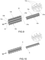
- FIG. 9 and 10 The production process of a velvet ribbon is well known per se and is diagrammatically shown in Figures 9 and 10 . More in detail, two textile ribbons, preferably edged in a longitudinal direction by selvedges 6, are tightly sewn together, until the surface between the two edges of the ribbon is filled with stitches. The two ribbons are then separated from each other by cutting the sewing threads at the gap existing therebetween. The cut sewing threads separate, creating a layer of free hairs (fibres) on one face of each ribbon, which are anchored to the ribbon (textile substrate) at the bottom thereof. The density of the free hair layer depends on the density of the stitches.
- the fibres 10 extend from the textile substrate 20 outwards with substantially the same length.
- the layer of fibres 10 has a substantially uniform height.
- such a length is between 0.5mm and 3mm, and even more preferably between 1.0mm and 1.30mm.
- the aforementioned fibres 10 are uniformly distributed on the textile substrate 20. Even more preferably, the aforementioned fibres 10 are uniformly distributed on the textile substrate 20 with a surface density between 80 and 130 fibres/mm2.
- fibres within the aforesaid count ranges allows to increase the mechanical strength of the fibres themselves, reducing the risk of accidental breakage of the fibres themselves and consequent dispersion thereof during the operations of taking biological samples.
- fibres within the aforesaid count ranges allows to reduce the incidence of intertwining fibres compared to the use of fibres with lower counts.
- the fibres 10 can be:
- the fibres 10 are made of polyamide, preferably nylon 6 or nylon 6,6.
- the aforesaid textile substrate 20 is fixed directly to the surface of the end portion 2a of the rod 2.
- the aforesaid textile substrate 20 is glued to the surface of the end portion 2a of the rod 2.
- a layer of adhesive 3 can form between the textile substrate 20 and the surface of the rod 2, which can partially penetrate the textile substrate 20.
- the adhesive does not go beyond the textile substrate 20 so as not to invade the layer of fibres 10 extending from the outer face 20a of the substrate 20 and which come into direct contact with the patient's body in use.
- the adhesive layer 3 can, however, come into contact with the bottom portions 10b of the fibres. This further contributes to stabilizing the fibres 10 on the swab 1, reducing the risk of accidental detachment of the fibres themselves.
- the substrate 20 to the rod 2 can be included, for example by heat or ultrasound, as a function of the material with which the substrate itself is made.
- gluing is the preferred method.
- the aforesaid textile substrate 20 can be made with threads:
- said textile substrate 20 consists of polyamide threads, preferably nylon 6 or nylon 6,6.
- the textile substrate 20 is made of the same material as the fibres 10, although different materials can also be used.
- the textile substrate 20 consists of threads having a count between 30 dtex and 120 dtex.
- the warp and weft threads can have the same count. However, it is possible to differentiate the count of the weft threads with respect to the warp threads. For example, it is possible to make a textile substrate in which the weft threads have a count of 33 dtex, while the warp threads have a count of 110 dtex.
- the aforesaid textile substrate 20 has a weight between 20 g/m2 and 600 g/m2.
- the weight of the substrate 20 is chosen as a function of the contribution in terms of absorption of the biological samples to be obtained from the substrate 20.
- the present invention also relates to a kit for taking and transporting biological samples.
- a kit for taking and transporting biological samples.
- Such a kit comprises a test-tube containing a culture medium (preferably liquid), and a swab 1 according to the invention, and in particular as described above.
- the present invention also relates to a method for making a swab 1 for taking biological samples according to the invention, and in particular as described above.
- the method comprises the following operating steps:
- the covering step c) is carried out by fixing the textile substrate 20 to the rod 2 at a second face 20b of the substrate 20, opposite said first face 20a, so that the fibres 10 extend orthogonally from the surface of the free end portion 2a of the rod 2 covered by the substrate, forming a layer of fibres 10 which extends all around the aforesaid free end portion 2a.
- the textile substrate 20 provided with fibres 10 consists of a velvet ribbon.
- the aforesaid textile substrate 20 is fixed to the rod 2 by gluing by application of an adhesive to said textile substrate 20 and/or to the rod 2.
- the substrate 20 is adhered to the portion of the rod to be coated by interposing a layer of glue/adhesive between the substrate and the rod.
- the method comprises a step d) of applying a glue on the second face 20b of said textile substrate 20.
- the application of the glue / adhesive is carried out before the covering step c).
- the adhesive/glue can be applied on the rod 2, rather than on the textile substrate. However, it is preferable to apply the adhesive on the substrate rather than on the rod 2 as this is not only operatively simpler but ensures a better and more precise fixing of the substrate on the rod.
- the aforesaid glue/adhesive is chosen with a sufficiently high viscosity as not to completely penetrate the textile substrate 20 and thereby not be absorbed by capillarity by the fibres 10 extending from the first face 20a of the substrate 20.
- the aforesaid textile substrate 20 is ribbon-shaped having a prevailing longitudinal direction of extension X, while the free end portion 2a of the rod 2 has a prevailing extension axis Y.
- the textile substrate 20 (in the form of a ribbon) is wound along the aforesaid prevailing longitudinal direction of extension X on said free end portion 2a of the rod 2 around the prevailing extension axis Y until it covers all said free end portion 2a.
- the winding may require a single turn, or several turns, for example according to a spiral pattern.
- the substrate 20 is wound around said free end portion 2a so that a portion 21 of the substrate 20 itself protrudes beyond the free end of the rod 2.
- the portion 21 of substrate protruding beyond the free end of the rod 2 is partially cut.
- the selvedge of the edge is cut, and the dimensions of the protruding portion are adapted to the portion of the rod still to be covered.
- the residual protruding strips are then forced to close radially on the free end 2a to form a continuous surface also at the free end of the rod 2.
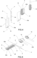
- the winding mode described above ( fig. 5 ) is particularly suitable for coating portions of rods with larger diameters.
- a portion of textile substrate 20 (in the form of a ribbon) is placed at the centre thereof on the end of the rod 2.
- the two symmetrical strips of the substrate are then folded on the rod 2 so as to form a cap which is then pressed so as to adhere to the rod itself.
- the excess ribbon (and in particular the selvedges of the edges) is cut along cutting lines parallel to the prevailing extension axis Y of the rod 2 and the remaining ribbon is made to adhere to the rod to obtain a continuous surface along said cutting lines.
- the winding mode just described ( fig. 4 ) is particularly suitable for coating portions of rods with smaller diameters.
- the method according to the invention can be automated and allow to make swabs in a simple manner, making them immediately available for packaging, unlike production by flocking which requires long drying times and subsequent cleaning of excess fibres.
- the swabs according to the invention allow a higher release of the sample, which can be estimated at about 10%-15% more.
- the swab according to the invention had the following features: - surface coated with fibres equal to 130 mm2; - textile substrate with a weight of 170 g/m2; warp threads 110 dtex; weft threads 33 dtex; protruding fibres 78 dtex and length 1.2 mm (extension with respect to the substrate); substrate and fibres made of 100% polyamide (nylon 6).
- the swab according to the invention had a surface coated with fibres equivalent to that of the flocked swab.
- the comparative test was carried out in two parts: in the first part the amount absorbed by the swabs was evaluated, while in the second part (immediately sequential to the first part) the amount released by the swabs was evaluated.
- Deionized water was taken from a container using a pipette and deposited in a dish. Several tests were conducted by varying the amount of water available in the dish and then by varying the amount absorbed by the swabs.
- the use of deionized water allows the density to be dependent only on temperature (and minimally) and the absorption to not be linked to the absorbed liquid/substrate affinity. Once the drop was placed on the dish, the amount in grams deposited was measured on a thousandth scale (division 1mg).
- the swab under examination was taken and, for a time of 5 seconds, an attempt was made to absorb the maximum amount of liquid by turning the swab around the drop. Once the swab was extracted, the remaining amount was measured in grams. The amount absorbed by the swab is equal to the difference between the deposited amount and the remaining amount. Differential measurement is a measurement which also has the advantage of being free from any absolute measurement error which the scale could have.
- the following procedure was carried out to evaluate the amount released by the swabs.
- a previously prepared piece of filter paper (50x50 mm squares) was placed on the scale and the scale was tared. Taking the swab just soaked in ionized water, it was rotated for 5 seconds around the filter paper while applying light pressure, in order to transfer the maximum amount of liquid from the swab to the filter paper. The entire surface of the filter paper was used. Also in this case, by means of differential measurement, the amount of liquid released by the swab was thus determined.
- the tests were conducted on three different volumes of water available on the dish: 50 ⁇ L, 100 ⁇ L and 200 ⁇ L.
- the volumes 50uL and 100 ⁇ L were chosen because they correspond to the volumes of bacterial suspension which are normally inoculated in quality control tests.
- the volume 200 ⁇ L was chosen to highlight how the trend of the absorption and release cycle stabilizes at infinite volume.
- Table A shown in Figure 11 , collects the data related to the comparative tests between the swab according to the invention and the flocked swab, carried out having a volume of water available on the dish equal to 50 ⁇ L.
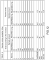
- Table B shown in Figure 12 , collects the data related to the comparative tests between the swab according to the invention and the flocked swab, carried out having a volume of water available on the dish equal to 100 ⁇ L.
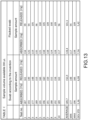
- Table C shown in Figure 13 , collects the data related to the comparative tests between the swab according to the invention and the flocked swab, carried out having a volume of water available on the dish equal to 200 ⁇ L.
- the comparative tests conducted highlight that the swab according to the invention has features and functionality comparable to the flocked swabs available on the market, which currently represent the standard in the microbiological field, especially as regards virological analyses.
- the tests highlighted a greater absorption capacity in absolute terms of the swab according to the invention with respect to flocked swabs, both as regards samples of 100 ⁇ L and 200 ⁇ L, and as regards samples of 50 ⁇ L.
- the comparative tests demonstrated that the swab according to the invention, over a period of a few seconds (time corresponding to clinical use), absorbs a certain amount of sample, and is then able to release a large part of this absorbed amount.
- a swab for taking biological samples according to the invention has at least a biological sample absorption and release capacity which is comparable to (if not even higher than) that of a flocked swab.
- the invention allows to obtain several advantages which have been explained in the description.
- the swab for taking biological samples according to the invention has a layer of fibres arranged orthogonally to the surface of the support rod and can be made in an operatively simpler manner than a flocked swab.
- the swab for taking biological samples according to the invention has a biological sample absorption and release capacity which is comparable to that of a flocked swab.
Landscapes
- Health & Medical Sciences (AREA)
- Life Sciences & Earth Sciences (AREA)
- Engineering & Computer Science (AREA)
- General Health & Medical Sciences (AREA)
- Veterinary Medicine (AREA)
- Heart & Thoracic Surgery (AREA)
- Biomedical Technology (AREA)
- Animal Behavior & Ethology (AREA)
- Public Health (AREA)
- Epidemiology (AREA)
- Vascular Medicine (AREA)
- Pathology (AREA)
- Medical Informatics (AREA)
- Molecular Biology (AREA)
- Surgery (AREA)
- Manufacturing & Machinery (AREA)
- Hematology (AREA)
- Sampling And Sample Adjustment (AREA)
Claims (19)
- Écouvillon pour prélever des échantillons biologiques comprenant une tige support (2) ayant une partie d'extrémité (2a) revêtue d'une couche de fibres (10), chaque fibre s'étendant en longueur orthogonalement à une surface de la tige de support (2) avec une partie d'extrémité libre correspondante (10a), dans lequel ladite couche de fibres (10) a des propriétés hydrophiles pour permettre l'absorption d'échantillons biologiques, dans lequel chacune desdites fibres (10) est ancrée mécaniquement, au niveau d'une partie inférieure (10b), à un substrat textile (20) qui est à son tour fixé à une surface de la partie d'extrémité (2a) de ladite tige, caractérisé en ce que lesdites fibres (10) ont un titre compris entre 60 dtex et 90 dtex.
- Écouvillon selon la revendication 1, dans lequel chacune desdites fibres (10) traverse ledit substrat textile (20) de telle sorte que la partie d'extrémité libre respective (10a) s'étend orthogonalement depuis une face extérieure (20a) dudit substrat textile (20), et la partie inférieure respective (10b) s'étend depuis une face intérieure (20b) dudit substrat textile (20), opposée à ladite face extérieure (20a), et est positionnée entre ladite face intérieure (20b) et la surface de la partie d'extrémité (2a) de ladite tige (2).
- Écouvillon selon la revendication 2, dans lequel lesdites fibres (10) sont raccordées par paires au niveau des parties inférieures respectives (10b) pour former un corps unique.
- Écouvillon selon l'une des revendications précédentes, dans lequel ledit substrat textile (20) et lesdites fibres (10) sont raccordés à ladite partie d'extrémité (2a) de ladite tige sous forme d'un corps préassemblé.
- Écouvillon selon la revendication 4, dans lequel ledit corps préassemblé est constitué d'un ruban de velours.
- Écouvillon selon l'une des revendications précédentes, dans lequel lesdites fibres (10) s'étendent depuis ledit substrat textile (20) vers l'extérieur sensiblement avec la même longueur, ladite longueur étant de préférence comprise entre 0,5 mm et 3 mm, et de manière encore plus préférée entre 1,0 mm et 1,30 mm.
- Écouvillon selon l'une des revendications précédentes, dans lequel lesdites fibres (10) sont réparties uniformément sur ledit substrat textile (20), de préférence selon une densité surfacique comprise entre 80 et 130 fibres/mm2.
- Écouvillon selon l'une des revendications précédentes, dans lequel ledit substrat textile (20) est attaché directement à la surface de la partie d'extrémité (2a) de ladite tige (2).
- Écouvillon selon l'une des revendications précédentes, dans lequel ledit substrat textile (20) est constitué de fils ayant un titre compris entre 30 dtex et 120 dtex.
- Écouvillon selon l'une des revendications précédentes, dans lequel ledit substrat textile (20) a un grammage compris entre 20 g/m2 et 600 g/m2.
- Kit de prélèvement et de transport d'échantillons biologiques, caractérisé en ce qu'il comprend une éprouvette contenant un milieu de culture, et un écouvillon (1) selon l'une des revendications précédentes.
- Procédé de fabrication d'un écouvillon (1) destiné à prélever des échantillons biologiques selon l'une des revendications 1 à 10, ledit procédé comprenant les étapes opératoires suivantes consistant à :(a) fournir une tige de support (2) comprenant une partie d'extrémité libre (2a) ;(b) fournir un substrat textile (20) comprenant une première face (20a) depuis laquelle une pluralité de fibres (10) ancrées mécaniquement audit substrat textile (2) s'étendent orthogonalement ; et(c) revêtir la partie d'extrémité libre (2a) de ladite tige (2) avec ledit substrat textile (20) en fixant ledit substrat textile (20) à ladite tige (2) au niveau d'une seconde face (20b), opposée à ladite première face (20a), de sorte que lesdites fibres (10) s'étendent orthogonalement depuis la surface de la partie d'extrémité (2a) de ladite tige (2) en formant une couche de fibres (10) qui s'étend tout autour de ladite partie d'extrémité (2a).
- Procédé selon la revendication 12, dans lequel ledit substrat textile (20) comportant les fibres (10) est constitué d'un ruban de velours.
- Procédé selon la revendication 12 ou 13, dans lequel ledit substrat textile (20) est fixé à ladite tige (2) par collage par application d'un adhésif sur ledit substrat textile (20) et/ou sur ladite tige (2).
- Procédé selon la revendication 14, comprenant une étape (d) consistant à appliquer un adhésif sur ladite seconde face (20b) dudit substrat textile (20) avant ladite étape de revêtement (c).
- Procédé selon la revendication 14 ou 15, dans lequel ledit adhésif est choisi avec une viscosité suffisamment élevée pour ne pas pénétrer complètement dans le substrat textile (20) et ainsi ne pas être absorbé par capillarité par les fibres (10) s'étendant depuis la première face (20a) dudit substrat (20).
- Procédé selon l'une des revendications 12 à 16, dans lequel ledit substrat (20) est en forme de ruban ayant une direction d'extension longitudinale dominante (X) et la partie d'extrémité (2a) de ladite tige (2) a un axe d'extension dominant (Y), et dans lequel, pendant ladite étape c) de revêtement, ledit substrat (20) est enroulé le long de ladite direction d'extension longitudinale dominante (X) sur ladite partie d'extrémité (2a) de ladite tige (2) autour dudit axe d'extension dominant (Y) jusqu'à ce qu'il recouvre toute ladite partie d'extrémité (2a).
- Procédé selon la revendication 17, dans lequel ledit substrat (20) est enroulé autour de ladite partie d'extrémité (2a) de telle sorte qu'une partie du substrat lui-même (20) fait saillie au-delà de l'extrémité libre de la tige (2), et dans lequel ladite partie de substrat faisant saillie au-delà de l'extrémité libre de la tige (2) est partiellement découpée et les bandes en saillie résiduelles sont forcées de se refermer radialement sur l'extrémité libre (2a) pour former une surface continue également au niveau de l'extrémité libre de la tige (2).
- Procédé selon l'une des revendications 12 à 16, dans lequel ledit substrat (20) est en forme de ruban ayant une direction d'extension longitudinale dominante (X) et la partie d'extrémité (2a) de ladite tige (2) a un axe d'extension dominant (Y), et dans lequel, lors de ladite étape c) de revêtement d'une partie dudit ruban (20), celui-ci est placé au niveau de son centre sur l'extrémité de la tige (2) et les deux bandes symétriques sont ensuite pliées sur la tige (2) de manière à former un capuchon qui est ensuite comprimé de manière à adhérer à la tige, dans lequel de préférence le ruban en excès est coupé le long de lignes de découpe parallèles à l'axe d'extension dominant (Y) de la tige (2) et le ruban restant est amené à adhérer à la tige pour obtenir une surface continue le long desdites lignes de découpe.
Applications Claiming Priority (2)
| Application Number | Priority Date | Filing Date | Title |
|---|---|---|---|
| IT102020000011683A IT202000011683A1 (it) | 2020-05-20 | 2020-05-20 | Tampone per il prelievo di campioni biologici e metodo per realizzare tale tampone |
| PCT/IB2021/054265 WO2021234564A1 (fr) | 2020-05-20 | 2021-05-18 | Écouvillon pour la prise d'échantillons biologiques et procédé de fabrication d'un tel écouvillon |
Publications (3)
| Publication Number | Publication Date |
|---|---|
| EP4153063A1 EP4153063A1 (fr) | 2023-03-29 |
| EP4153063C0 EP4153063C0 (fr) | 2024-02-28 |
| EP4153063B1 true EP4153063B1 (fr) | 2024-02-28 |
Family
ID=72178922
Family Applications (1)
| Application Number | Title | Priority Date | Filing Date |
|---|---|---|---|
| EP21731292.5A Active EP4153063B1 (fr) | 2020-05-20 | 2021-05-18 | Écouvillon pour la prise d'échantillons biologiques et procédé de fabrication d'un tel écouvillon |
Country Status (4)
| Country | Link |
|---|---|
| US (1) | US20230172762A1 (fr) |
| EP (1) | EP4153063B1 (fr) |
| IT (1) | IT202000011683A1 (fr) |
| WO (1) | WO2021234564A1 (fr) |
Families Citing this family (4)
| Publication number | Priority date | Publication date | Assignee | Title |
|---|---|---|---|---|
| CA3177116A1 (fr) * | 2020-05-01 | 2021-11-04 | Richard Novak | Ecouvillon de prelevement d'echantillon |
| MX2023010932A (es) * | 2021-03-18 | 2023-12-14 | Bernard Marie Chaffringeon | Aplicador de torunda rompible para uso con un paño de muestreo y un kit de torunda. |
| CN116448494A (zh) * | 2022-01-10 | 2023-07-18 | 浙江东方基因生物制品股份有限公司 | 一种生产制造收集样本的收集器的设备 |
| US12082788B1 (en) * | 2023-08-03 | 2024-09-10 | King Faisal University | Gingival crevicular fluid absorbing brush |
Family Cites Families (9)
| Publication number | Priority date | Publication date | Assignee | Title |
|---|---|---|---|---|
| IT1272598B (it) | 1993-09-09 | 1997-06-26 | Copan Italia Spa | Dispositivo per il prelievo e trasporto di campioni in vitro principalmente per uso diagnostico |
| JP3895212B2 (ja) * | 2002-04-12 | 2007-03-22 | エヌアイ帝人商事株式会社 | 清掃用立毛布帛およびモップ |
| ITMI20030643A1 (it) | 2003-04-01 | 2004-10-02 | Copan Innovation Ltd | Tampone per il prelievo di campioni biologici |
| US8323211B2 (en) * | 2006-06-01 | 2012-12-04 | Daniel Larkin | Sexually transmitted infection sampling device |
| US20200093467A1 (en) * | 2018-09-20 | 2020-03-26 | Histologics Llc | Scrape and sweep frictional tissue sampling and collection method and device |
| DE102012214640A1 (de) * | 2012-08-17 | 2014-02-20 | Aesculap Ag | Beflockter medizinischer Schlauch |
| JP6128790B2 (ja) * | 2012-10-15 | 2017-05-17 | 株式会社リブドゥコーポレーション | 吸収性物品 |
| JP5686853B2 (ja) * | 2013-06-13 | 2015-03-18 | デンカ生研株式会社 | 生物学的検体の採取用スワブ、該スワブの製造方法及び該スワブを用いたキット |
| US20210302446A1 (en) * | 2018-07-11 | 2021-09-30 | Abraham Joy | Methods and devices that change color to indicate the presence of opioids and other narcotics |
-
2020
- 2020-05-20 IT IT102020000011683A patent/IT202000011683A1/it unknown
-
2021
- 2021-05-18 EP EP21731292.5A patent/EP4153063B1/fr active Active
- 2021-05-18 WO PCT/IB2021/054265 patent/WO2021234564A1/fr not_active Ceased
- 2021-05-18 US US17/924,098 patent/US20230172762A1/en active Pending
Also Published As
| Publication number | Publication date |
|---|---|
| EP4153063A1 (fr) | 2023-03-29 |
| IT202000011683A1 (it) | 2021-11-20 |
| EP4153063C0 (fr) | 2024-02-28 |
| US20230172762A1 (en) | 2023-06-08 |
| WO2021234564A1 (fr) | 2021-11-25 |
Similar Documents
| Publication | Publication Date | Title |
|---|---|---|
| EP4153063B1 (fr) | Écouvillon pour la prise d'échantillons biologiques et procédé de fabrication d'un tel écouvillon | |
| US20220265251A1 (en) | Swab for collecting biological specimens | |
| JP7183340B2 (ja) | 生物学的な液体サンプルの収集、搬送のための検体採取器及び検体採取器の製造方法 | |
| EP3014240B1 (fr) | Ecouvillon floqué et procédé de collecte et de transfert d'échantillons de matière biologique | |
| ITMI20110004A1 (it) | Procedimento per realizzare un dispositivo per il prelievo ed il trasferimento di campioni per biologia molecolare | |
| CN101147057B (zh) | 用于分析体液的测试元件 | |
| US9023292B2 (en) | Blood sampling device comprising at least one filter | |
| JP5757371B2 (ja) | 液体検査用具 | |
| CA2179567C (fr) | Element et systeme pour prelever, transporter et stocker des matieres a echantillonner pour analyse | |
| ITMI20121603A1 (it) | Dispositivo e metodo per il prelievo ed il trasferimento di campioni di materiale biologico | |
| KR101181396B1 (ko) | 검체 용기 | |
| JP2002527726A (ja) | 生体サンプルの採取装置及び採取方法 | |
| JP2000514177A (ja) | 被検サンプルを採集し輸送するための物品および被検物質の測定方法 | |
| JP2014083386A (ja) | 生体物質試料を採取及び移動させるための器具並びにその使用方法 | |
| JP5290131B2 (ja) | 生物学的検体の採取用スワブ、該スワブの製造方法及び該スワブを用いたキット | |
| WO2008012566A2 (fr) | Dispositif, système et procédé de collecte de liquide | |
| JP2016125875A (ja) | サンプルパッドおよびそれを用いた液体試料検査具 | |
| JP5686853B2 (ja) | 生物学的検体の採取用スワブ、該スワブの製造方法及び該スワブを用いたキット | |
| US5460781A (en) | Hemoglobin sampler | |
| JP2023543412A (ja) | 検体採取スティック | |
| CN120882396A (zh) | 月经垫收集系统 | |
| WO2018008672A1 (fr) | Pointe de prélèvement d'échantillon, récipient de préparation d'échantillon, et kit de préparation d'échantillon | |
| US12496576B2 (en) | Apparatus and method for collecting liquid samples | |
| US8263020B2 (en) | Analytical test element and process for its production | |
| CN208922633U (zh) | 一种吸液指示部件和液体检测装置 |
Legal Events
| Date | Code | Title | Description |
|---|---|---|---|
| STAA | Information on the status of an ep patent application or granted ep patent |
Free format text: STATUS: UNKNOWN |
|
| STAA | Information on the status of an ep patent application or granted ep patent |
Free format text: STATUS: THE INTERNATIONAL PUBLICATION HAS BEEN MADE |
|
| PUAI | Public reference made under article 153(3) epc to a published international application that has entered the european phase |
Free format text: ORIGINAL CODE: 0009012 |
|
| STAA | Information on the status of an ep patent application or granted ep patent |
Free format text: STATUS: REQUEST FOR EXAMINATION WAS MADE |
|
| 17P | Request for examination filed |
Effective date: 20221104 |
|
| AK | Designated contracting states |
Kind code of ref document: A1 Designated state(s): AL AT BE BG CH CY CZ DE DK EE ES FI FR GB GR HR HU IE IS IT LI LT LU LV MC MK MT NL NO PL PT RO RS SE SI SK SM TR |
|
| DAV | Request for validation of the european patent (deleted) | ||
| DAX | Request for extension of the european patent (deleted) | ||
| GRAP | Despatch of communication of intention to grant a patent |
Free format text: ORIGINAL CODE: EPIDOSNIGR1 |
|
| STAA | Information on the status of an ep patent application or granted ep patent |
Free format text: STATUS: GRANT OF PATENT IS INTENDED |
|
| RIC1 | Information provided on ipc code assigned before grant |
Ipc: A61F 13/38 20060101ALN20230907BHEP Ipc: A61B 10/02 20060101ALI20230907BHEP Ipc: A61B 10/00 20060101AFI20230907BHEP |
|
| INTG | Intention to grant announced |
Effective date: 20230922 |
|
| RIC1 | Information provided on ipc code assigned before grant |
Ipc: A61F 13/38 20060101ALN20230908BHEP Ipc: A61B 10/02 20060101ALI20230908BHEP Ipc: A61B 10/00 20060101AFI20230908BHEP |
|
| GRAS | Grant fee paid |
Free format text: ORIGINAL CODE: EPIDOSNIGR3 |
|
| GRAA | (expected) grant |
Free format text: ORIGINAL CODE: 0009210 |
|
| STAA | Information on the status of an ep patent application or granted ep patent |
Free format text: STATUS: THE PATENT HAS BEEN GRANTED |
|
| AK | Designated contracting states |
Kind code of ref document: B1 Designated state(s): AL AT BE BG CH CY CZ DE DK EE ES FI FR GB GR HR HU IE IS IT LI LT LU LV MC MK MT NL NO PL PT RO RS SE SI SK SM TR |
|
| REG | Reference to a national code |
Ref country code: GB Ref legal event code: FG4D |
|
| REG | Reference to a national code |
Ref country code: CH Ref legal event code: EP |
|
| REG | Reference to a national code |
Ref country code: DE Ref legal event code: R096 Ref document number: 602021009902 Country of ref document: DE |
|
| REG | Reference to a national code |
Ref country code: IE Ref legal event code: FG4D |
|
| U01 | Request for unitary effect filed |
Effective date: 20240312 |
|
| U07 | Unitary effect registered |
Designated state(s): AT BE BG DE DK EE FI FR IT LT LU LV MT NL PT SE SI Effective date: 20240321 |
|
| U20 | Renewal fee for the european patent with unitary effect paid |
Year of fee payment: 4 Effective date: 20240423 |
|
| PG25 | Lapsed in a contracting state [announced via postgrant information from national office to epo] |
Ref country code: IS Free format text: LAPSE BECAUSE OF FAILURE TO SUBMIT A TRANSLATION OF THE DESCRIPTION OR TO PAY THE FEE WITHIN THE PRESCRIBED TIME-LIMIT Effective date: 20240628 |
|
| PG25 | Lapsed in a contracting state [announced via postgrant information from national office to epo] |
Ref country code: GR Free format text: LAPSE BECAUSE OF FAILURE TO SUBMIT A TRANSLATION OF THE DESCRIPTION OR TO PAY THE FEE WITHIN THE PRESCRIBED TIME-LIMIT Effective date: 20240529 |
|
| PG25 | Lapsed in a contracting state [announced via postgrant information from national office to epo] |
Ref country code: HR Free format text: LAPSE BECAUSE OF FAILURE TO SUBMIT A TRANSLATION OF THE DESCRIPTION OR TO PAY THE FEE WITHIN THE PRESCRIBED TIME-LIMIT Effective date: 20240228 Ref country code: RS Free format text: LAPSE BECAUSE OF FAILURE TO SUBMIT A TRANSLATION OF THE DESCRIPTION OR TO PAY THE FEE WITHIN THE PRESCRIBED TIME-LIMIT Effective date: 20240528 |
|
| PG25 | Lapsed in a contracting state [announced via postgrant information from national office to epo] |
Ref country code: ES Free format text: LAPSE BECAUSE OF FAILURE TO SUBMIT A TRANSLATION OF THE DESCRIPTION OR TO PAY THE FEE WITHIN THE PRESCRIBED TIME-LIMIT Effective date: 20240228 |
|
| PG25 | Lapsed in a contracting state [announced via postgrant information from national office to epo] |
Ref country code: RS Free format text: LAPSE BECAUSE OF FAILURE TO SUBMIT A TRANSLATION OF THE DESCRIPTION OR TO PAY THE FEE WITHIN THE PRESCRIBED TIME-LIMIT Effective date: 20240528 Ref country code: NO Free format text: LAPSE BECAUSE OF FAILURE TO SUBMIT A TRANSLATION OF THE DESCRIPTION OR TO PAY THE FEE WITHIN THE PRESCRIBED TIME-LIMIT Effective date: 20240528 Ref country code: IS Free format text: LAPSE BECAUSE OF FAILURE TO SUBMIT A TRANSLATION OF THE DESCRIPTION OR TO PAY THE FEE WITHIN THE PRESCRIBED TIME-LIMIT Effective date: 20240628 Ref country code: HR Free format text: LAPSE BECAUSE OF FAILURE TO SUBMIT A TRANSLATION OF THE DESCRIPTION OR TO PAY THE FEE WITHIN THE PRESCRIBED TIME-LIMIT Effective date: 20240228 Ref country code: GR Free format text: LAPSE BECAUSE OF FAILURE TO SUBMIT A TRANSLATION OF THE DESCRIPTION OR TO PAY THE FEE WITHIN THE PRESCRIBED TIME-LIMIT Effective date: 20240529 Ref country code: ES Free format text: LAPSE BECAUSE OF FAILURE TO SUBMIT A TRANSLATION OF THE DESCRIPTION OR TO PAY THE FEE WITHIN THE PRESCRIBED TIME-LIMIT Effective date: 20240228 |
|
| PG25 | Lapsed in a contracting state [announced via postgrant information from national office to epo] |
Ref country code: PL Free format text: LAPSE BECAUSE OF FAILURE TO SUBMIT A TRANSLATION OF THE DESCRIPTION OR TO PAY THE FEE WITHIN THE PRESCRIBED TIME-LIMIT Effective date: 20240228 |
|
| PG25 | Lapsed in a contracting state [announced via postgrant information from national office to epo] |
Ref country code: PL Free format text: LAPSE BECAUSE OF FAILURE TO SUBMIT A TRANSLATION OF THE DESCRIPTION OR TO PAY THE FEE WITHIN THE PRESCRIBED TIME-LIMIT Effective date: 20240228 |
|
| PG25 | Lapsed in a contracting state [announced via postgrant information from national office to epo] |
Ref country code: SM Free format text: LAPSE BECAUSE OF FAILURE TO SUBMIT A TRANSLATION OF THE DESCRIPTION OR TO PAY THE FEE WITHIN THE PRESCRIBED TIME-LIMIT Effective date: 20240228 |
|
| PG25 | Lapsed in a contracting state [announced via postgrant information from national office to epo] |
Ref country code: CZ Free format text: LAPSE BECAUSE OF FAILURE TO SUBMIT A TRANSLATION OF THE DESCRIPTION OR TO PAY THE FEE WITHIN THE PRESCRIBED TIME-LIMIT Effective date: 20240228 |
|
| PG25 | Lapsed in a contracting state [announced via postgrant information from national office to epo] |
Ref country code: SK Free format text: LAPSE BECAUSE OF FAILURE TO SUBMIT A TRANSLATION OF THE DESCRIPTION OR TO PAY THE FEE WITHIN THE PRESCRIBED TIME-LIMIT Effective date: 20240228 |
|
| PG25 | Lapsed in a contracting state [announced via postgrant information from national office to epo] |
Ref country code: SM Free format text: LAPSE BECAUSE OF FAILURE TO SUBMIT A TRANSLATION OF THE DESCRIPTION OR TO PAY THE FEE WITHIN THE PRESCRIBED TIME-LIMIT Effective date: 20240228 Ref country code: SK Free format text: LAPSE BECAUSE OF FAILURE TO SUBMIT A TRANSLATION OF THE DESCRIPTION OR TO PAY THE FEE WITHIN THE PRESCRIBED TIME-LIMIT Effective date: 20240228 Ref country code: RO Free format text: LAPSE BECAUSE OF FAILURE TO SUBMIT A TRANSLATION OF THE DESCRIPTION OR TO PAY THE FEE WITHIN THE PRESCRIBED TIME-LIMIT Effective date: 20240228 Ref country code: CZ Free format text: LAPSE BECAUSE OF FAILURE TO SUBMIT A TRANSLATION OF THE DESCRIPTION OR TO PAY THE FEE WITHIN THE PRESCRIBED TIME-LIMIT Effective date: 20240228 |
|
| REG | Reference to a national code |
Ref country code: DE Ref legal event code: R097 Ref document number: 602021009902 Country of ref document: DE |
|
| REG | Reference to a national code |
Ref country code: CH Ref legal event code: PL |
|
| PLBE | No opposition filed within time limit |
Free format text: ORIGINAL CODE: 0009261 |
|
| STAA | Information on the status of an ep patent application or granted ep patent |
Free format text: STATUS: NO OPPOSITION FILED WITHIN TIME LIMIT |
|
| PG25 | Lapsed in a contracting state [announced via postgrant information from national office to epo] |
Ref country code: MC Free format text: LAPSE BECAUSE OF FAILURE TO SUBMIT A TRANSLATION OF THE DESCRIPTION OR TO PAY THE FEE WITHIN THE PRESCRIBED TIME-LIMIT Effective date: 20240228 |
|
| PG25 | Lapsed in a contracting state [announced via postgrant information from national office to epo] |
Ref country code: MC Free format text: LAPSE BECAUSE OF FAILURE TO SUBMIT A TRANSLATION OF THE DESCRIPTION OR TO PAY THE FEE WITHIN THE PRESCRIBED TIME-LIMIT Effective date: 20240228 Ref country code: CH Free format text: LAPSE BECAUSE OF NON-PAYMENT OF DUE FEES Effective date: 20240531 |
|
| 26N | No opposition filed |
Effective date: 20241129 |
|
| PG25 | Lapsed in a contracting state [announced via postgrant information from national office to epo] |
Ref country code: IE Free format text: LAPSE BECAUSE OF NON-PAYMENT OF DUE FEES Effective date: 20240518 |
|
| U20 | Renewal fee for the european patent with unitary effect paid |
Year of fee payment: 5 Effective date: 20250422 |
|
| PG25 | Lapsed in a contracting state [announced via postgrant information from national office to epo] |
Ref country code: CY Free format text: LAPSE BECAUSE OF FAILURE TO SUBMIT A TRANSLATION OF THE DESCRIPTION OR TO PAY THE FEE WITHIN THE PRESCRIBED TIME-LIMIT; INVALID AB INITIO Effective date: 20210518 |
|
| PG25 | Lapsed in a contracting state [announced via postgrant information from national office to epo] |
Ref country code: HU Free format text: LAPSE BECAUSE OF FAILURE TO SUBMIT A TRANSLATION OF THE DESCRIPTION OR TO PAY THE FEE WITHIN THE PRESCRIBED TIME-LIMIT; INVALID AB INITIO Effective date: 20210518 |
|
| GBPC | Gb: european patent ceased through non-payment of renewal fee |
Effective date: 20250518 |
|
| PG25 | Lapsed in a contracting state [announced via postgrant information from national office to epo] |
Ref country code: GB Free format text: LAPSE BECAUSE OF NON-PAYMENT OF DUE FEES Effective date: 20250518 |
|
| U20 | Renewal fee for the european patent with unitary effect paid |
Year of fee payment: 6 Effective date: 20260325 |