EP4154777B1 - Antriebsvorrichtung mit uni- oder bidirektionaler drehung - Google Patents
Antriebsvorrichtung mit uni- oder bidirektionaler drehung Download PDFInfo
- Publication number
- EP4154777B1 EP4154777B1 EP22195792.1A EP22195792A EP4154777B1 EP 4154777 B1 EP4154777 B1 EP 4154777B1 EP 22195792 A EP22195792 A EP 22195792A EP 4154777 B1 EP4154777 B1 EP 4154777B1
- Authority
- EP
- European Patent Office
- Prior art keywords
- rotation
- drive device
- coupling
- coupling member
- drive
- Prior art date
- Legal status (The legal status is an assumption and is not a legal conclusion. Google has not performed a legal analysis and makes no representation as to the accuracy of the status listed.)
- Active
Links
Images




Classifications
-
- A—HUMAN NECESSITIES
- A47—FURNITURE; DOMESTIC ARTICLES OR APPLIANCES; COFFEE MILLS; SPICE MILLS; SUCTION CLEANERS IN GENERAL
- A47J—KITCHEN EQUIPMENT; COFFEE MILLS; SPICE MILLS; APPARATUS FOR MAKING BEVERAGES
- A47J43/00—Implements for preparing or holding food, not provided for in other groups of this subclass
- A47J43/04—Machines for domestic use not covered elsewhere, e.g. for grinding, mixing, stirring, kneading, emulsifying, whipping or beating foodstuffs, e.g. power-driven
- A47J43/07—Parts or details, e.g. mixing tools, whipping tools
- A47J43/08—Driving mechanisms
- A47J43/082—Driving mechanisms for machines with tools driven from the upper side
-
- A—HUMAN NECESSITIES
- A47—FURNITURE; DOMESTIC ARTICLES OR APPLIANCES; COFFEE MILLS; SPICE MILLS; SUCTION CLEANERS IN GENERAL
- A47J—KITCHEN EQUIPMENT; COFFEE MILLS; SPICE MILLS; APPARATUS FOR MAKING BEVERAGES
- A47J43/00—Implements for preparing or holding food, not provided for in other groups of this subclass
- A47J43/04—Machines for domestic use not covered elsewhere, e.g. for grinding, mixing, stirring, kneading, emulsifying, whipping or beating foodstuffs, e.g. power-driven
- A47J43/044—Machines for domestic use not covered elsewhere, e.g. for grinding, mixing, stirring, kneading, emulsifying, whipping or beating foodstuffs, e.g. power-driven with tools driven from the top side
-
- A—HUMAN NECESSITIES
- A47—FURNITURE; DOMESTIC ARTICLES OR APPLIANCES; COFFEE MILLS; SPICE MILLS; SUCTION CLEANERS IN GENERAL
- A47J—KITCHEN EQUIPMENT; COFFEE MILLS; SPICE MILLS; APPARATUS FOR MAKING BEVERAGES
- A47J43/00—Implements for preparing or holding food, not provided for in other groups of this subclass
- A47J43/10—Egg-whisks; Cream-beaters, i.e. hand implements or hand-driven devices
- A47J43/1006—Hand-driven mixing devices with rotating tools, e.g. sticking out from the bottom of the mixing receptacle; with rotating bowls; with an additional function
- A47J43/105—Hand-driven mixing devices with rotating tools, e.g. sticking out from the bottom of the mixing receptacle; with rotating bowls; with an additional function the rotating tools being driven by a reciprocating member, e.g. by a rack-and-pinion mechanism or by a tangentially-pulled rope
-
- B—PERFORMING OPERATIONS; TRANSPORTING
- B01—PHYSICAL OR CHEMICAL PROCESSES OR APPARATUS IN GENERAL
- B01F—MIXING, e.g. DISSOLVING, EMULSIFYING OR DISPERSING
- B01F35/00—Accessories for mixers; Auxiliary operations or auxiliary devices; Parts or details of general application
- B01F35/30—Driving arrangements; Transmissions; Couplings; Brakes
- B01F35/31—Couplings
-
- B—PERFORMING OPERATIONS; TRANSPORTING
- B01—PHYSICAL OR CHEMICAL PROCESSES OR APPARATUS IN GENERAL
- B01F—MIXING, e.g. DISSOLVING, EMULSIFYING OR DISPERSING
- B01F35/00—Accessories for mixers; Auxiliary operations or auxiliary devices; Parts or details of general application
- B01F35/30—Driving arrangements; Transmissions; Couplings; Brakes
- B01F35/32—Driving arrangements
- B01F35/32005—Type of drive
- B01F35/3202—Hand driven
-
- B—PERFORMING OPERATIONS; TRANSPORTING
- B01—PHYSICAL OR CHEMICAL PROCESSES OR APPARATUS IN GENERAL
- B01F—MIXING, e.g. DISSOLVING, EMULSIFYING OR DISPERSING
- B01F35/00—Accessories for mixers; Auxiliary operations or auxiliary devices; Parts or details of general application
- B01F35/30—Driving arrangements; Transmissions; Couplings; Brakes
- B01F35/32—Driving arrangements
- B01F35/321—Disposition of the drive
- B01F35/3214—Disposition of the drive at the upper side of the axis, e.g. driving the stirrer from the top of a receptacle
-
- B—PERFORMING OPERATIONS; TRANSPORTING
- B01—PHYSICAL OR CHEMICAL PROCESSES OR APPARATUS IN GENERAL
- B01F—MIXING, e.g. DISSOLVING, EMULSIFYING OR DISPERSING
- B01F35/00—Accessories for mixers; Auxiliary operations or auxiliary devices; Parts or details of general application
- B01F35/30—Driving arrangements; Transmissions; Couplings; Brakes
- B01F35/33—Transmissions; Means for modifying the speed or direction of rotation
- B01F35/332—Transmissions; Means for modifying the speed or direction of rotation alternately changing the direction of rotation
-
- B—PERFORMING OPERATIONS; TRANSPORTING
- B01—PHYSICAL OR CHEMICAL PROCESSES OR APPARATUS IN GENERAL
- B01F—MIXING, e.g. DISSOLVING, EMULSIFYING OR DISPERSING
- B01F2101/00—Mixing characterised by the nature of the mixed materials or by the application field
- B01F2101/1805—Kitchen, household equipment for mixing
Definitions
- the present invention relates to the field of manual rope drive devices for culinary cutting, mixing or grinding appliances.
- Numerous mixing or chopping culinary appliances are known from the state of the art. We distinguish in particular between electrical devices in which a drive device using an electric motor rotates a tool which can be a knife or a mixing arm.
- the main advantage of electric drive devices is that they offer a constant torque and a variable rotation speed which is a direct function of the rotation speed of the electric motor.
- the document DE 580073 describes a mixing and beating machine, for bakeries, with a continuously variable speed change. Although this machine allows for gear shifting, the gearbox is designed for a machine that must be shifted manually. The operator must therefore adjust the speed manually by operating a gearbox.
- the document FR 2 532 540 describes a device for making and mixing sauces.
- the drive of this device has a gear train to change the rotational speed, the gear ratio is fixed and the torque can only be varied by varying the externally applied force.
- the device for manually chopping food described in the document WO 2004/073474 , which also has a gear in a cover which rotates a cutting tool in the form of a set of knives.
- the user can activate moving parts of the rope drive unit.
- a rope drum is driven directly by the rope and is positively coupled into the connection member in one direction of rotation and decoupled in the other direction of rotation from the connection member.
- An at least two-stage transmission is formed between the rope drive unit and the rotating connection member, which is switchable between a low-speed cutting mode and a precise cutting mode with a higher speed compared to to low speed cutting mode.
- a return spring is designed to retract the rope pulled by the user and thus prepare for the next pulling movement.
- the mixer drive shaft at reduced speed and increased torque if the texture of the mixture turns out to be so dense that the return of the rope would be prevented by lack of force of the return spring. It is also possible to use the high rotation speed with the cutting drive shaft if the materials are thin enough to offer less resistance and allow the knives to move back without causing a blockage that would prevent the rope from retract.
- the coupling member is movable between a first position in which the coupling member is adapted to transmit a movement in a single direction of rotation of the rotation subassembly and a second position in which the coupling member coupling is adapted to transmit a movement in two directions of rotation of the rotation subassembly.
- the coupling member may comprise a ratchet wheel portion making it possible to transmit movement in a single direction of rotation.
- the drive device may comprise a first coupling element connected in rotation to the rotation subassembly and adapted to be coupled to the ratchet wheel portion of the coupling member.
- the coupling member may comprise a portion of a dog wheel making it possible to transmit movement in two directions of rotation.
- the drive device may comprise a second coupling element adapted to be coupled to the dog wheel portion of the coupling member, to be connected in rotation to the drive member.
- the Drive Device may comprise a two-stage gear interposed between the first coupling element and second coupling element, to modify a torque and a rotational speed of a movement transmitted from the first coupling element to the second element coupling, when the second coupling element is coupled to the dog wheel portion of the coupling member.
- the coupling member can be movable in translation between the first position and the second position.
- the drive device may comprise a lever making it possible to move the coupling member in translation between the first position and the second position.
- At least one elastic member can exert a force on the lever to automatically position it in the first position.
- An actuator may be adapted to position and maintain the lever in the second position.
- the rotation subassembly may comprise a reel comprising a rope and a return spring, the reel rotating the rotation subassembly.
- the invention relates to a culinary mixer or grinder appliance comprising a drive device according to any one of the preceding claims.
- the culinary appliance may include a bowl and a lid adapted to close the bowl, the training device may be contained in the lid.
- the culinary appliance may include a removable food working arm for mixing or grinding, the food working arm being connected to the driver of the training device.
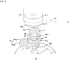
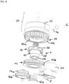
- the invention proposes a rotational drive device 1 for a culinary mixer or grinder.
- the coupling member 6 is movable between a first position in which the coupling member 6 is adapted to transmit a movement in a single direction of rotation of the rotation subassembly 29 and a second position in which the coupling member coupling 6 is adapted to transmit a movement in two directions of rotation of the rotation subassembly 29.
- the coupling member 6 very advantageously allows the transmission mode to be changed to allow unidirectional rotation or bidirectional rotation.
- a simple movement of the coupling member 6 makes it possible to move from a first unidirectional rotation position to a second bidirectional rotation position and vice versa.
- This arrangement very advantageously allows the training device 1 to be particularly versatile and to be able to be used both for chopping and for mix. Indeed, for chopping large elements, we will often prefer a unidirectional rotation, and for mixing we will often prefer a bidirectional rotation.
- the training device 1 comprises a rotation subassembly 29.
- the rotation subassembly 29 is a reel comprising a rope 24, one end of which is wound around a drive wheel 22 and the other end of which is connected to a handle, and a return spring 26
- the rotation subassembly 29 advantageously comprises a winding drum or a drive wheel 22 comprising a groove where the rope 24 is housed while winding around the axis of rotation.
- the drive wheel 22 is a known element which rotates thanks to the traction on a rope 24. When a user pulls on the handle connected to the rope 24, it is completely unwound, then the return spring 26 allows the drive wheel 22 to rotate in the opposite direction and thus rewind the rope 24. It should be noted that the rotation generated by the return spring 26 is opposite to the rotation generated by the rope 24.
- the drive wheel 22 of the drive device 1 has a cavity intended to receive the return spring 26.
- the rope 24 is wound in the groove of the drive wheel 22, in the anti-clockwise direction relative to to the axis of rotation and the return spring 26 is arranged in the cavity of the drive wheel 22 wound clockwise relative to the axis of rotation. It can be envisaged that the rope 24 is wound in the groove of the drive wheel 22, clockwise relative to the axis of rotation and the return spring is placed in the cavity of the drive wheel 22 wound counterclockwise relative to the axis of rotation.
- the rotation subassembly 29 is linked in rotation to a first coupling element 10.
- the first coupling element 10 presented here is part of the rotation subassembly 29 (it is the same part).
- the rotation subassembly 29 and the first coupling element 10 can also be two separate parts fixed to each other.
- the drive device 1 comprises a first coupling element 10 which makes it possible to transmit a rotational movement of the rotation subassembly 29 to the coupling member 6 (when the coupling member 6 is in a first position) or to a second coupling element 12 (when the coupling member 6 is in a second coupling position).
- the first coupling element 10 is in the form of a wheel with two faces and a edge.
- One face 10a has a ratchet wheel.
- the slice 10b has teeth adapted to mesh with a gear 14 which will be described below.
- the teeth of section 10b can be straight or helical teeth.
- the face 10a of the first coupling element 10 is adapted to transmit a rotational movement for a single direction of rotation to the ratchet wheel 64 of the coupling member 6.
- the first coupling element 10 rotates the ratchet wheel 64.
- the coupling between the ratchet wheel 64 and the first element coupling 10 is not possible, and there is no rotation transmission.
- the slice 10b makes it possible to transmit a bidirectional rotational movement (i.e. whatever the direction of rotation) to a gear 14.
- the first coupling element 10 can be made of metal (such as steel, stainless steel, or aluminum), polymer material or composite material.
- the coupling member 6 is in the form of a part of revolution having a T-shaped section.
- the coupling member 6 has a shaft portion 61 axial and a transverse wheel 62.
- the coupling member 6 is hollow to accommodate the drive member 30.
- the coupling member 6 may have a bore with grooves to have a grooved connection with the drive member 30.
- the splines are particularly suited to transmitting a rotational torque.
- the coupling member 6 comprises a ratchet wheel portion 64 making it possible to transmit a movement in a single direction of rotation.
- the transverse wheel 62 comprises the ratchet wheel portion 64.
- ratchet wheel is an anti-return device forcing a rotating mechanism to turn in one direction. This wheel is fitted all around with notches causing a pawl (or a complementary ratchet wheel) to lift in the desired direction to allow it passage but blocked by it in the other direction. In a known manner, ratchet wheels are found in freewheel mechanisms.
- the ratchet wheel portion 64 is adapted to cooperate with the ratchet wheel of the face 10a of the first drive element 10, when the coupling member 6 is in a first coupling position.
- the coupling member 6 comprises a portion of a dog wheel 68 making it possible to transmit movement in two directions of rotation.
- the transverse wheel 62 comprises the dog wheel portion 68.
- a clutch is the direct coupling of two metal parts by teeth and grooves.
- a clutch system is a mechanical system which connects two rotating parts by means of clutches. By integral it is understood that the two parts are linked in rotation so as to form only one mechanical assembly. mobile in rotation.
- the clutch wheel portion 68 is adapted to cooperate with a second coupling element which will be described below, when the coupling member 6 is in a second coupling position.
- the ratchet wheel portion 64 and the dog wheel portion 68 both form parts of the transverse wheel 62. More precisely, according to the embodiment presented on the figures 1 to 7 , the ratchet wheel portion 64 and the dog wheel portion 68 each constitute a face of the transverse wheel 62. According to this embodiment, the ratchet wheel portion 64 and the dog wheel portion 68 are axially opposed . As will be described below, this is an advantageous arrangement making it possible to move from a unidirectional rotation mode to a bidirectional rotation mode by a simple translation of the coupling member 6.
- the coupling member 6 comprises a shoulder 69 positioned at one end of the shaft portion 61.
- the shoulder 69 is adapted to cooperate with a lever 8.
- the coupling member 6 can be made of metal (such as steel, stainless steel, or aluminum), polymer material or composite material.
- the drive member 30 is a part of revolution having a grooved exterior surface designed and configured to be introduced into a bore of the coupling member 6. As indicated previously, the grooves are a particularly advantageous arrangement, allowing optimal transmission of a couple. It is specified that the spline connection makes the drive member 30 integral in rotation with the coupling member 6.
- the drive member 30 has a prismatic footprint adapted to receive one end of a food processing arm.
- the prismatic footprint can for example be hexagonal, this geometry being particularly suitable for transmitting a torque and a rotational movement.
- the drive device 1 comprises a second coupling element 12 which makes it possible to transmit a rotation of the first coupling element 10 to the coupling member 6, when the coupling member 6 is in a second position.
- the second coupling element 12 is a complementary rotation transmission member of the dog wheel 68.
- the second coupling element 12 is adapted to transmit a rotational movement for the two directions of rotation of the dog wheel 68.
- the coupling element 10b transmits rotation to the coupling element 14, 14a being engaged with 10b and 14b being engaged with 12b, thus 12 is driven in rotation in turn, the second coupling element 12a drives the dog wheel 68 in rotation and transmits this rotational movement, whatever the direction of rotation of the dog wheel 68 (and therefore of the drive member 30).
- the second coupling element 12 may have a portion of a dog wheel complementary to the dog wheel 68.
- the second coupling element 12 is in the form of a wheel with two faces and a edge.
- a face 12a is adapted to be coupled to the dog wheel 68.
- the edge 12b has teeth adapted to mesh with a gear 14 which will be described below.
- the teeth of section 12b can be straight or helical teeth.
- the second coupling element 12 can be made of metal (such as steel, stainless steel, or aluminum), polymer material or composite material.
- the rotation sub-assembly 29, the first coupling element 10, the coupling member 6, the second coupling element 12 and the drive member 30 are rotating movable parts.
- these parts are movable in rotation around the same axis of rotation and are stacked on a primary shaft 2. It is specified that according to the example presented here the primary shaft 2 is fixed and does not transmits no torque. Thus, according to the embodiment presented here, the primary shaft 2 only has a centering and rotation guiding function.
- the drive device 1 comprises a gear 14 positioned on a secondary shaft 4.
- the secondary shaft 4 is fixed and simply fulfills a rotational centering function. gear 14.
- the gear 14 makes it possible to connect in rotation the first coupling element 10 and the second coupling element 12, when the coupling member is in the second coupling position.
- the gear 14 makes it possible to modify a torque and a rotational speed of a movement transmitted from the first coupling element 10 to the second element 12.
- the gear 14 consists of two toothed wheels 14a and 14b stacked axially relative to the secondary shaft 4.
- a first toothed wheel 14a is adapted to be meshed with the first coupling element 10, and more particularly, with the edge 10b of the first coupling element 10.
- a second toothed wheel 14b is adapted to be meshed with the second coupling element 12, and more particularly, with the edge 12b of the second coupling element 12.
- the first toothed wheel 14a and the second toothed wheel 14b can have different diameters.
- This arrangement makes it possible to have a different transmission ratio between the two gear wheels.
- the first coupling element 10 is meshed with the first toothed wheel 14a, the rotation speed and the torque transmitted by the second toothed wheel 14b to the second coupling element 12.
- the difference in diameter between the first toothed wheel 14a and the second toothed wheel 14b makes it possible to modify the speed of rotation and the transmitted torque.
- the gear 14 is chosen to allow an increase in the rotation speed, so that the rotation speed of the second coupling element 12 is greater than the rotation speed of the first coupling element 10.
- the gear 14 in combination with the first coupling element 10 and the second coupling element 12 forms a gearbox.
- the coupling member 6 is movable in translation between two coupling positions.
- the movement and maintenance in position of the coupling member 6 is enabled by movement means.
- the movement means comprise at least one elastic member 16, a lever 8 and an actuator 20.
- the movement means comprise two elastic members 16a and 16b.
- the elastic members 16a and 16b are spiral springs.
- the actuator 20 can be a push button.
- the lever 8 is fixed to the actuator 20 by a screw.
- the lever 8 and the actuator 20 are integral in translation.
- One end of the lever 8 has the shape of a two-pronged fork. This end is adapted to be positioned against the shoulder 69 to move the coupling member 6 in translation, between the first coupling position and the second coupling position.
- pressing the actuator by a user makes it possible to move the lever 8 in translation to move from the first coupling position to the second coupling position.
- the two elastic members 16a and 16b are positioned so as to counter the movement of the actuator.
- the two elastic members 16a and 16b maintain the lever 8 in the first coupling position.
- the elastic members 16a and 16b maintain the lever 8 in the first position (ie it is necessary for a user to maintain pressure on the actuator 20 to position and maintain the lever in the second position.
- the elastic members 16a and 16b exert a effort on lever 8 to automatically position it in first position
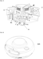
- the invention also relates to a culinary appliance 100 mixer and/or grinder comprising a drive device 1 according to the invention.
- the culinary appliance 100 includes a bowl 101 and a lid 102 designed and configured to close the bowl 101.
- the drive device 1 is contained in the cover 102.
- the culinary appliance 100 may include a food working arm for mixing or grinding.
- a food working arm is positioned in the bowl 101 and connected to the drive member 30 of the drive device 1.
- the training device 1 is integrated into a culinary appliance 100.
- the operation of the training device 1 does not change, whether or not it is integrated into a culinary appliance 100.
- the lever 8 naturally positions (by default) the coupling member 6 in the first coupling position. In this position only unidirectional rotation is permitted.
- This position is preferable for cutting hard foods, such as hazelnuts.
- a user will connect a working arm provided with sharp blades to the drive member 30.
- the rotation of the rotation subassembly 29 is directly transmitted to the coupling member 6 via the face 10a in contact with the face 64
- the first coupling element 10 drives in rotation the coupling member 6, which is integral in rotation with the drive member 30, and the drive member 30 rotates a set of knives (or another culinary tool of a food processing arm).
- the user lets the return spring rewind it.
- the rotation subassembly 29 and the first coupling element 10 then rotate in the opposite direction.
- the ratchet wheel 64 does not allow the transmission of the rotational movement of the first coupling element 10 to the coupling member 6.
- This arrangement is particularly advantageous in the case where the user wishes to chop hard foods because it is preferable that the blades of the working arm rotate only under the action of the pulling of the rope 24 (maximum force) and disengage when the spring 26 rewinds the rope on 10.
- most work arms equipped with blades have only one cutting side.
- the chopped pieces become smaller and smaller, so it may become interesting to increase the rotation speed of the knives.
- the culinary appliance is used to make a mixture or an emulsion, the user will prefer to have a high rotation speed of the tool.
- the user can press the actuator 20. While pressed, the actuator 20 moves the lever 8 in translation. The movement of the lever 8 positions the cutting member 6 in the second coupling position. In this position, the dog wheel 68 of the coupling member 6 is coupled to the second coupling element 12.
- coupling with dogs makes it possible to have a bidirectional rotation transmission.
- the rotation of the rotation subassembly 29 is transmitted to the first coupling element 14a via the side faces 10b, the side faces 14b in turn transmit a rotational movement to the element 12 via the face 12b .
- the face 12a transmits via the face 68 a rotational movement to the part 6.
- the part 6 via the internal grooves finally transmits a rotational movement to the part 30 and therefore to the working arm.
- the claw connection allows that whatever the direction of rotation of the rotation sub-assembly 29 (direction of rotation of traction of the rope or opposite direction of rotation of the rewound by the return spring), this rotational movement will be transmitted to the drive member 30.
- the coupling member 6 when the coupling member 6 is in the second coupling position, whatever the direction of rotation of the rotation sub-assembly 29 and the coupling member 6, the rotation is transmitted to the second coupling element 12.
- the reduction ratio of the connection between the lateral face 10b, the gear 14 and the second coupling element 12 is chosen to favor a high speed (compared to the rotation speed obtained when the coupling member is in the first coupling position).
- This arrangement is particularly advantageous because it avoids potential confusion for the user. He knows that by default, the coupling member 6 is in the first coupling position. In addition, this arrangement helps protect the equipment. Indeed, it is preferable to have a lower rotation speed by default. Otherwise, the equipment could be damaged if a user starts grinding a large piece of meat at high speed. The work arm would not have enough torque to cut the meat.
Landscapes
- Engineering & Computer Science (AREA)
- Chemical & Material Sciences (AREA)
- Chemical Kinetics & Catalysis (AREA)
- Mechanical Engineering (AREA)
- Food Science & Technology (AREA)
- Food-Manufacturing Devices (AREA)
Claims (14)
- Antriebsvorrichtung (1) zum Drehen für ein Küchengerät (100) zum Mischen oder Zerkleinern, wobei die Antriebsvorrichtung (1) umfasst,(i) eine Baugruppe zum Versetzen in Drehung (29),(ii) ein Antriebsbauteil (30) zum Drehen eines Lebensmittelverarbeitungsarms, und(iii) ein Kopplungsbauteil (6) zum Drehen der Baugruppe zum Versetzen in Drehung (29) mit dem Antriebsbauteil (30), um eine Drehbewegung der Baugruppe zum Versetzen in Drehung (29) auf das Antriebsbauteil (30) zu übertragen,wobei die Vorrichtung dadurch gekennzeichnet ist, dass das Kopplungsbauteil (6) zwischen einer ersten Position, in der das Kopplungsbauteil (6) angepasst ist, um eine Bewegung entsprechend einer einzigen Drehrichtung der Baugruppe zum Versetzen in Drehung (29) zu übertragen, und einer zweiten Position beweglich ist, in der das Kopplungsbauteil (6) angepasst ist, eine Bewegung entsprechend zwei Drehrichtungen der Baugruppe zum Versetzen in Drehung (29) zu übertragen.
- Antriebsvorrichtung (1) nach Anspruch 1, wobei das Kopplungsbauteil (6) einen Klinkenradabschnitt (64) umfasst, das erlaubt, eine Bewegung entsprechend einer einzigen Drehrichtung zu übertragen.
- Antriebsvorrichtung (1) nach Anspruch 2, umfassend ein erstes Kupplungselement (10a), dass mit der Baugruppe zum Versetzen in Drehung (29) drehbar verbunden und angepasst ist, um mit dem Klinkenradabschnitt (64) des Kopplungsbauteils (6) gekuppelt zu werden.
- Antriebsvorrichtung (1) nach einem der vorstehenden Ansprüche, wobei das Kopplungsbauteil (6) einen Klauenradabschnitt (68) umfasst, der erlaubt, eine Bewegung entsprechend zwei Drehrichtungen zu übertragen.
- Antriebsvorrichtung (1) nach Anspruch 4, umfassend ein zweites Kupplungselement (12a), dass angepasst ist, um mit dem Klauenradabschnitt (68) des Kopplungsbauteils (6) gekuppelt zu werden, um mit dem Antriebsbauteil (30) drehbar verbunden zu werden.
- Antriebsvorrichtung (1) nach Anspruch 5, umfassend ein Getriebe (14) mit zwei Stufen (14a und 14b), das zwischen dem ersten Kupplungselement (10b) und dem zweiten Kupplungselement (12b) eingefügt ist, um ein Drehmoment und eine Drehgeschwindigkeit einer Bewegung zu modifizieren, das/die von dem ersten Kupplungselement (10b) zu dem zweiten Kupplungselement (12b) übertragen wird, wenn das zweite Kupplungselement (12a) mit dem Klauenradabschnitt (68) des Kopplungsbauteils (6) gekuppelt wird.
- Antriebsvorrichtung (1) nach einem der vorstehenden Ansprüche, wobei das Kopplungsbauteil (6) zwischen der ersten Position und der zweiten Position translationsbeweglich ist.
- Antriebsvorrichtung (1) nach Anspruch 7, umfassend einen Hebel (8), der erlaubt, das Kopplungsbauteil (6) zwischen der ersten Position und der zweiten Position in Translation zu verschieben.
- Antriebsvorrichtung (1) nach Anspruch 8, wobei mindestens ein elastisches Bauteil (16) einen Kraftaufwand auf den Hebel (8) ausübt, um ihn automatisch in die erste Position zu positionieren.
- Antriebsvorrichtung (1) nach einem der Ansprüche 8 oder 9, wobei ein Aktor (20) angepasst ist, um den Hebel (8) in die zweite Position zu positionieren und zu halten.
- Antriebsvorrichtung (1) nach einem der vorstehenden Ansprüche, wobei die Baugruppe zum Versetzen in Drehung (29) einen Aufwickler (10) umfasst, der eine Schnur (24) und eine Rückstellfeder (26) umfasst, wobei der Aufwickler (10) die Baugruppe zum Versetzen in Drehung (29) drehend antreibt.
- Küchengerät (100) zum Mischen oder Zerkleinern, umfassend eine Antriebsvorrichtung (1) nach einem der vorstehenden Ansprüche.
- Küchengerät (100) nach Anspruch 12, umfassend eine Schüssel (101) und einen Deckel (102), der angepasst ist, um die Schüssel (101) zu verschließen, wobei die Antriebsvorrichtung (1) in dem Deckel (102) enthalten ist.
- Küchengerät (100) nach einem der Ansprüche 12 oder 13, umfassend einen herausnehmbaren Lebensmittelverarbeitungsarm zum Mischen oder Zerkleinern, wobei der Lebensmittelverarbeitungsarm an das Antriebsbauteil (30) der Antriebsvorrichtung (1) angeschlossen ist.
Applications Claiming Priority (1)
| Application Number | Priority Date | Filing Date | Title |
|---|---|---|---|
| FR2110039A FR3127108B1 (fr) | 2021-09-23 | 2021-09-23 | Dispositif d’entrainement à rotation unidirectionnelle ou bidirectionnelle |
Publications (2)
| Publication Number | Publication Date |
|---|---|
| EP4154777A1 EP4154777A1 (de) | 2023-03-29 |
| EP4154777B1 true EP4154777B1 (de) | 2024-06-26 |
Family
ID=78086595
Family Applications (1)
| Application Number | Title | Priority Date | Filing Date |
|---|---|---|---|
| EP22195792.1A Active EP4154777B1 (de) | 2021-09-23 | 2022-09-15 | Antriebsvorrichtung mit uni- oder bidirektionaler drehung |
Country Status (6)
| Country | Link |
|---|---|
| US (1) | US20230089788A1 (de) |
| EP (1) | EP4154777B1 (de) |
| JP (1) | JP2023046390A (de) |
| CN (1) | CN115844234B (de) |
| CA (1) | CA3172988A1 (de) |
| FR (1) | FR3127108B1 (de) |
Families Citing this family (3)
| Publication number | Priority date | Publication date | Assignee | Title |
|---|---|---|---|---|
| HK1256212A2 (zh) * | 2018-12-27 | 2019-09-13 | 汪恩光 | 拉动式的换挡传动系统及食物料理机 |
| JP2024135610A (ja) | 2023-03-23 | 2024-10-04 | セイコーエプソン株式会社 | ヘッドユニット、および液体吐出装置 |
| US12527435B2 (en) * | 2023-10-26 | 2026-01-20 | AvoBagel Company Limited | Handheld food cutter |
Family Cites Families (20)
| Publication number | Priority date | Publication date | Assignee | Title |
|---|---|---|---|---|
| DE580073C (de) | 1933-07-05 | Emil Langenscheid | Ruehr- und Schlagmaschine mit stufenlosem Geschwindigkeitswechselgetriebe | |
| DE901641C (de) * | 1949-12-25 | 1954-01-14 | Wilhelm Batz | Auf einen Schuesselrand aufsetzbares Ruehrgeraet |
| US3005232A (en) * | 1951-04-23 | 1961-10-24 | Steinbock | Crucible former and sprue former carrier |
| FR2532540A1 (fr) | 1982-09-08 | 1984-03-09 | Piccini Maurice | Appareil a palette rotative pour faire des sauces |
| US6702455B2 (en) * | 2000-12-01 | 2004-03-09 | Depuy Orthopaedics, Inc. | Bone cement mixing apparatus having improved gearing arrangement for driving a mixing blade |
| EP1449472B2 (de) | 2003-02-19 | 2011-01-19 | Betty Bossi Verlag AG | Handantreibbares Gerät zum Zerkleinern von Lebensmitteln |
| DE202006021005U1 (de) | 2005-04-26 | 2012-01-23 | Leifheit Ag | Reinigungssystem mit einem Wischgerät und einer Vorrichtung zum Trocknen |
| US7681495B2 (en) * | 2005-12-19 | 2010-03-23 | Kwog Kuen So | Food processing device |
| CN101478904B (zh) | 2006-05-04 | 2013-05-15 | 斯维兹普鲁兹股份公司 | 用于处理食品的设备以及用于处理食品设备的工作单元 |
| WO2007128154A1 (de) | 2006-05-04 | 2007-11-15 | Swizzzprozzz Ag | Gerät zum bearbeiten von lebensmitteln |
| US7975948B2 (en) * | 2006-12-21 | 2011-07-12 | Chef'n Corporation | Food processing system |
| US7669793B2 (en) * | 2007-08-17 | 2010-03-02 | Kwok Kuen So | Food cutting device |
| HK1146686A2 (en) * | 2011-03-04 | 2011-06-30 | 汪恩光 | Portable food processor |
| US9004745B1 (en) * | 2012-04-17 | 2015-04-14 | Zoya, Inc. | Mixing apparatus and process |
| US9468340B2 (en) * | 2013-09-16 | 2016-10-18 | Ki Mee Metal & Plastic Factory Limited | Food processing apparatus |
| DE102013112225B4 (de) | 2013-11-06 | 2022-08-25 | Emsa Gmbh | Lebensmittelhäcksler |
| US9925505B2 (en) * | 2014-11-04 | 2018-03-27 | Bishara Tannous | Material handling system and apparatus |
| US11122936B2 (en) * | 2018-01-24 | 2021-09-21 | Progressive International Corporation | Food processor |
| DE202018105480U1 (de) * | 2018-09-24 | 2020-01-02 | Genius Gmbh | Lebensmittelbearbeitungsvorrichtung |
| US20200353428A1 (en) * | 2019-05-09 | 2020-11-12 | Lifetime Brands, Inc. | Emulsification module for use with a food processor |
-
2021
- 2021-09-23 FR FR2110039A patent/FR3127108B1/fr active Active
-
2022
- 2022-09-08 CA CA3172988A patent/CA3172988A1/fr active Pending
- 2022-09-15 EP EP22195792.1A patent/EP4154777B1/de active Active
- 2022-09-20 JP JP2022148876A patent/JP2023046390A/ja active Pending
- 2022-09-22 US US17/950,345 patent/US20230089788A1/en active Pending
- 2022-09-22 CN CN202211157241.8A patent/CN115844234B/zh active Active
Also Published As
| Publication number | Publication date |
|---|---|
| CN115844234B (zh) | 2025-10-14 |
| EP4154777A1 (de) | 2023-03-29 |
| CA3172988A1 (fr) | 2023-03-23 |
| FR3127108A1 (fr) | 2023-03-24 |
| US20230089788A1 (en) | 2023-03-23 |
| FR3127108B1 (fr) | 2023-09-15 |
| CN115844234A (zh) | 2023-03-28 |
| JP2023046390A (ja) | 2023-04-04 |
Similar Documents
| Publication | Publication Date | Title |
|---|---|---|
| EP4154777A1 (de) | Antriebsvorrichtung mit uni- oder bidirektionaler drehung | |
| WO2018002477A1 (fr) | Transmission, notamment pour engin roulant, et engin roulant équipe d'une telle transmission | |
| EP2454930B1 (de) | Übertragungsvorrichtung für einen Automotor, und mit einer solchen Übertragungsvorrichtung ausgestatteter Automotor | |
| EP2989341A1 (de) | Getriebe für ein radfahrzeug mit einem mitnehmerantrieb sowie radfahrzeug mit solch einem getriebe | |
| FR2824376A1 (fr) | Transmission de vitesse pour tondeuse a gazon automotrice et tondeuse equipee d'une telle transmission | |
| EP2627600B1 (de) | Spill mit vorrichtung zur beurteilung der spannung eines darum gewickelten seils und vorrichtung zur automatischen auswahl von mindestens einer geschwindigkeit je nach dieser spannung | |
| FR2576072A1 (fr) | Ensemble d'embrayage reversible pour la marine | |
| FR2549553A1 (fr) | Embrayage pour vehicule de travail tel que motoculteur | |
| WO2014106714A1 (fr) | Boîte de vitesses pour engin automoteur, tel que tondeuse à gazon | |
| EP2627928B1 (de) | Getriebe für eine motorisierte landwirtschaftliche vorrichtung und motorisierte landwirtschaftliche vorrichtung mit einem derartigen getriebe | |
| EP4205907B1 (de) | Schraubgerät mit zwei geschwindigkeiten mit gangwechsel durch beschleunigungskontrolle | |
| EP0643239B1 (de) | Getriebe mit eingebauter Kupplung | |
| FR2533985A1 (fr) | Outil portatif a transmission mecanique souple | |
| FR2946405A1 (fr) | Dispositif d'inversion de sens de marche d'un engin roulant automoteur | |
| FR2917797A1 (fr) | Transmission entre un organe moteur et des roues et engin comportant une telle transmission | |
| FR2709795A1 (fr) | Dispositif d'entraînement non permanent pour mécanisme réducteur de transmission. | |
| FR2485128A1 (fr) | Embrayage et dispositif de condamnation electrique centralisee des serrures d'un vehicule automobile mettant en oeuvre ledit embrayage | |
| FR3096421A1 (fr) | Boîtier de transmission et engin automoteur roulant équipé d'un tel boîtier | |
| EP4552801A1 (de) | Vorrichtung zum anziehen und lösen mit zwei geschwindigkeiten und einem beweglichen hohlrad | |
| FR2770741A1 (fr) | Machine agricole comportant une boite de vitesses pour entrainer un organe fonctionnel | |
| BE524214A (de) | ||
| BE422114A (de) | ||
| BE534360A (de) | ||
| BE476834A (de) | ||
| FR2861911A1 (fr) | Dispositif motorise pour l'entrainement en rotation d'une piece mecanique |
Legal Events
| Date | Code | Title | Description |
|---|---|---|---|
| PUAI | Public reference made under article 153(3) epc to a published international application that has entered the european phase |
Free format text: ORIGINAL CODE: 0009012 |
|
| STAA | Information on the status of an ep patent application or granted ep patent |
Free format text: STATUS: THE APPLICATION HAS BEEN PUBLISHED |
|
| AK | Designated contracting states |
Kind code of ref document: A1 Designated state(s): AL AT BE BG CH CY CZ DE DK EE ES FI FR GB GR HR HU IE IS IT LI LT LU LV MC MK MT NL NO PL PT RO RS SE SI SK SM TR |
|
| STAA | Information on the status of an ep patent application or granted ep patent |
Free format text: STATUS: REQUEST FOR EXAMINATION WAS MADE |
|
| 17P | Request for examination filed |
Effective date: 20230925 |
|
| RBV | Designated contracting states (corrected) |
Designated state(s): AL AT BE BG CH CY CZ DE DK EE ES FI FR GB GR HR HU IE IS IT LI LT LU LV MC MK MT NL NO PL PT RO RS SE SI SK SM TR |
|
| GRAP | Despatch of communication of intention to grant a patent |
Free format text: ORIGINAL CODE: EPIDOSNIGR1 |
|
| RIC1 | Information provided on ipc code assigned before grant |
Ipc: A47J 43/10 20060101ALI20240213BHEP Ipc: A47J 43/08 20060101AFI20240213BHEP |
|
| STAA | Information on the status of an ep patent application or granted ep patent |
Free format text: STATUS: GRANT OF PATENT IS INTENDED |
|
| INTG | Intention to grant announced |
Effective date: 20240321 |
|
| RIN1 | Information on inventor provided before grant (corrected) |
Inventor name: PLICHON, STEPHANE Inventor name: BENOIT, DAVID |
|
| GRAS | Grant fee paid |
Free format text: ORIGINAL CODE: EPIDOSNIGR3 |
|
| GRAA | (expected) grant |
Free format text: ORIGINAL CODE: 0009210 |
|
| STAA | Information on the status of an ep patent application or granted ep patent |
Free format text: STATUS: THE PATENT HAS BEEN GRANTED |
|
| AK | Designated contracting states |
Kind code of ref document: B1 Designated state(s): AL AT BE BG CH CY CZ DE DK EE ES FI FR GB GR HR HU IE IS IT LI LT LU LV MC MK MT NL NO PL PT RO RS SE SI SK SM TR |
|
| REG | Reference to a national code |
Ref country code: GB Ref legal event code: FG4D Free format text: NOT ENGLISH |
|
| REG | Reference to a national code |
Ref country code: CH Ref legal event code: EP |
|
| REG | Reference to a national code |
Ref country code: DE Ref legal event code: R096 Ref document number: 602022004139 Country of ref document: DE |
|
| PG25 | Lapsed in a contracting state [announced via postgrant information from national office to epo] |
Ref country code: BG Free format text: LAPSE BECAUSE OF FAILURE TO SUBMIT A TRANSLATION OF THE DESCRIPTION OR TO PAY THE FEE WITHIN THE PRESCRIBED TIME-LIMIT Effective date: 20240626 |
|
| PG25 | Lapsed in a contracting state [announced via postgrant information from national office to epo] |
Ref country code: FI Free format text: LAPSE BECAUSE OF FAILURE TO SUBMIT A TRANSLATION OF THE DESCRIPTION OR TO PAY THE FEE WITHIN THE PRESCRIBED TIME-LIMIT Effective date: 20240626 Ref country code: HR Free format text: LAPSE BECAUSE OF FAILURE TO SUBMIT A TRANSLATION OF THE DESCRIPTION OR TO PAY THE FEE WITHIN THE PRESCRIBED TIME-LIMIT Effective date: 20240626 |
|
| REG | Reference to a national code |
Ref country code: LT Ref legal event code: MG9D |
|
| PG25 | Lapsed in a contracting state [announced via postgrant information from national office to epo] |
Ref country code: GR Free format text: LAPSE BECAUSE OF FAILURE TO SUBMIT A TRANSLATION OF THE DESCRIPTION OR TO PAY THE FEE WITHIN THE PRESCRIBED TIME-LIMIT Effective date: 20240927 |
|
| PG25 | Lapsed in a contracting state [announced via postgrant information from national office to epo] |
Ref country code: LV Free format text: LAPSE BECAUSE OF FAILURE TO SUBMIT A TRANSLATION OF THE DESCRIPTION OR TO PAY THE FEE WITHIN THE PRESCRIBED TIME-LIMIT Effective date: 20240626 |
|
| REG | Reference to a national code |
Ref country code: NL Ref legal event code: MP Effective date: 20240626 |
|
| PG25 | Lapsed in a contracting state [announced via postgrant information from national office to epo] |
Ref country code: NO Free format text: LAPSE BECAUSE OF FAILURE TO SUBMIT A TRANSLATION OF THE DESCRIPTION OR TO PAY THE FEE WITHIN THE PRESCRIBED TIME-LIMIT Effective date: 20240926 Ref country code: LV Free format text: LAPSE BECAUSE OF FAILURE TO SUBMIT A TRANSLATION OF THE DESCRIPTION OR TO PAY THE FEE WITHIN THE PRESCRIBED TIME-LIMIT Effective date: 20240626 Ref country code: HR Free format text: LAPSE BECAUSE OF FAILURE TO SUBMIT A TRANSLATION OF THE DESCRIPTION OR TO PAY THE FEE WITHIN THE PRESCRIBED TIME-LIMIT Effective date: 20240626 Ref country code: GR Free format text: LAPSE BECAUSE OF FAILURE TO SUBMIT A TRANSLATION OF THE DESCRIPTION OR TO PAY THE FEE WITHIN THE PRESCRIBED TIME-LIMIT Effective date: 20240927 Ref country code: FI Free format text: LAPSE BECAUSE OF FAILURE TO SUBMIT A TRANSLATION OF THE DESCRIPTION OR TO PAY THE FEE WITHIN THE PRESCRIBED TIME-LIMIT Effective date: 20240626 Ref country code: BG Free format text: LAPSE BECAUSE OF FAILURE TO SUBMIT A TRANSLATION OF THE DESCRIPTION OR TO PAY THE FEE WITHIN THE PRESCRIBED TIME-LIMIT Effective date: 20240626 Ref country code: RS Free format text: LAPSE BECAUSE OF FAILURE TO SUBMIT A TRANSLATION OF THE DESCRIPTION OR TO PAY THE FEE WITHIN THE PRESCRIBED TIME-LIMIT Effective date: 20240926 |
|
| PG25 | Lapsed in a contracting state [announced via postgrant information from national office to epo] |
Ref country code: NL Free format text: LAPSE BECAUSE OF FAILURE TO SUBMIT A TRANSLATION OF THE DESCRIPTION OR TO PAY THE FEE WITHIN THE PRESCRIBED TIME-LIMIT Effective date: 20240626 |
|
| REG | Reference to a national code |
Ref country code: AT Ref legal event code: MK05 Ref document number: 1696956 Country of ref document: AT Kind code of ref document: T Effective date: 20240626 |
|
| PG25 | Lapsed in a contracting state [announced via postgrant information from national office to epo] |
Ref country code: NL Free format text: LAPSE BECAUSE OF FAILURE TO SUBMIT A TRANSLATION OF THE DESCRIPTION OR TO PAY THE FEE WITHIN THE PRESCRIBED TIME-LIMIT Effective date: 20240626 |
|
| PG25 | Lapsed in a contracting state [announced via postgrant information from national office to epo] |
Ref country code: PT Free format text: LAPSE BECAUSE OF FAILURE TO SUBMIT A TRANSLATION OF THE DESCRIPTION OR TO PAY THE FEE WITHIN THE PRESCRIBED TIME-LIMIT Effective date: 20241028 |
|
| PG25 | Lapsed in a contracting state [announced via postgrant information from national office to epo] |
Ref country code: PT Free format text: LAPSE BECAUSE OF FAILURE TO SUBMIT A TRANSLATION OF THE DESCRIPTION OR TO PAY THE FEE WITHIN THE PRESCRIBED TIME-LIMIT Effective date: 20241028 |
|
| PG25 | Lapsed in a contracting state [announced via postgrant information from national office to epo] |
Ref country code: PL Free format text: LAPSE BECAUSE OF FAILURE TO SUBMIT A TRANSLATION OF THE DESCRIPTION OR TO PAY THE FEE WITHIN THE PRESCRIBED TIME-LIMIT Effective date: 20240626 |
|
| PG25 | Lapsed in a contracting state [announced via postgrant information from national office to epo] |
Ref country code: EE Free format text: LAPSE BECAUSE OF FAILURE TO SUBMIT A TRANSLATION OF THE DESCRIPTION OR TO PAY THE FEE WITHIN THE PRESCRIBED TIME-LIMIT Effective date: 20240626 |
|
| PG25 | Lapsed in a contracting state [announced via postgrant information from national office to epo] |
Ref country code: AT Free format text: LAPSE BECAUSE OF FAILURE TO SUBMIT A TRANSLATION OF THE DESCRIPTION OR TO PAY THE FEE WITHIN THE PRESCRIBED TIME-LIMIT Effective date: 20240626 Ref country code: IS Free format text: LAPSE BECAUSE OF FAILURE TO SUBMIT A TRANSLATION OF THE DESCRIPTION OR TO PAY THE FEE WITHIN THE PRESCRIBED TIME-LIMIT Effective date: 20241026 |
|
| PG25 | Lapsed in a contracting state [announced via postgrant information from national office to epo] |
Ref country code: CZ Free format text: LAPSE BECAUSE OF FAILURE TO SUBMIT A TRANSLATION OF THE DESCRIPTION OR TO PAY THE FEE WITHIN THE PRESCRIBED TIME-LIMIT Effective date: 20240626 |
|
| PG25 | Lapsed in a contracting state [announced via postgrant information from national office to epo] |
Ref country code: RO Free format text: LAPSE BECAUSE OF FAILURE TO SUBMIT A TRANSLATION OF THE DESCRIPTION OR TO PAY THE FEE WITHIN THE PRESCRIBED TIME-LIMIT Effective date: 20240626 Ref country code: SK Free format text: LAPSE BECAUSE OF FAILURE TO SUBMIT A TRANSLATION OF THE DESCRIPTION OR TO PAY THE FEE WITHIN THE PRESCRIBED TIME-LIMIT Effective date: 20240626 |
|
| PG25 | Lapsed in a contracting state [announced via postgrant information from national office to epo] |
Ref country code: ES Free format text: LAPSE BECAUSE OF FAILURE TO SUBMIT A TRANSLATION OF THE DESCRIPTION OR TO PAY THE FEE WITHIN THE PRESCRIBED TIME-LIMIT Effective date: 20240626 Ref country code: SM Free format text: LAPSE BECAUSE OF FAILURE TO SUBMIT A TRANSLATION OF THE DESCRIPTION OR TO PAY THE FEE WITHIN THE PRESCRIBED TIME-LIMIT Effective date: 20240626 |
|
| PG25 | Lapsed in a contracting state [announced via postgrant information from national office to epo] |
Ref country code: SM Free format text: LAPSE BECAUSE OF FAILURE TO SUBMIT A TRANSLATION OF THE DESCRIPTION OR TO PAY THE FEE WITHIN THE PRESCRIBED TIME-LIMIT Effective date: 20240626 Ref country code: SK Free format text: LAPSE BECAUSE OF FAILURE TO SUBMIT A TRANSLATION OF THE DESCRIPTION OR TO PAY THE FEE WITHIN THE PRESCRIBED TIME-LIMIT Effective date: 20240626 Ref country code: RO Free format text: LAPSE BECAUSE OF FAILURE TO SUBMIT A TRANSLATION OF THE DESCRIPTION OR TO PAY THE FEE WITHIN THE PRESCRIBED TIME-LIMIT Effective date: 20240626 Ref country code: PL Free format text: LAPSE BECAUSE OF FAILURE TO SUBMIT A TRANSLATION OF THE DESCRIPTION OR TO PAY THE FEE WITHIN THE PRESCRIBED TIME-LIMIT Effective date: 20240626 Ref country code: IS Free format text: LAPSE BECAUSE OF FAILURE TO SUBMIT A TRANSLATION OF THE DESCRIPTION OR TO PAY THE FEE WITHIN THE PRESCRIBED TIME-LIMIT Effective date: 20241026 Ref country code: ES Free format text: LAPSE BECAUSE OF FAILURE TO SUBMIT A TRANSLATION OF THE DESCRIPTION OR TO PAY THE FEE WITHIN THE PRESCRIBED TIME-LIMIT Effective date: 20240626 Ref country code: EE Free format text: LAPSE BECAUSE OF FAILURE TO SUBMIT A TRANSLATION OF THE DESCRIPTION OR TO PAY THE FEE WITHIN THE PRESCRIBED TIME-LIMIT Effective date: 20240626 Ref country code: CZ Free format text: LAPSE BECAUSE OF FAILURE TO SUBMIT A TRANSLATION OF THE DESCRIPTION OR TO PAY THE FEE WITHIN THE PRESCRIBED TIME-LIMIT Effective date: 20240626 Ref country code: AT Free format text: LAPSE BECAUSE OF FAILURE TO SUBMIT A TRANSLATION OF THE DESCRIPTION OR TO PAY THE FEE WITHIN THE PRESCRIBED TIME-LIMIT Effective date: 20240626 |
|
| PG25 | Lapsed in a contracting state [announced via postgrant information from national office to epo] |
Ref country code: IT Free format text: LAPSE BECAUSE OF FAILURE TO SUBMIT A TRANSLATION OF THE DESCRIPTION OR TO PAY THE FEE WITHIN THE PRESCRIBED TIME-LIMIT Effective date: 20240626 |
|
| REG | Reference to a national code |
Ref country code: DE Ref legal event code: R097 Ref document number: 602022004139 Country of ref document: DE |
|
| PG25 | Lapsed in a contracting state [announced via postgrant information from national office to epo] |
Ref country code: DK Free format text: LAPSE BECAUSE OF FAILURE TO SUBMIT A TRANSLATION OF THE DESCRIPTION OR TO PAY THE FEE WITHIN THE PRESCRIBED TIME-LIMIT Effective date: 20240626 |
|
| PG25 | Lapsed in a contracting state [announced via postgrant information from national office to epo] |
Ref country code: MC Free format text: LAPSE BECAUSE OF FAILURE TO SUBMIT A TRANSLATION OF THE DESCRIPTION OR TO PAY THE FEE WITHIN THE PRESCRIBED TIME-LIMIT Effective date: 20240626 |
|
| PLBE | No opposition filed within time limit |
Free format text: ORIGINAL CODE: 0009261 |
|
| STAA | Information on the status of an ep patent application or granted ep patent |
Free format text: STATUS: NO OPPOSITION FILED WITHIN TIME LIMIT |
|
| PG25 | Lapsed in a contracting state [announced via postgrant information from national office to epo] |
Ref country code: LU Free format text: LAPSE BECAUSE OF NON-PAYMENT OF DUE FEES Effective date: 20240915 |
|
| 26N | No opposition filed |
Effective date: 20250327 |
|
| REG | Reference to a national code |
Ref country code: BE Ref legal event code: MM Effective date: 20240930 |
|
| PG25 | Lapsed in a contracting state [announced via postgrant information from national office to epo] |
Ref country code: BE Free format text: LAPSE BECAUSE OF NON-PAYMENT OF DUE FEES Effective date: 20240930 |
|
| PG25 | Lapsed in a contracting state [announced via postgrant information from national office to epo] |
Ref country code: IE Free format text: LAPSE BECAUSE OF NON-PAYMENT OF DUE FEES Effective date: 20240915 |
|
| PG25 | Lapsed in a contracting state [announced via postgrant information from national office to epo] |
Ref country code: SE Free format text: LAPSE BECAUSE OF FAILURE TO SUBMIT A TRANSLATION OF THE DESCRIPTION OR TO PAY THE FEE WITHIN THE PRESCRIBED TIME-LIMIT Effective date: 20240626 |
|
| REG | Reference to a national code |
Ref country code: CH Ref legal event code: U11 Free format text: ST27 STATUS EVENT CODE: U-0-0-U10-U11 (AS PROVIDED BY THE NATIONAL OFFICE) Effective date: 20251001 |
|
| PGFP | Annual fee paid to national office [announced via postgrant information from national office to epo] |
Ref country code: DE Payment date: 20250916 Year of fee payment: 4 |
|
| PGFP | Annual fee paid to national office [announced via postgrant information from national office to epo] |
Ref country code: FR Payment date: 20250929 Year of fee payment: 4 |
|
| PGFP | Annual fee paid to national office [announced via postgrant information from national office to epo] |
Ref country code: CH Payment date: 20251001 Year of fee payment: 4 |
|
| PG25 | Lapsed in a contracting state [announced via postgrant information from national office to epo] |
Ref country code: CY Free format text: LAPSE BECAUSE OF FAILURE TO SUBMIT A TRANSLATION OF THE DESCRIPTION OR TO PAY THE FEE WITHIN THE PRESCRIBED TIME-LIMIT; INVALID AB INITIO Effective date: 20220915 |
|
| PG25 | Lapsed in a contracting state [announced via postgrant information from national office to epo] |
Ref country code: HU Free format text: LAPSE BECAUSE OF FAILURE TO SUBMIT A TRANSLATION OF THE DESCRIPTION OR TO PAY THE FEE WITHIN THE PRESCRIBED TIME-LIMIT; INVALID AB INITIO Effective date: 20220915 |