EP4552801A1 - Vorrichtung zum anziehen und lösen mit zwei geschwindigkeiten und einem beweglichen hohlrad - Google Patents
Vorrichtung zum anziehen und lösen mit zwei geschwindigkeiten und einem beweglichen hohlrad Download PDFInfo
- Publication number
- EP4552801A1 EP4552801A1 EP24211256.3A EP24211256A EP4552801A1 EP 4552801 A1 EP4552801 A1 EP 4552801A1 EP 24211256 A EP24211256 A EP 24211256A EP 4552801 A1 EP4552801 A1 EP 4552801A1
- Authority
- EP
- European Patent Office
- Prior art keywords
- crown
- rotor
- gear train
- locking member
- additional gear
- Prior art date
- Legal status (The legal status is an assumption and is not a legal conclusion. Google has not performed a legal analysis and makes no representation as to the accuracy of the status listed.)
- Withdrawn
Links
Images


Classifications
-
- B—PERFORMING OPERATIONS; TRANSPORTING
- B25—HAND TOOLS; PORTABLE POWER-DRIVEN TOOLS; MANIPULATORS
- B25B—TOOLS OR BENCH DEVICES NOT OTHERWISE PROVIDED FOR, FOR FASTENING, CONNECTING, DISENGAGING OR HOLDING
- B25B21/00—Portable power-driven screw or nut setting or loosening tools; Attachments for drilling apparatus serving the same purpose
- B25B21/008—Portable power-driven screw or nut setting or loosening tools; Attachments for drilling apparatus serving the same purpose with automatic change-over from high speed-low torque mode to low speed-high torque mode
-
- B—PERFORMING OPERATIONS; TRANSPORTING
- B25—HAND TOOLS; PORTABLE POWER-DRIVEN TOOLS; MANIPULATORS
- B25B—TOOLS OR BENCH DEVICES NOT OTHERWISE PROVIDED FOR, FOR FASTENING, CONNECTING, DISENGAGING OR HOLDING
- B25B23/00—Details of, or accessories for, spanners, wrenches, screwdrivers
- B25B23/14—Arrangement of torque limiters or torque indicators in wrenches or screwdrivers
- B25B23/141—Mechanical overload release couplings
-
- B—PERFORMING OPERATIONS; TRANSPORTING
- B25—HAND TOOLS; PORTABLE POWER-DRIVEN TOOLS; MANIPULATORS
- B25B—TOOLS OR BENCH DEVICES NOT OTHERWISE PROVIDED FOR, FOR FASTENING, CONNECTING, DISENGAGING OR HOLDING
- B25B23/00—Details of, or accessories for, spanners, wrenches, screwdrivers
- B25B23/14—Arrangement of torque limiters or torque indicators in wrenches or screwdrivers
- B25B23/147—Arrangement of torque limiters or torque indicators in wrenches or screwdrivers specially adapted for electrically operated wrenches or screwdrivers
-
- B—PERFORMING OPERATIONS; TRANSPORTING
- B25—HAND TOOLS; PORTABLE POWER-DRIVEN TOOLS; MANIPULATORS
- B25F—COMBINATION OR MULTI-PURPOSE TOOLS NOT OTHERWISE PROVIDED FOR; DETAILS OR COMPONENTS OF PORTABLE POWER-DRIVEN TOOLS NOT PARTICULARLY RELATED TO THE OPERATIONS PERFORMED AND NOT OTHERWISE PROVIDED FOR
- B25F5/00—Details or components of portable power-driven tools not particularly related to the operations performed and not otherwise provided for
- B25F5/001—Gearings, speed selectors, clutches or the like specially adapted for rotary tools
Definitions
- the field of the invention is that of the design and manufacture of portable tools intended to be used to carry out screwing/unscrewing operations.
- the invention relates to a screwing/unscrewing device offering several screwing/unscrewing speeds.
- This device is more particularly intended for continuous tightening screwdrivers whose torque exceeds 150 N.m (high torque screwdrivers).
- Screwdriving devices are commonly used in various industrial sectors to carry out screwdriving and/or unscrewing operations on assemblies.
- Electric motor-driven screwdriving devices are typically associated with control means and include a tightening torque and/or tightening angle sensor.
- control means make it possible to program screwing strategies, i.e. the parameters of the pre-screwing and tightening phases, in particular the rotation speeds of the motor in the pre-screwing and tightening phases, as well as the target torque and/or angle value at the end of tightening.
- the control means control the motor to drive the element to be tightened at the pre-screwing speed during the pre-screwing phase and then at the tightening speed during the tightening phase until the target torque and/or angle are reached.
- Continuous tightening screwdrivers i.e. screwdrivers which apply an uninterrupted and increasing torque to the screw during tightening, incorporate a transmission between the motor and the output device driving the screw.
- This transmission generally consists of one or more epicyclic gear trains. These epicyclic gear trains allow for a torque sufficient available tightening torque on the output shaft. This torque is the result of multiplying the engine torque by the transmission reduction ratio and its efficiency.
- screwdriver manufacturers are therefore required to have a high reduction ratio by having several epicyclic gear trains in the transmission. This has the disadvantage that the rotation frequency of the screwdriver output shaft becomes relatively low, resulting in a long screwing time, which penalizes productivity.
- the pre-screwing and tightening speeds applied during the pre-screwing and tightening phases therefore require the implementation of an additional engageable-disengageable gear train which makes it possible to define different reduction ratios between the rotor and the output member depending on whether it is engaged or not.
- the additional gear train is not engaged in the pre-tightening phase so that the pre-screwing speed is fast.
- the additional train is engaged during the tightening phase so that the tightening speed is slower and the tightening torque achievable by the screwing device is higher.
- the additional gear train is automatically mechanically engaged at the end of the pre-tightening phase.
- the transmission incorporates an elastic element which allows, when the tightening torque reaches, during the pre-tightening phase, a predetermined torque threshold for gear change, to automatically engage the additional gear train.
- This type of mechanism is advantageous in that it allows for simple and efficient automatic screw speed changes. However, this type of technology can still be improved.
- the predetermined torque threshold for changing gear from which the additional train engages automatically is not configurable since it depends on the sizing of the elastic element integrated into the transmission. Therefore, this type of technology does not allow for the provision of versatile screwdrivers adaptable to different screwing operations requiring a change of speed after reaching a pre-tightening threshold of different values.
- the Applicant has designed a technique enabling the instant at which the additional train is triggered to be chosen so as to adapt this engagement according to the needs of the screwing operation to be carried out.
- the invention aims in particular to provide an effective solution to at least some of these different problems.
- an objective of the invention is to improve the screwing devices making it possible to ensure the engagement-disengagement of an additional gear train.
- the invention aims, according to at least one embodiment, to provide such a screwing device in which the engagement of an additional train is done independently of the tightening torque and as a function of the acceleration of the motor.
- Another objective of the invention is, according to at least one embodiment, to provide such a screwing device which is simplified.
- an objective of the invention is, according to at least one embodiment, to simplify the manner in which the crown of the additional epicyclic gear train can be locked-unlocked in rotation relative to the casing of the screwing device to engage-disengage the additional gear train could be simplified.
- Another objective of the invention is, in at least one embodiment, to reduce the number of components used.
- Another objective of the invention is, according to at least one embodiment, to provide a solution that can be easily integrated into various screwing/unscrewing devices.
- Another objective of the invention is, according to at least one embodiment, to provide a solution which is reliable and/or robust and/or economical.
- the invention proposes a screwing and/or unscrewing device making it possible to ensure the engagement-disengagement of an additional gear train, in particular a simple one, having a reduced number of parts, the engagement-disengagement mechanism of which is easily integrated into the tool.
- a screwing device comprises means for controlling said motor, said means for controlling said motor being configured to generate a predetermined acceleration or deceleration of said rotor, said predetermined acceleration or deceleration acting on said engagement means to make them pass from one of their states to the other.
- the invention thus provides a screwing device in which the engagement of an additional train is done independently of the tightening torque and as a function of the acceleration of the motor.
- said internal toothed crown comprises a first locking portion and said casing comprises a second locking portion, said first and second locking portions being complementary to one another and shaped to ensure rotational locking of said crown relative to said casing when they cooperate with each other, said first and second locking portions cooperating with each other in said locked position of said crown and not cooperating with each other in said free position of said crown.
- said first and second blocking portions are of truncated cone shape.
- a screwing device comprises elastic return means acting on said crown to tend to keep it in said blocked position.
- said engagement means comprise means for driving said crown in translation from one to the other of its locked and unlocked positions, said drive means being configured to transform a rotation of said rotor into a translation of said crown following the generation of said predetermined acceleration/deceleration by said control means of said motor.
- a screwing device comprises means for connecting in rotation said crown and said rotor, said means for connecting in rotation comprising said at least one locking member and at least one element forming a stop secured to said crown, said element forming a stop being arranged in such a way that said locking member bears against said element forming a stop when said locking member is in said active position and in said first extreme position.
- said cam path comprises a conformation capable of at least partially housing said locking member when it is in its first extreme position, said conformation being configured to reversibly maintain said locking member in said first extreme position.
- said selection member comprises a cam surface in contact with said locking member, said cam surface acting on said locking member to enable its movement from one of its active and inactive positions to the other.
- said locking member is held in abutment against said cam surface by an elastic return means, said elastic return means acting on said locking member to tend to move it towards its active position.
- said locking member is movable in translation between its active and inactive positions along an axis orthogonal to the axis of rotation of said rotor.
- a screwing device comprises a support element linked in rotation to said rotor, said at least one member of locking being integral in rotation with said support element and mounted to move relative to the latter between its active and inactive positions, said selection member being mounted to move relative to said support element between its engagement and disengagement positions, said support element comprising stop elements against which stop elements of said selection member are capable of coming to bear, said stop elements defining said engagement and disengagement positions of said selection member.
- Such a screwing device can be used to carry out screwing and/or unscrewing operations.
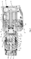
- such a screwing and/or unscrewing device conventionally comprises a casing 10.
- This is a pistol-grip type casing in which the axis of the handle 11 forms an angle with the axis of the output member 12.
- it could be a casing in which the axis of the handle coincides with the axis of the output member.
- the casing 10 houses an electric motor 13 comprising a stator 130 and a rotor 131 provided with a motor shaft 132.
- the rotor is external. In variants, it could be internal.
- the device comprises an output member 12 placed at the end of the casing 10.
- This output member 12 is capable of driving in rotation a drive element of an element to be screwed, in particular a screw socket or other.
- the device comprises a transmission T connecting the shaft 132 of the rotor 131 to the output member 12 so as to drive the latter in rotation.
- the transmission T comprises a two-speed mechanism 14 which comprises two transmission chains having different transmission ratios.
- the transmission T comprises an additional gear train capable of being engaged/disengaged.
- this additional train here comprises an epicyclic train which can be disengaged by making its inner toothed crown free to rotate or engaged by locking its crown in rotation.
- the reduction ratio of the transmission between the rotor and the output member is different depending on whether the additional gear train is engaged or not, the reduction ratio being higher here when the additional gear train is engaged.
- the reduction ratio may be higher when the additional gear train is engaged. In this way, for a given rotation frequency of the rotor, the rotation frequency of the output member is higher when the additional gear train is not engaged and slower when it is engaged so that the torque of The tightening force that can be delivered by the device is higher when the additional gear train is engaged.
- the engagement means comprise a support element 15.
- This support element 15 is mounted to rotate in the casing 10 along the axis of the rotor 131. At one of its ends, it is secured to the motor shaft 132 in such a way that it is linked in rotation to the rotor 131.
- the assembly of the support element 15 and the motor shaft 132 can for this purpose be achieved by means of splines 151. At the other of its ends, it comprises a sun gear 152.
- the motor shaft 132 and the support element 15 could in a variant constitute a single piece.
- the selection member 16 is rotationally connected to the support element 15 by rotational connection means.
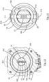
- the support element 15 is traversed by a transverse bore 153 arranged along an axis perpendicular to its longitudinal axis.
- This bore 153 houses an elastic return means which comprises in this embodiment a compression spring 17.
- a locking element At each end of the compression spring 17 is placed a locking element.
- the selection member 16 is crossed by an internal bore 160 housing the support element 15. Two pairs of diametrically opposed locking housings 162 are provided on the periphery of the internal bore 160. The locking housings 162 of each pair are connected by a peripheral groove 163.
- the locking balls 18 are housed in two of the first of the opposite housings 162.
- the balls 18 are located in two other of the opposite housings 162.
- the means for rotationally connecting the support element 15 to the selection member 16 are able to transmit a predetermined limit torque CI beyond which the balls pass into their release position in which the support element and the selection member are no longer rotationally connected and can no longer transmit torque.
- This predetermined torque depends in particular on the stiffness of the spring 17, the size of the balls 18, the geometry of the locking housings 162 and the groove 163. This torque can be conventionally determined by calculation or empirically.
- the device conventionally comprises means for measuring the tightening torque delivered by the device at the output member.
- These measuring means may, for example, comprise a torque sensor placed in the transmission between the rotor and the output member or a current sensor consumed by the motor.
- the device conventionally comprises means 19 for controlling the motor. These means make it possible to control the motor, in particular by controlling its electrical power supply. They may be totally or partially located inside the casing or outside it.
- the control means 19 of the motor make it possible, by acting on the acceleration/deceleration of the rotor 131 of the motor 13, to switch the engagement means from one of their states to the other, i.e. to switch the selection member 16 from one of its positions to the other relative to the support element 15.
- the acceleration/deceleration generated by the motor must be greater than the quotient of the limit torque CI transmissible by the rotating connection means by the inertia Jos of the selection member along its axis of rotation.
- This acceleration/deceleration is called speed change acceleration/deceleration to the extent that it enables to engage/disengage the additional gear train and thus modify the reduction ratio of the transmission between the rotor and the output member.
- the motor typically produces accelerations and variations in acceleration, particularly at start-up. It is therefore appropriate that the acceleration/deceleration which induces the switching of the engagement means from one state to the other be sufficiently discriminating, i.e. far removed from and more precisely greater than the accelerations which are typically likely to occur, for example at start-up or stop-up, so as not to cause untimely involuntary switching of the selection means from one state to the other.
- the transmission comprises an epicyclic gear train comprising the sun gear 152 rotationally fixed to the support element 15, a planet carrier 20 rotationally fixed to the output member 12, and an internal toothed crown 21 meshing with planet gears 22 carried by the planet carrier 20.
- the planet carrier may be rotationally linked to the input of another epicyclic gear train or a cascade of epicyclic gear trains, the output of which will be rotationally linked to the output member 12.
- the crown 21 is mounted to rotate inside the casing by means of a bearing 23.
- the crown 21 has, at one of its ends, a locking portion 210 of truncated cone shape.
- the casing 10 has a truncated conical locking portion 100.
- the locking portions 210 and 100 are complementary in shape and intended to cooperate with each other.
- a compression spring 24 is interposed between a bearing surface 250 of a base 25 in which the crown 21 is mounted to move in translation between its two extreme positions. This compression spring 24 acts on the crown 21 to tend to keep it in its locked position.
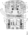
- the crown 21 has, at one of its ends, two pairs of cam tracks 211.
- Each cam track 211 has an inclined surface thickening from a hollow 212 towards the end of the crown 21 oriented towards the support element 15.
- a stop element 213 is provided at the thickest end of each cam track 211.
- the connection zone between each cam track 211 and each stop element 213 comprises a conformation 214.
- the support element 15 is crossed by a transverse bore 154.
- This bore 154 houses two locking members 26 mounted to slide in the bore 154 and in a diametrically opposite manner.
- a compression spring 27 is interposed in the bore 154 between the two locking members 26 and tends to move them away from each other.
- Each locking member 26 comprises a guide housing 261 arranged laterally.
- the selection member 16 has, at its end oriented towards the locking members 26, cam surfaces 164 shaped to interact with the guide housings 261 of the locking members 26 by being housed therein. These cam surfaces 164 have a thin end from which it tends to extend radially to a thicker end.
- cam surfaces are capable of acting on the locking members to release their movement from their inactive position to their active position and to induce their movement from their active position to their inactive position.
- the locking members are held in abutment against the cam surfaces by the spring 27, this spring 27 acting on the locking members to tend to move them towards their active position.
- the selection member 16 comprises diametrically opposed stop elements 165 intended to bear against stop elements 155 provided for this purpose on the support element 15. These stops 165, 155 define the engagement and disengagement positions of the selection member 16. As will become more clear from reading the description of the operation of a device according to the invention, these stops make it possible to stop the rotation of the selection member 16 relative to the support element 15 without passing through the locking members 26. This makes it possible to protect the locking members from impacts when the selection member 16 is in rotation. selection 16 reaches its on and off positions.
- the stop-forming elements 213 of the crown 21 are arranged in such a way that the locking members 26 bear against these stop-forming elements 213 and are housed in the conformations 214 when the locking members 26 are in their active position and in their first extreme position.
- the crown cam tracks and locking members provide translational drive for the crown by transforming a rotational movement of the support element into a translational movement of the crown.
- the means for driving the crown in translation from one of its locked and unlocked positions to the other are configured to transform a rotation of the rotor into a translation of the crown following the generation of the predetermined acceleration or deceleration of speed change by the motor control means.
- the crown stops and locking members ensure a rotational connection between the crown and the rotor.
- the conformations 214 of the crown 21 are capable of at least partially housing the locking member when it is in its first active position, this conformation being configured to reversibly maintain the locking member in the first extreme position.
- one or more permanent gear trains i.e. non-disengageable, for example epicyclic, may be arranged between the planet carrier 20 and the output member 12.
- the reduction ratio of the transmission is equal to 1 since the support element 15 and the planet carrier 20 rotate at the same rotation frequency, or to the reduction ratio of the permanent gear train or to their product if several permanent trains are implemented.
- the reduction ratio of the transmission is equal to the reduction ratio of the additional epicyclic gear train, or to its product with the reduction ratio(s) of the permanent gear train(s) where applicable used.
- a screwdriving operation comprising a pre-tightening phase at high speed followed by a tightening phase at slower speed.
- the operator Before starting a screwing/unscrewing operation, the operator in charge programs into the controller, for example using a touch screen, keyboard, smartphone or other, the value of the predetermined speed change torque threshold CchangementVitesse which, when reached at the output of the screwing device during a pre-screwing phase, causes a speed change and the transition to the tightening phase.
- This speed change torque can alternatively be calculated automatically by the tool based on the desired target tightening torque rather than being set by the operator.
- This speed change torque can be a percentage of the target tightening torque. This percentage can be set by the operator or hard-set in the tool.
- the operator can also program the target torque value to which he wants the screwed assembly to be tightened at the end of the tightening phase.
- the control means drive the motor in such a way that it generates, in the screwing or unscrewing direction, a speed change acceleration ⁇ whose value is greater than the quotient of the predetermined limit torque CI (w > Cl Jos ), beyond which the balls 18 pass into their release position in which the support element 15 and the selection member 16 are no longer linked in rotation, by the inertia Jos of the selection member.
- the balls then leave the pair of locking housings 162 corresponding to the engagement position of the selection member 16 to come and be housed in the other pair of locking housings 162 corresponding to the disengagement position of the selection member 16.
- the engagement means of the additional gear train are placed in their disengagement state.
- the control means then command the motor so as to do so turn in the screwing direction to disengage the additional train and carry out the pre-screwing phase.
- the selection member 16 When the engagement means are in the disengagement state of the additional gear train, the selection member 16 is in its disengagement position, in which it is held by the balls 18 which are located in the corresponding locking housings 161, its stops 165 bearing against the stops 155 of the support element 15.
- the cam surfaces 164 of the selection member 16 act on the locking members 26 so as to release their movement into their active position in which they are placed and held under the effect of the spring 27.
- the cam surfaces 164 therefore do not move the locking members 26 into their active position. This makes it possible to prevent any blocking of the system during the transition from the engaged state to the disengaged state. Indeed, during this transition, it is possible that at the moment when the locking members 26 are released and pushed by the spring 27 towards their active position, their end is in the extension of the inner surface 215 of the stops 213 of the crown 21. If the locking members 26 were at this moment pushed by the cam surfaces 164, they would come to bear against these inner surfaces 215 and would block the rotation of the moving parts. Because the cam surfaces 164 only allow their movement to be released, i.e. made possible, in their active position under the effect of the spring 17, once they are no longer in the extension of the interior surfaces 215, the spring places the locking members 26 in their active position.
- a rotation of the motor induces a movement of the locking members 26 against the cam paths 211 of the crown 21 inducing a movement of the crown 21 in translation, against the effect of the compression spring 24, from its blocked position to its free position which is reached when the locking members 26 are in abutment against the stops 213 of the crown. They are then housed in the conformations 214 which hold them in position.
- the drive shaft 132 drives the support element 15 and the locking members 26 in rotation, which in turn drive the crown 21 in rotation at the speed of the drive shaft 132.
- the crown 21 rotates the sun gear 151 via the satellites 22.
- the sun gear and the crown 21 then rotate at the same speed, which forces the satellite carrier 20 to rotate at the same speed as well.
- the output member 12 therefore rotates at the same speed as that of the motor.
- the output member 12 is rotated in the screwing direction at high speed.
- the control means control the motor in such a way that the output member is rotated at high speed during the pre-screwing phase until the tightening torque delivered by the screwing device reaches the predetermined speed change torque threshold CchangementVitesse.
- control means When the control means detect by means of the torque sensor that this threshold is reached, the control means brake the motor in order to generate a speed change deceleration whose value is greater than the quotient of the limit torque CI predetermined by the inertia Jos of the selection member. In this way, the selection means are moved into their state of engagement of the additional gear train.
- the balls 18 come out of their housings 162 to circulate in the groove 163 until they are housed in the other locking housings 162 of the selection member 16. In doing so, the selection member 16 rotates relative to the support element 15 so as to occupy its engagement position in which its stops 165 are in abutment against the stops 155 of the support element 15.
- the control means then drive the motor so that it reaches its nominal rotation frequency while generating an acceleration w less than the speed change acceleration in order to ensure that the selection means remain in their state of engagement of the additional gear train; in other words, the acceleration ⁇ must be such that w ⁇ ⁇ Cl Jos
- the control means then command the motor to rotate it in the screwing direction to carry out the tightening phase at a slower speed.
- the control means thus control the motor until they detect, by means of the torque sensor, the reaching of the objective tightening torque at which it is desired to tighten the assembly being screwed.
- the torque sensor can be a current measurement. It could be considered to cause the engagement/disengagement of the additional train based on a reason other than the torque measurement, for example a time measurement.
- Any other reason for switching from the high speed/low torque state to the low speed/high torque state (and vice versa) can be considered. This can be done automatically (reaching a torque, a time, etc.) or at the operator's request (pressing a button, other).
- the control means brake the motor preferentially with a deceleration lower than the speed change deceleration until the rotation frequency of the motor becomes zero.
- braking with a stronger deceleration would have no effect given that the sliding torque of the selection member 16 relative to the support element 16 is significantly stronger when the balls no longer have the opportunity to pass into a groove 163.
- the difference in speed of the output member is due to the fact that During the pre-tightening phase, the crown is free to rotate, while it is immobile during the tightening phase. In other words, the additional gear train is disengaged during the pre-tightening phase but engaged during the tightening phase.
- the transmission chains used during these two phases have different transmission ratios.
- the motor rotates counterclockwise for a screwing operation and non-clockwise for a loosening operation as seen from the output member towards the rear of the screwdriver. These directions could be reversed.
Landscapes
- Engineering & Computer Science (AREA)
- Mechanical Engineering (AREA)
- General Details Of Gearings (AREA)
- Connection Of Motors, Electrical Generators, Mechanical Devices, And The Like (AREA)
- Transmission Devices (AREA)
- Retarders (AREA)
Applications Claiming Priority (1)
| Application Number | Priority Date | Filing Date | Title |
|---|---|---|---|
| FR2312052A FR3154938B1 (fr) | 2023-11-07 | 2023-11-07 | dispositif de vissage-dévissage bi-vitesse à couronne flottante |
Publications (1)
| Publication Number | Publication Date |
|---|---|
| EP4552801A1 true EP4552801A1 (de) | 2025-05-14 |
Family
ID=89573338
Family Applications (1)
| Application Number | Title | Priority Date | Filing Date |
|---|---|---|---|
| EP24211256.3A Withdrawn EP4552801A1 (de) | 2023-11-07 | 2024-11-06 | Vorrichtung zum anziehen und lösen mit zwei geschwindigkeiten und einem beweglichen hohlrad |
Country Status (3)
| Country | Link |
|---|---|
| US (1) | US20250144772A1 (de) |
| EP (1) | EP4552801A1 (de) |
| FR (1) | FR3154938B1 (de) |
Citations (3)
| Publication number | Priority date | Publication date | Assignee | Title |
|---|---|---|---|---|
| JPH09323267A (ja) * | 1996-01-31 | 1997-12-16 | Black & Decker Inc | 動力工具の自動変更可能な変速機 |
| WO2012114860A1 (ja) * | 2011-02-22 | 2012-08-30 | パナソニックEsパワーツール株式会社 | 電動工具 |
| EP4205907A1 (de) | 2021-12-30 | 2023-07-05 | Etablissements Georges Renault | Schraubgerät mit zwei geschwindigkeiten mit gangwechsel durch beschleunigungskontrolle |
-
2023
- 2023-11-07 FR FR2312052A patent/FR3154938B1/fr active Active
-
2024
- 2024-11-06 US US18/938,765 patent/US20250144772A1/en active Pending
- 2024-11-06 EP EP24211256.3A patent/EP4552801A1/de not_active Withdrawn
Patent Citations (4)
| Publication number | Priority date | Publication date | Assignee | Title |
|---|---|---|---|---|
| JPH09323267A (ja) * | 1996-01-31 | 1997-12-16 | Black & Decker Inc | 動力工具の自動変更可能な変速機 |
| WO2012114860A1 (ja) * | 2011-02-22 | 2012-08-30 | パナソニックEsパワーツール株式会社 | 電動工具 |
| EP4205907A1 (de) | 2021-12-30 | 2023-07-05 | Etablissements Georges Renault | Schraubgerät mit zwei geschwindigkeiten mit gangwechsel durch beschleunigungskontrolle |
| US20230211479A1 (en) * | 2021-12-30 | 2023-07-06 | Etablissements Georges Renault | Two-speed screw driving device with change of speed via acceleration control |
Also Published As
| Publication number | Publication date |
|---|---|
| FR3154938A1 (fr) | 2025-05-09 |
| US20250144772A1 (en) | 2025-05-08 |
| FR3154938B1 (fr) | 2025-10-17 |
Similar Documents
| Publication | Publication Date | Title |
|---|---|---|
| EP2304262B1 (de) | Vorrichtung zur blockierung der abtriebswelle eines automotors | |
| EP3909719B1 (de) | Elektroimpulsschrauber mit druckenergieabsorptionsmechanismus | |
| EP4205907B1 (de) | Schraubgerät mit zwei geschwindigkeiten mit gangwechsel durch beschleunigungskontrolle | |
| FR2842147A1 (fr) | Chaine de traction comportant un mecanisme de changement de rapport integre dans une roue | |
| FR2965803A1 (fr) | Cabestan comprenant des moyens d'evaluation de la tension d'un bout enroule autour et des moyens de selection automatique d'au moins une vitesse en fonction de ladite tension. | |
| EP3473888B1 (de) | Planetengetriebe, insbesondere für ein servomotorensystem, verfahren und servomotorensystem, das dieses planetengetriebe nutzt | |
| EP4154777B1 (de) | Antriebsvorrichtung mit uni- oder bidirektionaler drehung | |
| FR3003306A1 (fr) | Demarreur de moteur thermique | |
| WO2022207663A1 (fr) | Dispositif de changement de vitesse simplifié et engin de mobilité associé | |
| BE1014275A3 (fr) | Appareil de transmission de vitesses. | |
| EP2718769B1 (de) | Mechanische energiequelle für ein uhrwerk mit voreingestelltem abtriebsdrehmoment | |
| EP4552801A1 (de) | Vorrichtung zum anziehen und lösen mit zwei geschwindigkeiten und einem beweglichen hohlrad | |
| WO2014195647A1 (fr) | Dispositif d'usinage vibratoire | |
| WO2024052530A1 (fr) | Dispositif de changement de vitesse pour engin de mobilité | |
| EP4380810B1 (de) | Antriebsstrang für ein hybrid-antriebs- oder zugkraftfahrzeug mit einem mechanismus zum blockieren des verbrennungsmotors | |
| EP2716414B1 (de) | Schraubvorrichtung ohne Reaktion im Griff | |
| FR3139543A1 (fr) | Dispositif de changement de vitesse pour engin de mobilité | |
| FR2956056A1 (fr) | Outil de vissage a arret mecanique | |
| EP4506589A1 (de) | Schaltvorrichtung und mobilitätsvorrichtung dafür | |
| WO2007057241A1 (fr) | Ensemble d'outillage incluant une tete d'outil comprenant des moyens de positionnement angulaire de son arbre de transmission par rapport a un arbre moteur, et tete d'outil correspondante | |
| FR2709795A1 (fr) | Dispositif d'entraînement non permanent pour mécanisme réducteur de transmission. | |
| FR3139544A1 (fr) | Dispositif de changement de vitesse pour engin de mobilité | |
| EP3023381A1 (de) | Kompakter capstan mit hoher leistungsfähigkeit | |
| WO2025087996A1 (fr) | Dispositif de changement de vitesse et engin de mobilité associé | |
| EP4685364A1 (de) | Schaltvorrichtung und mobilitätsvorrichtung dafür |
Legal Events
| Date | Code | Title | Description |
|---|---|---|---|
| PUAI | Public reference made under article 153(3) epc to a published international application that has entered the european phase |
Free format text: ORIGINAL CODE: 0009012 |
|
| STAA | Information on the status of an ep patent application or granted ep patent |
Free format text: STATUS: THE APPLICATION HAS BEEN PUBLISHED |
|
| AK | Designated contracting states |
Kind code of ref document: A1 Designated state(s): AL AT BE BG CH CY CZ DE DK EE ES FI FR GB GR HR HU IE IS IT LI LT LU LV MC ME MK MT NL NO PL PT RO RS SE SI SK SM TR |
|
| STAA | Information on the status of an ep patent application or granted ep patent |
Free format text: STATUS: THE APPLICATION IS DEEMED TO BE WITHDRAWN |
|
| 18D | Application deemed to be withdrawn |
Effective date: 20251115 |