EP4155016B1 - Spiralbohrer mit legierungswerkzeugspitze - Google Patents
Spiralbohrer mit legierungswerkzeugspitze Download PDFInfo
- Publication number
- EP4155016B1 EP4155016B1 EP21809185.8A EP21809185A EP4155016B1 EP 4155016 B1 EP4155016 B1 EP 4155016B1 EP 21809185 A EP21809185 A EP 21809185A EP 4155016 B1 EP4155016 B1 EP 4155016B1
- Authority
- EP
- European Patent Office
- Prior art keywords
- cutting surface
- tool bit
- alloy tool
- cutting
- edge
- Prior art date
- Legal status (The legal status is an assumption and is not a legal conclusion. Google has not performed a legal analysis and makes no representation as to the accuracy of the status listed.)
- Active
Links
Images

Classifications
-
- B—PERFORMING OPERATIONS; TRANSPORTING
- B23—MACHINE TOOLS; METAL-WORKING NOT OTHERWISE PROVIDED FOR
- B23B—TURNING; BORING
- B23B51/00—Tools for drilling machines
- B23B51/02—Twist drills
-
- B—PERFORMING OPERATIONS; TRANSPORTING
- B23—MACHINE TOOLS; METAL-WORKING NOT OTHERWISE PROVIDED FOR
- B23B—TURNING; BORING
- B23B51/00—Tools for drilling machines
- B23B51/0002—Drills with connected cutting heads, e.g. with non-exchangeable cutting heads; Drills with a single insert extending across the rotational axis and having at least two radially extending cutting edges in the working position
-
- B—PERFORMING OPERATIONS; TRANSPORTING
- B23—MACHINE TOOLS; METAL-WORKING NOT OTHERWISE PROVIDED FOR
- B23B—TURNING; BORING
- B23B51/00—Tools for drilling machines
- B23B51/009—Stepped drills
-
- B—PERFORMING OPERATIONS; TRANSPORTING
- B23—MACHINE TOOLS; METAL-WORKING NOT OTHERWISE PROVIDED FOR
- B23B—TURNING; BORING
- B23B2251/00—Details of tools for drilling machines
- B23B2251/08—Side or plan views of cutting edges
- B23B2251/085—Discontinuous or interrupted cutting edges
-
- B—PERFORMING OPERATIONS; TRANSPORTING
- B23—MACHINE TOOLS; METAL-WORKING NOT OTHERWISE PROVIDED FOR
- B23B—TURNING; BORING
- B23B2251/00—Details of tools for drilling machines
- B23B2251/14—Configuration of the cutting part, i.e. the main cutting edges
-
- B—PERFORMING OPERATIONS; TRANSPORTING
- B23—MACHINE TOOLS; METAL-WORKING NOT OTHERWISE PROVIDED FOR
- B23B—TURNING; BORING
- B23B2251/00—Details of tools for drilling machines
- B23B2251/40—Flutes, i.e. chip conveying grooves
- B23B2251/406—Flutes, i.e. chip conveying grooves of special form not otherwise provided for
Definitions
- the drilling tool used in machining is composed of a chisel edge, a cutting edge, a spiral cutting edge and a side edge.
- the cutting edge is located on a spiral cutting surface and is of a single co-located cutting structure.
- the cutting edge is in the centrifugal force conduction range of rotary cutting.
- the cutting edge is subjected to rotary cutting force and centrally outward conduction force at the same time.
- the cutting edge at the intersection of the cutting edge and the spiral cutting edge is always easy to damage under the action of double forces.
- An existing hole machining tool swings due to the fact that the structure is not absolutely balanced during drilling.
- the spiral cutting surface and the spiral cutting edge are damaged due to the fact that the tool is stabilized only through the spiral cutting surface.
- CN 103 381 496 A discloses a twist drill with an alloy tool bit.
- the present disclosure aims to provide a twist drill with an alloy tool bit in view of the above-mentioned problems.
- the tool has the function of blocking conduction force, and is high in heat dissipation efficiency and strength and long in service life.
- the tool is easy to position in the drilling process, and the drilling precision is high. People generally thought that the smoother the surface is, the higher the strength is. According to new theories in recent years, the strength of the surface with tiny gaps is higher, but essential structural characteristics of the substance are not revealed. Under the condition that two solids are the same in volumes, the surface area of the dispersed small-volume solid is larger than the surface area of the whole solid. When the whole structure of the solid reaches a certain volume limit, even diamond is broken.
- the sum of the stress strengths of the small-size solids is far larger than the stress strength of the whole solid under the condition of volume stress.
- the millimeter magnitude has the most obvious high-strength characteristic, namely the millimeter strength.
- the twist drill with an alloy tool bit is applied in millimeter strength.
- the twist drill with the alloy tool bit has the following beneficial effects.
- a twist drill with the diameter of 20.0 is used for the experiment. Heat treatment and production in the same batch are carried out at the same time.
- a drilling object is a forged and tempered gear finish turning machining value, the drilling depth is 35 mm, and blind holes are formed.
- the rotating speed of the twist drill with an alloy tool bit can be increased by 40%, the feed amount is improved by 40%, and the comprehensive drilling efficiency is improved by more than one time.
- the number of drilling holes in the twist drill with an alloy tool bit is increased by more than ten times compared with that of a twist drill with a common structure.
- twist drill with an alloy tool bit in the present disclosure are described in detail with reference to the attached figures.
- the twist drill with the alloy tool bit is mainly described as an example of a tool with two spiral tool bodies integrally.
- the twist drill with the alloy tool bit 1 relates to a drilling tool for machining.
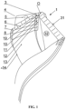
- the twist drill with an alloy tool bit is integrally composed of a tool shank (not shown) comprising a taper shank or a straight shank, and a spiral tool body 4. Grooves are milled on the front spiral cutting surfaces of at least two spiral tool bodies 4, and an alloy tool bit 31 is arranged on the front spiral cutting surface integrally or in a connected mode.
- a cutting surface 13 at the front end in the rotating direction is integrally formed on the alloy tool bit 31 along the axial center of the twist drill with an alloy tool bit 1.
- the spiral cutting surfaces 13 integrally arranged on the two sides of the two spiral tool bodies 4 and the two cutting surfaces 13 integrally arranged with the alloy tool bit 31 are arranged in the same groove respectively.
- the twist drill with an alloy tool bit 1 is integrally provided with two spiral tool bodies 4.
- the surface of the alloy tool bit 31 of each spiral tool body 4 in the cutting direction is a cutting surface.
- the surface on the outer side of the backward cutting surface 13 in the rotating direction is a secondary cutting surface 8.
- the cutting surface 13 is intersected with the secondary cutting surface 8 to form a spiral cutting edge.
- the surface on the back side of the axial front end of the cutting surface 13 is a rear cutting surface 5.
- the rear cutting surfaces on at least two sides are intersected to form a chisel edge.
- the two ends of the chisel edge are chamfered to form a chamfer surface 22 and a chamfer edge 2.
- the cutting surface 13 is intersected with the rear cutting surface 5 to form a cutting edge 6.
- the secondary cutting surface 8 is intersected with the rear cutting surface 5 to form a side edge 7.
- the spiral cutting edge 14 extends to the alloy tool bit 31 to form a secondary cutting edge.
- the spiral secondary cutting surface 8 extends to the alloy tool bit 31 to form a secondary cutting surface 8 of the alloy tool bit 31.
- a central stepped platform 10 with millimeter strength is arranged in a standing mode and a central stepped surface 12 is arranged in a protruding mode.
- the central stepped platform 10 with millimeter strength is connected to the cutting surface 13 of the alloy tool bit 31 in a standing mode.
- the central stepped platform 10 with millimeter strength on the alloy tool bit 31 is intersected with the central stepped surface 12 to form a central edge 11 with millimeter strength.
- the central stepped platform 10 with millimeter strength on the alloy tool bit 31 and the front end of the central stepped surface 12 extending along the axial direction are intersected with the rear cutting surface 5 to form a side micro edge 19 and a cutting middle edge 3.
- the width of the central stepped surface 12 on the alloy tool bit 31 is from the axial center to the cutting surface 13 which is smaller than or equal to one third of the radius of the twist drill with an alloy tool bit 1.
- process holes are formed firstly and then drilling is conducted in the drilling process. Due to the fact that the process holes are formed in the same tool, high stability is achieved. Compared with a common reamer, the tool has the advantages of being more stable and efficient
- a twist drill with the diameter of 20.5 is used for the experiment. Heat treatment and production in the same batch are carried out at the same time on the same material of hard alloy.
- a drilling object is a forged and tempered gear finish turning machining value, the drilling depth is 35 mm, and blind holes are formed.
- the rotating speed of the twist drill with an alloy tool bit 1 in the present disclosure can be increased by 40%, the feed amount is improved by 40%, and the comprehensive drilling efficiency is improved by 0.96 time.
- 731 drilling holes are formed in the twist drill with an alloy tool bit 1 with a common structure.
- 7698 drilling holes are formed in the twist drill with an alloy tool bit 1. The number of drilling holes in the twist drill with an alloy tool bit is increased by more than ten times compared with that of a twist drill with a common structure.
- the twist drill with an alloy tool bit 1 with combined edges in the second embodiment of the present disclosure is comprehensively applied on the basis of the first embodiment.
- a central stepped platform 10 with millimeter strength is arranged in a standing mode and a central stepped surface 12 is convexly arranged on the inner side of the spiral cutting surface 13 of the twist drill with an alloy tool bit 1 with combined edges near the axial center O.
- the central stepped platform 10 with millimeter strength is connected to the cutting surface 13 in a standing mode.
- the central stepped platform 10 with millimeter strength is intersected with the central stepped surface 12 to form a central edge 11 with millimeter strength.
- Cooling holes 32 are integrally formed in a tool shank and a spiral tool body of the twist drill with an alloy tool bit 1.
Landscapes
- Engineering & Computer Science (AREA)
- Mechanical Engineering (AREA)
- Drilling Tools (AREA)
Claims (14)
- Ein Spiralbohrer (1) mit einem Legierungswerkzeugeinsatz (31), aufweisendeinen Schaft, einen spiralförmigen Werkzeugkörper (4) undeinen Legierungswerkzeugeinsatz (31), wobei der Spiralbohrer mit dem Legierungswerkzeugeinsatz einstückig mit mindestens zwei spiralförmigen Werkzeugkörpern (4) versehen ist, die Oberfläche jedes spiralförmigen Werkzeugkörpers (4) in der Schneidrichtung eine spiralförmige Schneidfläche (13) ist, die Oberfläche auf der Außenseite der rückwärtigen spiralförmigen Schneidfläche (13) in der Drehrichtung eine spiralförmige sekundäre Schneidfläche (8) ist, die spiralförmige Schneidfläche (13) sich mit der spiralförmigen sekundären Schneidfläche (8) schneidet, um eine spiralförmige Schneidkante (14) zu bilden,die Fläche auf der Rückseite des axialen vorderen Endes der spiralförmigen Schneidfläche (13) eine hintere Schneidfläche (5) ist, die hinteren Schneidflächen (5) auf mindestens zwei Seiten geschnitten werden, um eine Meißelkante zu bilden, die spiralförmige Schneidfläche (13) mit der hinteren Schneidfläche (5) geschnitten wird, um eine Schneidkante (6) zu bilden, und die spiralförmige sekundäre Schneidfläche (8) mit der hinteren Schneidfläche (5) geschnitten wird, um eine Seitenkante (7) zu bilden;der Spiralbohrer mit dem Legierungswerkzeugeinsatz besteht einstückig aus dem Werkzeugschaft und dem Spiralwerkzeugkörper (4), in die vordere Spiralschneidfläche (13) des Spiralwerkzeugkörpers (4) ist eine Nut eingefräst, der Legierungswerkzeugeinsatz (31) ist einstückig auf der vorderen Spiralschneidfläche angeordnet, die Spiralschneidflächen (13) auf den beiden Seiten und eine Schneidfläche (13) des Legierungswerkzeugeinsatz jeweils in der gleichen Nut angeordnet sind, die Spiralschneidkante (14) sich zu dem Legierungswerkzeugeinsatz erstreckt, um eine sekundäre Schneidkante (14) zu bilden, und die spiralförmige sekundäre Schneidfläche (8) sich zu dem Legierungswerkzeugeinsatz erstreckt, um eine sekundäre Schneidfläche (8) zu bilden;eine zentrale abgestufte Plattform (10) ist auf der Schneidfläche (13) nahe der axialen Mitte des Legierungswerkzeugeinsatz des Spiralbohrers angeordnet, wobei sich der Legierungswerkzeugeinsatz in einem stehenden Modus befindet;eine zentrale abgestufte Fläche (12) ist auf der Innenseite der zentralen abgestuften Plattform (10) angeordnet, die in die Drehrichtung vorsteht;die zentrale abgestufte Plattform (10) sich mit der hinteren Schneidfläche (5) schneidet, um eine seitliche Mikrokante (19) zu bilden;die zentrale abgestufte Plattform (10) sich mit der zentralen abgestuften Fläche (12) schneidet, um eine zentrale Kante (11) zu bilden;die hintere Schneidfläche (5) sich mit der zentralen abgestuften Fläche (12) schneidet, um eine mittlere Schneidkante (3) zu bilden; unddadurch gekennzeichnet, dassdie Breite der zentralen gestuften Fläche (12) auf dem Legierungswerkzeugeinsatz von der axialen Mitte bis zur Schneidfläche (13) kleiner oder gleich einem Drittel des Radius des Spiralbohrers mit dem Legierungswerkzeugeinsatz ist.
- Der Spiralbohrer mit dem Legierungswerkzeugeinsatz nach Anspruch 1, wobei ein Abzweiglochtische (23) konkav auf der Schneidfläche (13) der sekundären Schneidkante (14) auf dem Legierungswerkzeugeinsatz des Spiralbohrers mit dem Legierungswerkzeugeinsatz in schrittweise von der axialen Mitte zum Außenumfang angeordnet ist;die Innenseite des Abzweiglochtisches (23) vorsteht, um eine Abzweigschneidfläche (24) zu bilden, die Abzweigschneidfläche (24) sich mit der hinteren Schneidfläche (5) schneidet, um die Schneidkante (6) zu bilden;der Abzweiglochtisch (23) sich mit der hinteren Schneidfläche (5) schneidet, um eine seitliche Mikrokante (19) zu bilden;der Abzweiglochtisch (23) mit der an der Innenseite vorstehenden Schneidfläche (13) geschnitten wird, um eine Abzweigschneidkante (26) zu bilden; unddie Zweigschneidfläche (24) von der axialen Mitte bis zur Schneidfläche (13) größer als oder gleich einem Drittel des Radius des Spiralbohrers mit dem Legierungswerkzeugeinsatz und kleiner als oder gleich zwei Drittel des Radius des Spiralbohrers mit dem Legierungswerkzeugeinsatz ist.
- Der Spiralbohrer mit dem Legierungswerkzeugeinsatz nach Anspruch 1, wobeieine Mikroschneidfläche (18) ist auf der Schneidfläche (13) des Legierungswerkzeugeinsatz von der sekundären Schneidkante (14) in Richtung der axialen Mittellinie auf der Schneidfläche (13) des Legierungswerkzeugeinsatz des Spiralbohrers mit dem Legierungswerkzeugeinsatz (1) konkav ausgebildet;eine Mikro-Verstärkungs-Spannungserweiterungstabelle (20) ist auf der Innenseite der Mikroschneidfläche (18) in einem stehenden Modus ausgebildet;die Mikroschneidfläche (18) mit der sekundären Schneidfläche (8) am Außenumfang geschnitten wird, um eine Mikroschneidkante (17) zu bilden;die Mikroschneidfläche (18) mit der hinteren Schneidfläche (5) geschnitten wird, um eine Mikroschneidkante (16) zu bilden; unddie Mikroverfestigungsspannungsverlängerungstisch (20) mit der hinteren Schneidfläche (5) geschnitten wird, um eine Seitenmikrokante (19) zu bilden.
- Der Spiralbohrer mit dem Legierungswerkzeugeinsatz nach Anspruch 1, wobeiauf der Schneidfläche (13) der sekundären Scheidkante (14) am Legierungswerkzeugeinsatz des Spiralbohrers mit dem Legierungswerkzeugeinsatz stufenweise von der axialen Mitte zum Außenumfang ein Abzweiglochtisches (23) einstückig konkav angeordnet ist;die Innenseite des Abzweiglochtisches (23) vorsteht, um eine Abzweigschneidfläche (24) zu bilden, die Abzweigschneidfläche (24) sich mit der hinteren Schneidfläche (5) schneidet, um die Schneidkante (6) zu bilden;der Abzweiglochtisch (23) sich mit der hinteren Schneidfläche (5) schneidet, um eine seitliche Mikrokante (19) zu bilden;der Abzweiglochtisch (23) sich mit der Schneidfläche (13) schneidet, die auf der Innenseite vorsteht, um eine Abzweigschneidkante (26) zu bilden.
- Der Spiralbohrer mit dem Legierungswerkzeugeinsatz nach Anspruch 1, wobeieine Mikroschneidfläche (18) konkav auf der Schneidfläche (13) des Legierungswerkzeugeinsatz von der sekundären Schneidkante (14) in Richtung der axialen Mittelrichtung auf der Schneidfläche (13) des Legierungswerkzeugeinsatz des Spiralbohrers mit dem Legierungswerkzeugeinsatz einstückig ausgebildet ist;auf der Innenseite der Mikroschneidfläche (18) im stehenden Zustand ein Mikroverfestigungsspannungsverlängerungstisch (20) ausgebildet ist;die Mikroschneidfläche (18) wird mit der sekundären Schneidfläche (8) am Außenumfang geschnitten, um eine Mikroschneidkante (17) zu bilden;die Mikroschneidfläche (18) mit der hinteren Schneidfläche (5) geschnitten wird, um eine Mikroschneidkante (16) zu bilden; undder Mikroverfestigungsspannungsverlängerungstisch mit der hinteren Schneidfläche (5) geschnitten wird, um eine seitliche Mikrokante (19) zu bilden.
- Der Spiralbohrer mit dem Legierungswerkzeugeinsatz nach Anspruch 1, wobeiauf der Schneidfläche (13) der sekundären Schneidkante (14) am Legierungswerkzeugeinsatz des Spiralbohrers mit dem Legierungswerkzeugeinsatz schrittweise von der axialen Mitte zum Außenumfang hin ein Abzweiglochtisches (23) konkav angeordnet ist;die Innenseite des Abzweiglochtisches (23) vorsteht, um eine Abzweigschneidfläche (24) zu bilden, wobei die Abzweigschneidfläche (24) mit der hinteren Schneidfläche (5) geschnitten wird, um die Schneidkante (6) zu bilden;der Abzweiglochtisch (23) wird mit der hinteren Schneidfläche (5) gekreuzt, um eine seitliche Mikrokante (19) zu bilden;die Abzweiglochtabelle (23) mit der Schneidfläche (13) geschnitten wird, die auf der Innenseite vorsteht, um eine Abzweigschneidkante (26) zu bilden;eine Mikroschneidfläche (18) konkav auf der Schneidfläche (13) des Legierungswerkzeugeinsatz von der sekundären Schneidkante (14) in Richtung der axialen Mittelrichtung auf der Schneidfläche (13) des Legierungswerkzeugeinsatz des Spiralbohrers mit dem Legierungswerkzeugeinsatz einstückig ausgebildet ist;eine Mikroverfestigungsspannungsverlängerungstisch (20) auf der Innenseite der Mikroschneidfläche (18) in einem stehenden Modus gebildet wird;die Mikroschneidfläche (18) mit der sekundären Schneidfläche (8) auf dem äußeren Umfang geschnitten wird, um eine Mikroschneidkante (17) zu bilden;die Mikroschneidfläche (18) wird mit der hinteren Schneidfläche (5) geschnitten, um eine Mikroschneidkante (16) zu bilden;und der Mikroverfestigungsspannungsverlängerungstisch (20) wird mit der hinteren Schneidfläche (5) geschnitten, um eine seitliche Mikrokante (19) zu bilden.
- Der Spiralbohrer mit dem Legierungswerkzeugeinsatz nach Anspruch 1, wobeiein Abzweiglochtisch (23) auf der Schneidfläche (13) der sekundäre Schneidkante (14) am Legierungswerkzeugeinsatz des Spiralbohrers mit dem Legierungswerkzeugeinsatz stufenweise von der axialen Mitte zum Außenumfang einstückig angeordnet ist;die Innenseite des Abzweiglochtisches (23) vorsteht, um eine Abzweigschneidfläche (24) zu bilden, wobei die Abzweigschneidfläche (24) mit der hinteren Schneidfläche (5) geschnitten wird, um die Schneidkante (6) zu bilden;der Abzweiglochtisch (23) wird mit der hinteren Schneidfläche (5) gekreuzt, um eine seitliche Mikrokante (19) zu bilden;der Abzweiglochtisch (23) mit der auf der Innenseite vorstehenden Schneidfläche (13) geschnitten wird, um eine Abzweigschneidkante (26) zu bilden;eine Mikroschneidfläche (18) konkav auf der Schneidfläche (13) des Legierungswerkzeugeinsatz von der sekundären Schneidkante (14) in Richtung der axialen Mittelrichtung auf der Schneidfläche (13) des Legierungswerkzeugeinsatz des Spiralbohrers mit dem Legierungswerkzeugeinsatz einstückig ausgebildet ist;eine Mikroverfestigungsspannungsverlängerungstisch (20) auf der Innenseite der Mikroschneidfläche (18) in einem stehenden Modus gebildet wird;die Mikroschneidfläche (18) mit der sekundären Schneidfläche (8) auf dem äußeren Umfang geschnitten wird, um eine Mikroschneidkante (17) zu bilden;die Mikroschneidfläche (18) wird mit der hinteren Schneidfläche (5) geschnitten, um eine Mikroschneidkante (16) zu bilden;und der Mikroverfestigungsspannungsverlängerungstisch (20) wird mit der hinteren Schneidfläche (5) geschnitten, um eine seitliche Mikrokante (19) zu bilden.
- Der Spiralbohrer mit dem Legierungswerkzeugeinsatz nach einem der Ansprüche 1 bis 7, wobeimindestens eine oder mehrere Kerbkanten an einer Legierungswerkzeugeinsatzschneide (6) des Spiralbohrers mit dem Legierungsmeißel angeordnet sind;und jede Kerbkante erstreckt sich in Richtung der hinteren Schneidfläche (5), um eine Nut zu bilden.
- Der Spiralbohrer mit dem Legierungswerkzeugeinsatz nach einem der Ansprüche 1 bis 7, wobei mindestens eine oder mehrere stehende Stufen und mindestens eine oder mehrere vorstehende hintere Schneidflächen (5) an der hinteren Schneidfläche (5), an der sich der Legierungswerkzeugeinsatz des Spiralbohrers mit dem Legierungswerkzeugeinsatz befindet, von der axialen Mitte aus so angeordnet sind, dass die Höhe der hinteren Schneidfläche (5) in Richtung einer äußeren Seitenkante (7) reduziert ist, die stehende Stufe mit der Schneidfläche (13) am vorderen Ende in der Drehrichtung geschnitten wird, um mindestens eine oder mehrere stehende Stufenkanten zu bilden, und die mindestens eine oder mehreren vorstehenden hinteren Schneidflächen (5) mit der Schneidfläche (13) am vorderen Ende in der Drehrichtung geschnitten werden, um mindestens eine oder mehrere vorstehende Schneidkanten (6) zu bilden.
- Der Spiralbohrer mit Legierungswerkzeugeinsatz nach einem der Ansprüche 1 bis 7, wobei mindestens eine oder mehrere stehende Stufen und mindestens eine oder mehrere vorstehende hintere Schneidflächen (5) an der hinteren Schneidfläche (5), an der sich der Legierungswerkzeugeinsatz des Spiralbohrers mit dem Legierungswerkzeugeinsatz befindet, von der axialen Mitte aus so angeordnet sind, dass die Höhe der hinteren Schneidfläche (5) in Richtung einer äußeren Seitenkante (7) reduziert ist, die mindestens eine oder mehrere stehende Stufen mit der Schneidfläche (13) am vorderen Ende in Drehrichtung unter Bildung mindestens einer oder mehrerer stehender Stufenkanten geschnitten werden, und die mindestens eine oder vorstehenden hinteren Schneidflächen (5) mit der Schneidfläche (13) unter Bildung mindestens einer vorstehenden Schneidkante (6) geschnitten werden;
und mindestens eine oder mehrere Kerbkanten an den mindestens einen oder mehreren stufenweise angeordneten Schneidkanten (6) des Legierungswerkzeugeinsatz angeordnet sind und jede Kerbkante sich zur hinteren Schneidfläche hin erstreckt, um eine Nut zu bilden. - Der Spiralbohrer mit dem Legierungswerkzeugeinsatz nach einem der Ansprüche 1 bis 7, wobei die hinteren Schneidflächen (5) auf den beiden Seiten des vorderen Endes des Legierungswerkzeugeinsatz des Spiralbohrers mit dem Legierungswerkzeugeinsatz sich in der axialen Mitte schneiden, um eine Fasenfläche (22), eine Fasenschneide und die Meißelschneide zu bilden.
- Der Spiralbohrer mit Legierungswerkzeugeinsatz nach einem der Ansprüche 1 bis 7, wobei in den Werkzeugschaft und den spiralförmigen Werkzeugkörper (4) des Spiralbohrers mit dem legierten Werkzeugeinsatz Kühlbohrungen eingearbeitet sind.
- Der Spiralbohrer mit dem Legierungswerkzeugeinsatz nach einem der Ansprüche 1 bis 7, wobeider eingeschlossene Winkel, der dadurch gebildet wird, dass die Schneidkante (6) an der äußersten Seite des Legierungswerkzeugeinsatz des Spiralbohrers mit dem Legierungswerkzeugeinsatz (1) mit der spiralförmigen sekundären Schneidkante (14) geschnitten wird, ein spitzer Winkel ist; oderder eingeschlossene Winkel, der durch das Schneiden der Schneide (6) auf der äußersten Seite des Legierungswerkzeugeinsatz des Spiralbohrers mit dem Legierungswerkzeugeinsatz mit der spiralförmigen sekundären Schneidkante (14) gebildet wird, ein rechter Winkel ist; oderder eingeschlossene Winkel, der durch das Schneiden der Schneide (6) auf der äußersten Seite des Legierungswerkzeugeinsatz des Spiralbohrers mit dem Legierungswerkzeugeinsatz mit der spiralförmigen sekundären Schneidkante (14) gebildet wird, ein stumpfer Winkel ist.
- Der Spiralbohrer mit Legierungswerkzeugeinsatz nach einem der Ansprüche 1 und 3 bis 7, wobeider Werkzeugschaft des Spiralbohrers Legierungswerkzeugeinsatz ist ein Zylinderschaft;oder der Werkzeugschaft Spiralbohrers mit dem Legierungswerkzeugeinsatz ist ein Kegelschaft; unddie Breite einer Zweigschneidfläche (24) des Legierungswerkzeugeinsatz größer oder gleich einem Drittel des Radius des Spiralbohrers mit Legierungswerkzeugeinsatz und kleiner oder gleich zwei Dritteln des Radius des Spiralbohrers mit dem Legierungswerkzeugeinsatz ist.
Applications Claiming Priority (9)
| Application Number | Priority Date | Filing Date | Title |
|---|---|---|---|
| CN202010428077.4A CN112139569A (zh) | 2020-05-17 | 2020-05-17 | 组合刃合金刀头麻花钻 |
| CN202010428122.6A CN112139570A (zh) | 2020-05-17 | 2020-05-17 | 定孔合金刀头麻花钻 |
| CN202010428158.4A CN111730111A (zh) | 2020-05-17 | 2020-05-17 | 合金刀头麻花钻 |
| CN202010428124.5A CN112139571A (zh) | 2020-05-17 | 2020-05-17 | 加强合金刀头麻花钻 |
| CN202010428191.7A CN112453504A (zh) | 2020-05-17 | 2020-05-17 | 分孔合金刀头麻花钻 |
| CN202010428080.6A CN111730110A (zh) | 2020-05-17 | 2020-05-17 | 分切式合金刀头麻花钻 |
| CN202010428078.9A CN112191893A (zh) | 2020-05-17 | 2020-05-17 | 定位合金刀头麻花钻 |
| CN202010428157.XA CN112191894A (zh) | 2020-05-17 | 2020-05-17 | 定心合金刀头麻花钻 |
| PCT/CN2021/000099 WO2021232823A1 (zh) | 2020-05-17 | 2021-05-12 | 合金刀头麻花钻 |
Publications (4)
| Publication Number | Publication Date |
|---|---|
| EP4155016A1 EP4155016A1 (de) | 2023-03-29 |
| EP4155016A4 EP4155016A4 (de) | 2023-11-15 |
| EP4155016B1 true EP4155016B1 (de) | 2025-07-09 |
| EP4155016C0 EP4155016C0 (de) | 2025-07-09 |
Family
ID=78707705
Family Applications (1)
| Application Number | Title | Priority Date | Filing Date |
|---|---|---|---|
| EP21809185.8A Active EP4155016B1 (de) | 2020-05-17 | 2021-05-12 | Spiralbohrer mit legierungswerkzeugspitze |
Country Status (4)
| Country | Link |
|---|---|
| US (1) | US20230191507A1 (de) |
| EP (1) | EP4155016B1 (de) |
| WO (1) | WO2021232823A1 (de) |
| ZA (1) | ZA202212762B (de) |
Families Citing this family (3)
| Publication number | Priority date | Publication date | Assignee | Title |
|---|---|---|---|---|
| CN112894488B (zh) * | 2021-03-06 | 2023-01-10 | 山东瑞尔达科技集团股份有限公司 | 一种带有刀具破损的自动报警装置的金属切削机床 |
| EP4342611A4 (de) * | 2021-06-06 | 2025-01-29 | Shandong Old Roughneck Machinery Technology Co., Ltd. | Mikroverstärkter konzentrischer spiralbohrer |
| USD1039933S1 (en) * | 2021-12-20 | 2024-08-27 | William Norton | Driver |
Family Cites Families (14)
| Publication number | Priority date | Publication date | Assignee | Title |
|---|---|---|---|---|
| WO2008046520A1 (de) * | 2006-10-13 | 2008-04-24 | Kennametal Inc. | Bohrerspitze für ein bohrwerkzeug |
| JP2011514263A (ja) * | 2008-03-19 | 2011-05-06 | リー、シーチン | らせん状差込バイト |
| CN103381496A (zh) * | 2012-05-03 | 2013-11-06 | 李仕清 | 复合定位切削的螺旋刀具 |
| CN103706845A (zh) * | 2012-10-01 | 2014-04-09 | 李仕清 | 复合定位切削的螺旋刀具 |
| DE102014010922B4 (de) * | 2014-07-28 | 2023-10-19 | Sundwiger Drehtechnik Gmbh | Gelöteter Konturbohrer für bleifreie und bleiarme Werkstoffe |
| CN108262506A (zh) * | 2016-12-30 | 2018-07-10 | 李仕清 | 分径移位麻花钻 |
| GB2562730B (en) * | 2017-05-22 | 2020-07-01 | Gkn Aerospace Sweden Ab | Cooled drill |
| CN112191893A (zh) * | 2020-05-17 | 2021-01-08 | 李仕清 | 定位合金刀头麻花钻 |
| CN112139569A (zh) * | 2020-05-17 | 2020-12-29 | 李仕清 | 组合刃合金刀头麻花钻 |
| CN112191894A (zh) * | 2020-05-17 | 2021-01-08 | 李仕清 | 定心合金刀头麻花钻 |
| CN111730111A (zh) * | 2020-05-17 | 2020-10-02 | 李仕清 | 合金刀头麻花钻 |
| CN112139570A (zh) * | 2020-05-17 | 2020-12-29 | 李仕清 | 定孔合金刀头麻花钻 |
| CN112139571A (zh) * | 2020-05-17 | 2020-12-29 | 李仕清 | 加强合金刀头麻花钻 |
| CN112453504A (zh) * | 2020-05-17 | 2021-03-09 | 李仕清 | 分孔合金刀头麻花钻 |
-
2021
- 2021-05-12 WO PCT/CN2021/000099 patent/WO2021232823A1/zh not_active Ceased
- 2021-05-12 US US17/925,466 patent/US20230191507A1/en active Pending
- 2021-05-12 EP EP21809185.8A patent/EP4155016B1/de active Active
-
2022
- 2022-11-23 ZA ZA2022/12762A patent/ZA202212762B/en unknown
Also Published As
| Publication number | Publication date |
|---|---|
| US20230191507A1 (en) | 2023-06-22 |
| EP4155016A1 (de) | 2023-03-29 |
| EP4155016C0 (de) | 2025-07-09 |
| WO2021232823A1 (zh) | 2021-11-25 |
| ZA202212762B (en) | 2023-03-29 |
| EP4155016A4 (de) | 2023-11-15 |
Similar Documents
| Publication | Publication Date | Title |
|---|---|---|
| US4189266A (en) | Rotary drill bit for hand-held power drills | |
| EP4155016B1 (de) | Spiralbohrer mit legierungswerkzeugspitze | |
| RU2455127C2 (ru) | Сверло для вырезания отверстия с плоским основанием | |
| JP2011514263A (ja) | らせん状差込バイト | |
| CN107206510A (zh) | 单刃深孔钻 | |
| CN210254406U (zh) | 一种直线型三尖-细齿状钻铣复合刀具 | |
| WO2018120274A1 (zh) | 分径移位麻花钻 | |
| US9415450B2 (en) | Tool head and method for machining a metallic workpiece | |
| CN112191894A (zh) | 定心合金刀头麻花钻 | |
| JP3851804B2 (ja) | 刃先交換式ツイストドリル | |
| CN112139571A (zh) | 加强合金刀头麻花钻 | |
| CN112139569A (zh) | 组合刃合金刀头麻花钻 | |
| CN103706845A (zh) | 复合定位切削的螺旋刀具 | |
| CN112191893A (zh) | 定位合金刀头麻花钻 | |
| CN111730111A (zh) | 合金刀头麻花钻 | |
| CN215509117U (zh) | 一种钻头 | |
| JPS6125941Y2 (de) | ||
| CN103706844A (zh) | 复合刃中心钻或复合刃锪钻 | |
| CN113510280A (zh) | 微强化同心麻花钻 | |
| CN210937446U (zh) | 一种铰刀及其牙轮齿孔精铰钻床 | |
| CN112453504A (zh) | 分孔合金刀头麻花钻 | |
| CN112139570A (zh) | 定孔合金刀头麻花钻 | |
| CN114918462A (zh) | 一种铲钻刀片 | |
| CN203711944U (zh) | 耐用型钻头 | |
| CN207309027U (zh) | 一种钻尖具有球面和锥面结构的钻头 |
Legal Events
| Date | Code | Title | Description |
|---|---|---|---|
| STAA | Information on the status of an ep patent application or granted ep patent |
Free format text: STATUS: THE INTERNATIONAL PUBLICATION HAS BEEN MADE |
|
| PUAI | Public reference made under article 153(3) epc to a published international application that has entered the european phase |
Free format text: ORIGINAL CODE: 0009012 |
|
| STAA | Information on the status of an ep patent application or granted ep patent |
Free format text: STATUS: REQUEST FOR EXAMINATION WAS MADE |
|
| 17P | Request for examination filed |
Effective date: 20221215 |
|
| AK | Designated contracting states |
Kind code of ref document: A1 Designated state(s): AL AT BE BG CH CY CZ DE DK EE ES FI FR GB GR HR HU IE IS IT LI LT LU LV MC MK MT NL NO PL PT RO RS SE SI SK SM TR |
|
| DAV | Request for validation of the european patent (deleted) | ||
| DAX | Request for extension of the european patent (deleted) | ||
| A4 | Supplementary search report drawn up and despatched |
Effective date: 20231016 |
|
| RIC1 | Information provided on ipc code assigned before grant |
Ipc: B23B 51/00 20060101ALI20231010BHEP Ipc: B23B 51/02 20060101AFI20231010BHEP |
|
| STAA | Information on the status of an ep patent application or granted ep patent |
Free format text: STATUS: EXAMINATION IS IN PROGRESS |
|
| 17Q | First examination report despatched |
Effective date: 20240709 |
|
| GRAP | Despatch of communication of intention to grant a patent |
Free format text: ORIGINAL CODE: EPIDOSNIGR1 |
|
| STAA | Information on the status of an ep patent application or granted ep patent |
Free format text: STATUS: GRANT OF PATENT IS INTENDED |
|
| INTG | Intention to grant announced |
Effective date: 20250227 |
|
| GRAS | Grant fee paid |
Free format text: ORIGINAL CODE: EPIDOSNIGR3 |
|
| GRAA | (expected) grant |
Free format text: ORIGINAL CODE: 0009210 |
|
| STAA | Information on the status of an ep patent application or granted ep patent |
Free format text: STATUS: THE PATENT HAS BEEN GRANTED |
|
| AK | Designated contracting states |
Kind code of ref document: B1 Designated state(s): AL AT BE BG CH CY CZ DE DK EE ES FI FR GB GR HR HU IE IS IT LI LT LU LV MC MK MT NL NO PL PT RO RS SE SI SK SM TR |
|
| REG | Reference to a national code |
Ref country code: GB Ref legal event code: FG4D |
|
| REG | Reference to a national code |
Ref country code: CH Ref legal event code: EP |
|
| REG | Reference to a national code |
Ref country code: IE Ref legal event code: FG4D |
|
| REG | Reference to a national code |
Ref country code: DE Ref legal event code: R096 Ref document number: 602021033898 Country of ref document: DE |
|
| U01 | Request for unitary effect filed |
Effective date: 20250729 |
|
| U07 | Unitary effect registered |
Designated state(s): AT BE BG DE DK EE FI FR IT LT LU LV MT NL PT RO SE SI Effective date: 20250805 |
|
| PG25 | Lapsed in a contracting state [announced via postgrant information from national office to epo] |
Ref country code: IS Free format text: LAPSE BECAUSE OF FAILURE TO SUBMIT A TRANSLATION OF THE DESCRIPTION OR TO PAY THE FEE WITHIN THE PRESCRIBED TIME-LIMIT Effective date: 20251109 |
|
| PG25 | Lapsed in a contracting state [announced via postgrant information from national office to epo] |
Ref country code: NO Free format text: LAPSE BECAUSE OF FAILURE TO SUBMIT A TRANSLATION OF THE DESCRIPTION OR TO PAY THE FEE WITHIN THE PRESCRIBED TIME-LIMIT Effective date: 20251009 |
|
| PG25 | Lapsed in a contracting state [announced via postgrant information from national office to epo] |
Ref country code: HR Free format text: LAPSE BECAUSE OF FAILURE TO SUBMIT A TRANSLATION OF THE DESCRIPTION OR TO PAY THE FEE WITHIN THE PRESCRIBED TIME-LIMIT Effective date: 20250709 |
|
| PG25 | Lapsed in a contracting state [announced via postgrant information from national office to epo] |
Ref country code: GR Free format text: LAPSE BECAUSE OF FAILURE TO SUBMIT A TRANSLATION OF THE DESCRIPTION OR TO PAY THE FEE WITHIN THE PRESCRIBED TIME-LIMIT Effective date: 20251010 |
|
| PG25 | Lapsed in a contracting state [announced via postgrant information from national office to epo] |
Ref country code: PL Free format text: LAPSE BECAUSE OF FAILURE TO SUBMIT A TRANSLATION OF THE DESCRIPTION OR TO PAY THE FEE WITHIN THE PRESCRIBED TIME-LIMIT Effective date: 20250709 |
|
| PG25 | Lapsed in a contracting state [announced via postgrant information from national office to epo] |
Ref country code: RS Free format text: LAPSE BECAUSE OF FAILURE TO SUBMIT A TRANSLATION OF THE DESCRIPTION OR TO PAY THE FEE WITHIN THE PRESCRIBED TIME-LIMIT Effective date: 20251009 |
|
| PG25 | Lapsed in a contracting state [announced via postgrant information from national office to epo] |
Ref country code: ES Free format text: LAPSE BECAUSE OF FAILURE TO SUBMIT A TRANSLATION OF THE DESCRIPTION OR TO PAY THE FEE WITHIN THE PRESCRIBED TIME-LIMIT Effective date: 20250709 |
|
| PG25 | Lapsed in a contracting state [announced via postgrant information from national office to epo] |
Ref country code: SM Free format text: LAPSE BECAUSE OF FAILURE TO SUBMIT A TRANSLATION OF THE DESCRIPTION OR TO PAY THE FEE WITHIN THE PRESCRIBED TIME-LIMIT Effective date: 20250709 |
|
| PGFP | Annual fee paid to national office [announced via postgrant information from national office to epo] |
Ref country code: GB Payment date: 20260313 Year of fee payment: 6 |
|
| PG25 | Lapsed in a contracting state [announced via postgrant information from national office to epo] |
Ref country code: CZ Free format text: LAPSE BECAUSE OF FAILURE TO SUBMIT A TRANSLATION OF THE DESCRIPTION OR TO PAY THE FEE WITHIN THE PRESCRIBED TIME-LIMIT Effective date: 20250709 |
|
| PG25 | Lapsed in a contracting state [announced via postgrant information from national office to epo] |
Ref country code: SK Free format text: LAPSE BECAUSE OF FAILURE TO SUBMIT A TRANSLATION OF THE DESCRIPTION OR TO PAY THE FEE WITHIN THE PRESCRIBED TIME-LIMIT Effective date: 20250709 |