EP4155016B1 - Foret hélicoïdal avec un insert en alliage - Google Patents
Foret hélicoïdal avec un insert en alliage Download PDFInfo
- Publication number
- EP4155016B1 EP4155016B1 EP21809185.8A EP21809185A EP4155016B1 EP 4155016 B1 EP4155016 B1 EP 4155016B1 EP 21809185 A EP21809185 A EP 21809185A EP 4155016 B1 EP4155016 B1 EP 4155016B1
- Authority
- EP
- European Patent Office
- Prior art keywords
- cutting surface
- tool bit
- alloy tool
- cutting
- edge
- Prior art date
- Legal status (The legal status is an assumption and is not a legal conclusion. Google has not performed a legal analysis and makes no representation as to the accuracy of the status listed.)
- Active
Links
Images

Classifications
-
- B—PERFORMING OPERATIONS; TRANSPORTING
- B23—MACHINE TOOLS; METAL-WORKING NOT OTHERWISE PROVIDED FOR
- B23B—TURNING; BORING
- B23B51/00—Tools for drilling machines
- B23B51/02—Twist drills
-
- B—PERFORMING OPERATIONS; TRANSPORTING
- B23—MACHINE TOOLS; METAL-WORKING NOT OTHERWISE PROVIDED FOR
- B23B—TURNING; BORING
- B23B51/00—Tools for drilling machines
- B23B51/0002—Drills with connected cutting heads, e.g. with non-exchangeable cutting heads; Drills with a single insert extending across the rotational axis and having at least two radially extending cutting edges in the working position
-
- B—PERFORMING OPERATIONS; TRANSPORTING
- B23—MACHINE TOOLS; METAL-WORKING NOT OTHERWISE PROVIDED FOR
- B23B—TURNING; BORING
- B23B51/00—Tools for drilling machines
- B23B51/009—Stepped drills
-
- B—PERFORMING OPERATIONS; TRANSPORTING
- B23—MACHINE TOOLS; METAL-WORKING NOT OTHERWISE PROVIDED FOR
- B23B—TURNING; BORING
- B23B2251/00—Details of tools for drilling machines
- B23B2251/08—Side or plan views of cutting edges
- B23B2251/085—Discontinuous or interrupted cutting edges
-
- B—PERFORMING OPERATIONS; TRANSPORTING
- B23—MACHINE TOOLS; METAL-WORKING NOT OTHERWISE PROVIDED FOR
- B23B—TURNING; BORING
- B23B2251/00—Details of tools for drilling machines
- B23B2251/14—Configuration of the cutting part, i.e. the main cutting edges
-
- B—PERFORMING OPERATIONS; TRANSPORTING
- B23—MACHINE TOOLS; METAL-WORKING NOT OTHERWISE PROVIDED FOR
- B23B—TURNING; BORING
- B23B2251/00—Details of tools for drilling machines
- B23B2251/40—Flutes, i.e. chip conveying grooves
- B23B2251/406—Flutes, i.e. chip conveying grooves of special form not otherwise provided for
Definitions
- the drilling tool used in machining is composed of a chisel edge, a cutting edge, a spiral cutting edge and a side edge.
- the cutting edge is located on a spiral cutting surface and is of a single co-located cutting structure.
- the cutting edge is in the centrifugal force conduction range of rotary cutting.
- the cutting edge is subjected to rotary cutting force and centrally outward conduction force at the same time.
- the cutting edge at the intersection of the cutting edge and the spiral cutting edge is always easy to damage under the action of double forces.
- An existing hole machining tool swings due to the fact that the structure is not absolutely balanced during drilling.
- the spiral cutting surface and the spiral cutting edge are damaged due to the fact that the tool is stabilized only through the spiral cutting surface.
- CN 103 381 496 A discloses a twist drill with an alloy tool bit.
- the present disclosure aims to provide a twist drill with an alloy tool bit in view of the above-mentioned problems.
- the tool has the function of blocking conduction force, and is high in heat dissipation efficiency and strength and long in service life.
- the tool is easy to position in the drilling process, and the drilling precision is high. People generally thought that the smoother the surface is, the higher the strength is. According to new theories in recent years, the strength of the surface with tiny gaps is higher, but essential structural characteristics of the substance are not revealed. Under the condition that two solids are the same in volumes, the surface area of the dispersed small-volume solid is larger than the surface area of the whole solid. When the whole structure of the solid reaches a certain volume limit, even diamond is broken.
- the sum of the stress strengths of the small-size solids is far larger than the stress strength of the whole solid under the condition of volume stress.
- the millimeter magnitude has the most obvious high-strength characteristic, namely the millimeter strength.
- the twist drill with an alloy tool bit is applied in millimeter strength.
- the twist drill with the alloy tool bit has the following beneficial effects.
- a twist drill with the diameter of 20.0 is used for the experiment. Heat treatment and production in the same batch are carried out at the same time.
- a drilling object is a forged and tempered gear finish turning machining value, the drilling depth is 35 mm, and blind holes are formed.
- the rotating speed of the twist drill with an alloy tool bit can be increased by 40%, the feed amount is improved by 40%, and the comprehensive drilling efficiency is improved by more than one time.
- the number of drilling holes in the twist drill with an alloy tool bit is increased by more than ten times compared with that of a twist drill with a common structure.
- twist drill with an alloy tool bit in the present disclosure are described in detail with reference to the attached figures.
- the twist drill with the alloy tool bit is mainly described as an example of a tool with two spiral tool bodies integrally.
- the twist drill with the alloy tool bit 1 relates to a drilling tool for machining.
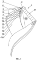
- the twist drill with an alloy tool bit is integrally composed of a tool shank (not shown) comprising a taper shank or a straight shank, and a spiral tool body 4. Grooves are milled on the front spiral cutting surfaces of at least two spiral tool bodies 4, and an alloy tool bit 31 is arranged on the front spiral cutting surface integrally or in a connected mode.
- a cutting surface 13 at the front end in the rotating direction is integrally formed on the alloy tool bit 31 along the axial center of the twist drill with an alloy tool bit 1.
- the spiral cutting surfaces 13 integrally arranged on the two sides of the two spiral tool bodies 4 and the two cutting surfaces 13 integrally arranged with the alloy tool bit 31 are arranged in the same groove respectively.
- the twist drill with an alloy tool bit 1 is integrally provided with two spiral tool bodies 4.
- the surface of the alloy tool bit 31 of each spiral tool body 4 in the cutting direction is a cutting surface.
- the surface on the outer side of the backward cutting surface 13 in the rotating direction is a secondary cutting surface 8.
- the cutting surface 13 is intersected with the secondary cutting surface 8 to form a spiral cutting edge.
- the surface on the back side of the axial front end of the cutting surface 13 is a rear cutting surface 5.
- the rear cutting surfaces on at least two sides are intersected to form a chisel edge.
- the two ends of the chisel edge are chamfered to form a chamfer surface 22 and a chamfer edge 2.
- the cutting surface 13 is intersected with the rear cutting surface 5 to form a cutting edge 6.
- the secondary cutting surface 8 is intersected with the rear cutting surface 5 to form a side edge 7.
- the spiral cutting edge 14 extends to the alloy tool bit 31 to form a secondary cutting edge.
- the spiral secondary cutting surface 8 extends to the alloy tool bit 31 to form a secondary cutting surface 8 of the alloy tool bit 31.
- a central stepped platform 10 with millimeter strength is arranged in a standing mode and a central stepped surface 12 is arranged in a protruding mode.
- the central stepped platform 10 with millimeter strength is connected to the cutting surface 13 of the alloy tool bit 31 in a standing mode.
- the central stepped platform 10 with millimeter strength on the alloy tool bit 31 is intersected with the central stepped surface 12 to form a central edge 11 with millimeter strength.
- the central stepped platform 10 with millimeter strength on the alloy tool bit 31 and the front end of the central stepped surface 12 extending along the axial direction are intersected with the rear cutting surface 5 to form a side micro edge 19 and a cutting middle edge 3.
- the width of the central stepped surface 12 on the alloy tool bit 31 is from the axial center to the cutting surface 13 which is smaller than or equal to one third of the radius of the twist drill with an alloy tool bit 1.
- process holes are formed firstly and then drilling is conducted in the drilling process. Due to the fact that the process holes are formed in the same tool, high stability is achieved. Compared with a common reamer, the tool has the advantages of being more stable and efficient
- a twist drill with the diameter of 20.5 is used for the experiment. Heat treatment and production in the same batch are carried out at the same time on the same material of hard alloy.
- a drilling object is a forged and tempered gear finish turning machining value, the drilling depth is 35 mm, and blind holes are formed.
- the rotating speed of the twist drill with an alloy tool bit 1 in the present disclosure can be increased by 40%, the feed amount is improved by 40%, and the comprehensive drilling efficiency is improved by 0.96 time.
- 731 drilling holes are formed in the twist drill with an alloy tool bit 1 with a common structure.
- 7698 drilling holes are formed in the twist drill with an alloy tool bit 1. The number of drilling holes in the twist drill with an alloy tool bit is increased by more than ten times compared with that of a twist drill with a common structure.
- the twist drill with an alloy tool bit 1 with combined edges in the second embodiment of the present disclosure is comprehensively applied on the basis of the first embodiment.
- a central stepped platform 10 with millimeter strength is arranged in a standing mode and a central stepped surface 12 is convexly arranged on the inner side of the spiral cutting surface 13 of the twist drill with an alloy tool bit 1 with combined edges near the axial center O.
- the central stepped platform 10 with millimeter strength is connected to the cutting surface 13 in a standing mode.
- the central stepped platform 10 with millimeter strength is intersected with the central stepped surface 12 to form a central edge 11 with millimeter strength.
- Cooling holes 32 are integrally formed in a tool shank and a spiral tool body of the twist drill with an alloy tool bit 1.
Landscapes
- Engineering & Computer Science (AREA)
- Mechanical Engineering (AREA)
- Drilling Tools (AREA)
Claims (14)
- Un foret hélicoïdal (1) avec un embout en alliage (31), comprenantune tige, un corps d'outil en spirale (4) etun foret en alliage (31), dans lequel le foret hélicoïdal avec le foret en alliage est intégralement pourvu d'au moins deux corps d'outil en spirale (4), la surface de chaque corps d'outil en spirale (4) dans la direction de coupe est une surface de coupe en spirale (13), la surface sur le côté extérieur de la surface de coupe en spirale arrière (13) dans la direction de rotation est une surface de coupe secondaire en spirale (8), la surface de coupe en spirale (13) est coupée avec la surface de coupe secondaire en spirale (8) pour former une arête de coupe en spirale (14),la surface sur le côté arrière de l'extrémité avant axiale de la surface de coupe en spirale (13) est une surface de coupe arrière (5), les surfaces de coupe arrière (5) sur au moins deux côtés sont coupées pour former un bord de ciseau, la surface de coupe en spirale (13) est coupée avec la surface de coupe arrière (5) pour former un bord de coupe (6), et la surface de coupe secondaire en spirale (8) est coupée avec la surface de coupe arrière (5) pour former un bord latéral (7) ;Le foret hélicoïdal avec le foret en alliage est intégralement composé de la tige de l'outil et du corps du foret hélicoïdal (4), une rainure est fraisée sur la surface de coupe hélicoïdale avant (13) du corps du foret hélicoïdal (4), le foret en alliage (31) est intégralement disposé sur la surface de coupe hélicoïdale avant, les surfaces de coupe en spirale (13) des deux côtés et une surface de coupe (13) du panneton en alliage sont disposées respectivement dans la même rainure, l'arête de coupe en spirale (14) s'étend jusqu'au panneton en alliage pour former une arête de coupe secondaire (14), et la surface de coupe secondaire en spirale (8) s'étend jusqu'au panneton en alliage pour former une surface de coupe secondaire (8) ;une plate-forme centrale en gradins (10) est disposée sur la surface de coupe (13) près du centre axial de l'outil en alliage du foret hélicoïdal avec l'outil en alliage en mode debout;une surface centrale en gradins (12) est disposée sur le côté intérieur de la plate-forme centrale en gradins (10) faisant saillie dans la direction de la rotation ;la plate-forme centrale en gradins (10) est coupée par la surface de coupe arrière (5) pour former un micro-bord latéral (19) ;la plate-forme centrale en gradins (10) est coupée par la surface centrale en gradins (12) pour former un bord central (11) ;la surface de coupe arrière (5) est coupée par la surface centrale en gradins (12) pour former un bord médian de coupe (3) ; etse caractérise par le fait quela largeur de la surface centrale étagée (12) sur le foret en alliage, du centre axial à la surface de coupe (13), est inférieure ou égale à un tiers du rayon du foret hélicoïdal avec le foret en alliage.
- Le foret hélicoïdal en alliage selon la revendication 1,dans lequel une table à trous à branches (23) est disposée de manière concave sur la surface de coupe (13) de l'arête de coupe secondaire (14) sur le foret en alliage de la perceuse hélicoïdale avec le foret en alliage à d'une manière progressive du centre axial à la périphérie extérieure ;le côté intérieur de la table à trous à branches (23) fait saillie pour former une surface de coupe de dérivation (24), la surface de coupe de dérivation (24) est coupée par la surface de coupe arrière (5) pour former l'arête de coupe (6) ;la table à trous à branches (23) est coupée par la surface de coupe arrière (5) pour former un micro bord latéral (19) ;la table à trous à branches (23) est coupée par la surface de coupe (13) faisant saillie sur le côté intérieur pour former une arête de coupe (26) ; etla surface de coupe de la branche (24) entre le centre axial et la surface de coupe (13) est supérieure ou égale à un tiers du rayon du foret hélicoïdal avec le foret en alliage et inférieure ou égale à deux tiers du rayon du foret hélicoïdal avec le foret en alliage.
- Le foret hélicoïdal avec mèche en alliage selon la revendication 1, dans lequelune micro surface de coupe (18) est formée de manière concave sur la surface de coupe (13) du foret en alliage à partir de l'arête de coupe secondaire (14) vers la direction du centre axial sur la surface de coupe (13) du foret en alliage du foret hélicoïdal avec l'arête de coupe en alliage (1) ;une table d'extension de contrainte de micro renforcement (20) est formée sur le côté intérieur de la micro surface de coupe (18) dans un mode debout ;la micro surface de coupe (18) est coupée par la surface de coupe secondaire (8) sur la périphérie extérieure pour former une micro arête de coupe (17) ;la micro surface de coupe (18) est coupée par la surface de coupe arrière (5) pour former une micro arête de coupe (16) ;et la table d'extension des contraintes de micro renforcement (20) est coupée par la surface de coupe arrière (5) pour former une micro arête latérale (19).
- Le foret hélicoïdal avec embout en alliage selon la revendication 1, dans lequel une table à trous à branches (23) est disposée de manière concave sur la surface de coupe (13) de l'arête de coupe secondaire (14) sur l'embout en alliage du foret hélicoïdal avec l'embout en progressivement du centre axial à la périphérie extérieure dans son ensemble ;Le côté intérieur de la table à trous à branches (23) fait saillie pour former une surface de coupe de dérivation (24), la surface de coupe de dérivation (24) est coupée par la surface de coupe arrière (5) pour former le bord de coupe (6) ;la table à trous à branches (23) est coupée par la surface de coupe arrière (5) pour former un micro bord latéral (19) ;la table à trous à branches (23) est coupée par la surface de coupe (13) faisant saillie sur le côté intérieur pour former un bord de coupe de dérivation (26).
- Le foret hélicoïdal avec mèche en alliage selon la revendication 1, dans lequelune micro surface de coupe (18) est formée de manière concave sur la surface de coupe (13) du foret en alliage à partir de l'arête de coupe secondaire (14) vers la direction du centre axial sur la surface de coupe (13) du foret en alliage du foret hélicoïdal avec le foret en alliage dans son ensemble ;une table d'extension des contraintes de micro-renforcement (20) est formée sur le côté intérieur de la surface de micro-coupe (18) en mode debout ;la surface de micro-coupe (18) est coupée par la surface de coupe secondaire (8) sur la périphérie extérieure pour former une arête de micro-coupe (17) ;la micro surface de coupe (18) est en intersection avec la surface de coupe arrière (5) pour former une micro arête de coupe (16) ; et la table d'extension des contraintes de micro renforcement est en intersection avec la surface de coupe arrière (5) pour former une micro arête latérale (19).
- Le foret hélicoïdal en alliage selon la revendication 1, dans lequelune table à trous à branches (23) est disposée de manière concave sur la surface de coupe (13) de l'arête de coupe secondaire (14) sur le foret en alliage de la perceuse hélicoïdale avec le foret en alliage progressivement du centre axial à la périphérie extérieure ;le côté intérieur de la table à trous à branches (23) fait saillie pour former une surface de coupe (24), la surface de coupe (24) est coupée par la surface de coupe arrière (5) pour former l'arête de coupe (6) ;la table à trous à branches (23) est coupée par la surface de coupe arrière (5) pour former un micro bord latéral (19) ;la table des trous à branches (23) est coupée par la surface de coupe (13) faisant saillie sur le côté intérieur pour former une arête de coupe de dérivation (26) ;une micro surface de coupe (18) est formée de manière concave sur la surface de coupe (13) du foret en alliage à partir de l'arête de coupe secondaire (14) vers la direction du centre axial sur la surface de coupe (13) du foret en alliage du foret hélicoïdal avec le foret en alliage dans son ensemble ;une table d'extension des contraintes de micro-renforcement (20) est formée sur le côté intérieur de la surface de micro-coupe (18) en mode debout ;la surface de micro-coupe (18) est coupée par la surface de coupe secondaire (8) sur la périphérie extérieure pour former une arête de micro-coupe (17) ;la micro surface de coupe (18) est coupée par la surface de coupe arrière (5) pour former une micro arête de coupe (16) ;et la table d'extension de la contrainte de micro-renforcement (20) est coupée par la surface de coupe arrière (5) pour former un micro-bord latéral (19).
- Le foret hélicoïdal en alliage selon la revendication 1, dans lequelune table à trous à branches (23) est disposée de manière concave sur la surface de coupe (13) de l'arête de coupe secondaire (14) sur le foret en alliage de la perceuse hélicoïdale avec le foret en alliage progressivement du centre axial à la périphérie extérieure dans son ensemble ;le côté intérieur de la table à trous (23) fait saillie pour former une surface de coupe (24), la surface de coupe (24) est coupée par la surface de coupe arrière (5) pour former l'arête de coupe (6) ;la table à trous (23) est coupée par la surface de coupe arrière (5) pour former un micro bord latéral (19) ;la table à trous à branches (23) est coupée par la surface de coupe (13) faisant saillie sur le côté intérieur pour former une arête de coupe de branchement (26) ;une micro surface de coupe (18) est formée de manière concave sur la surface de coupe (13) du foret en alliage à partir de l'arête de coupe secondaire (14) vers la direction du centre axial sur la surface de coupe (13) du foret en alliage du foret hélicoïdal avec le foret en alliage dans son ensemble ;une table d'extension des contraintes de micro-renforcement (20) est formée sur le côté intérieur de la surface de micro-coupe (18) en mode debout ;la surface de micro-coupe (18) est coupée par la surface de coupe secondaire (8) sur la périphérie extérieure pour former une arête de micro-coupe (17) ;la micro surface de coupe (18) est coupée par la surface de coupe arrière (5) pour former une micro arête de coupe (16) ;et la table d'extension des contraintes de micro-renforcement (20) est coupée par la surface de coupe arrière (5) pour former un micro-bord latéral (19).
- Le foret hélicoïdal avec embout en alliage selon l'une quelconque des revendications 1 à 7, dans lequelau moins une ou plusieurs encoche d'entaille sont disposées sur une arête de coupe du foret en alliage (6) du foret hélicoïdal avec le foret en alliage ;et chaque bord de l'encoche s'étend vers la surface de coupe arrière (5) pour former une rainure.
- Le foret hélicoïdal avec embout en alliage selon l'une quelconque des revendications 1 à 7, dans lequel au moins une ou plusieurs marches debout et au moins une ou plusieurs surfaces de coupe arrière en saillie (5) sont disposées sur la surface de coupe arrière (5) où le foret en alliage du foret hélicoïdal avec le foret en alliage est situé à partir du centre axial de manière à réduire la hauteur de la surface de coupe arrière (5) dans la direction d'un bord latéral extérieur (7), la marche debout est recoupée avec la surface de coupe (13) à l'extrémité avant dans le sens de rotation pour former au moins une ou plusieurs marches debout, et au moins une ou plusieurs surfaces de coupe arrière saillantes (5) sont recoupées avec la surface de coupe (13) à l'extrémité avant dans le sens de rotation pour former au moins une ou plusieurs marches debout saillantes (6).
- Le foret hélicoïdal avec embout en alliage selon l'une quelconque des revendications 1 à 7, dans lequelau moins une ou plusieurs marches debout et au moins une ou plusieurs surfaces de coupe arrière en saillie (5) sont disposées sur la surface de coupe arrière (5) où le foret en alliage du foret hélicoïdal avec le foret en alliage est situé à partir du centre axial de manière à réduire la hauteur de la surface de coupe arrière (5) dans la direction d'un bord latéral extérieur (7), au moins une ou plusieurs marches debout sont croisées avec la surface de coupe (13) à l'extrémité avant dans la direction de rotation pour former au moins une ou plusieurs arêtes de marches debout, et au moins une ou plusieurs surfaces de coupe arrière en saillie (5) sont croisées avec la surface de coupe (13) pour former au moins une arête de coupe en saillie (6) ; etau moins une ou plusieurs arêtes d'encoche sont disposées progressivement sur au moins une ou plusieurs arêtes de coupe des mèches en alliage (6) et chaque arête d'encoche s'étend vers la surface de coupe arrière pour former une rainure.
- Le foret hélicoïdal avec embout en alliage selon l'une quelconque des des revendications 1 à 7, dans lequel les surfaces de coupe arrière (5) sur les deux côtés de l'extrémité avant du foret en alliage du foret hélicoïdal avec le foret en alliage sont coupées au centre axial pour former une surface de chanfrein (22), une arête de chanfrein et l'arête de ciseau.
- Le foret hélicoïdal avec embout en alliage selon l'une quelconque des revendications 1 à 7, dans lequel les trous de refroidissement sont formés intégralement dans la tige de l'outil et dans le corps de l'outil en spirale (4) de la perceuse hélicoïdale avec le foret en alliage.
- Le foret hélicoïdal avec embout en alliage selon l'une quelconque des revendications 1 à 7,l'angle inclus formé par l'intersection de l'arête de coupe (6) sur le côté extérieur de la mèche en alliage du foret hélicoïdal avec la mèche en alliage (1) avec l'arête de coupe secondaire en spirale (14) est un angle aigu ; soitl'angle inclus formé par l'intersection de l'arête de coupe (6) du côté extérieur du foret en alliage du foret hélicoïdal avec l'arête de coupe secondaire en spirale (14) est un angle droit ; soitl'angle inclus formé par l'intersection de l'arête de coupe (6) du côté extérieur du foret en alliage du foret hélicoïdal avec l'arête de coupe secondaire en spirale (14) est un angle obtus.
- Le foret hélicoïdal avec embout en alliage selon l'une quelconque des revendications 1 et 3 à 7, dans lequella tige du foret hélicoïdal avec le foret en alliage est une tige droite ;ou la tige du foret hélicoïdal avec le foret en alliage est une tige conique ; etla largeur de la surface de coupe de la branche (24) du foret en alliage est supérieure ou égale à un tiers du rayon du foret hélicoïdal avec le foret en alliage et inférieure ou égale à deux tiers du rayon du foret hélicoïdal avec le foret en alliage.
Applications Claiming Priority (9)
| Application Number | Priority Date | Filing Date | Title |
|---|---|---|---|
| CN202010428077.4A CN112139569A (zh) | 2020-05-17 | 2020-05-17 | 组合刃合金刀头麻花钻 |
| CN202010428122.6A CN112139570A (zh) | 2020-05-17 | 2020-05-17 | 定孔合金刀头麻花钻 |
| CN202010428158.4A CN111730111A (zh) | 2020-05-17 | 2020-05-17 | 合金刀头麻花钻 |
| CN202010428124.5A CN112139571A (zh) | 2020-05-17 | 2020-05-17 | 加强合金刀头麻花钻 |
| CN202010428191.7A CN112453504A (zh) | 2020-05-17 | 2020-05-17 | 分孔合金刀头麻花钻 |
| CN202010428080.6A CN111730110A (zh) | 2020-05-17 | 2020-05-17 | 分切式合金刀头麻花钻 |
| CN202010428078.9A CN112191893A (zh) | 2020-05-17 | 2020-05-17 | 定位合金刀头麻花钻 |
| CN202010428157.XA CN112191894A (zh) | 2020-05-17 | 2020-05-17 | 定心合金刀头麻花钻 |
| PCT/CN2021/000099 WO2021232823A1 (fr) | 2020-05-17 | 2021-05-12 | Foret hélicoïdal à grain en alliage |
Publications (4)
| Publication Number | Publication Date |
|---|---|
| EP4155016A1 EP4155016A1 (fr) | 2023-03-29 |
| EP4155016A4 EP4155016A4 (fr) | 2023-11-15 |
| EP4155016B1 true EP4155016B1 (fr) | 2025-07-09 |
| EP4155016C0 EP4155016C0 (fr) | 2025-07-09 |
Family
ID=78707705
Family Applications (1)
| Application Number | Title | Priority Date | Filing Date |
|---|---|---|---|
| EP21809185.8A Active EP4155016B1 (fr) | 2020-05-17 | 2021-05-12 | Foret hélicoïdal avec un insert en alliage |
Country Status (4)
| Country | Link |
|---|---|
| US (1) | US20230191507A1 (fr) |
| EP (1) | EP4155016B1 (fr) |
| WO (1) | WO2021232823A1 (fr) |
| ZA (1) | ZA202212762B (fr) |
Families Citing this family (3)
| Publication number | Priority date | Publication date | Assignee | Title |
|---|---|---|---|---|
| CN112894488B (zh) * | 2021-03-06 | 2023-01-10 | 山东瑞尔达科技集团股份有限公司 | 一种带有刀具破损的自动报警装置的金属切削机床 |
| EP4342611A4 (fr) * | 2021-06-06 | 2025-01-29 | Shandong Old Roughneck Machinery Technology Co., Ltd. | Foret hélicoïdal concentrique micro-renforcé |
| USD1039933S1 (en) * | 2021-12-20 | 2024-08-27 | William Norton | Driver |
Family Cites Families (14)
| Publication number | Priority date | Publication date | Assignee | Title |
|---|---|---|---|---|
| WO2008046520A1 (fr) * | 2006-10-13 | 2008-04-24 | Kennametal Inc. | Pointe d'outil de perçage |
| JP2011514263A (ja) * | 2008-03-19 | 2011-05-06 | リー、シーチン | らせん状差込バイト |
| CN103381496A (zh) * | 2012-05-03 | 2013-11-06 | 李仕清 | 复合定位切削的螺旋刀具 |
| CN103706845A (zh) * | 2012-10-01 | 2014-04-09 | 李仕清 | 复合定位切削的螺旋刀具 |
| DE102014010922B4 (de) * | 2014-07-28 | 2023-10-19 | Sundwiger Drehtechnik Gmbh | Gelöteter Konturbohrer für bleifreie und bleiarme Werkstoffe |
| CN108262506A (zh) * | 2016-12-30 | 2018-07-10 | 李仕清 | 分径移位麻花钻 |
| GB2562730B (en) * | 2017-05-22 | 2020-07-01 | Gkn Aerospace Sweden Ab | Cooled drill |
| CN112191893A (zh) * | 2020-05-17 | 2021-01-08 | 李仕清 | 定位合金刀头麻花钻 |
| CN112139569A (zh) * | 2020-05-17 | 2020-12-29 | 李仕清 | 组合刃合金刀头麻花钻 |
| CN112191894A (zh) * | 2020-05-17 | 2021-01-08 | 李仕清 | 定心合金刀头麻花钻 |
| CN111730111A (zh) * | 2020-05-17 | 2020-10-02 | 李仕清 | 合金刀头麻花钻 |
| CN112139570A (zh) * | 2020-05-17 | 2020-12-29 | 李仕清 | 定孔合金刀头麻花钻 |
| CN112139571A (zh) * | 2020-05-17 | 2020-12-29 | 李仕清 | 加强合金刀头麻花钻 |
| CN112453504A (zh) * | 2020-05-17 | 2021-03-09 | 李仕清 | 分孔合金刀头麻花钻 |
-
2021
- 2021-05-12 WO PCT/CN2021/000099 patent/WO2021232823A1/fr not_active Ceased
- 2021-05-12 US US17/925,466 patent/US20230191507A1/en active Pending
- 2021-05-12 EP EP21809185.8A patent/EP4155016B1/fr active Active
-
2022
- 2022-11-23 ZA ZA2022/12762A patent/ZA202212762B/en unknown
Also Published As
| Publication number | Publication date |
|---|---|
| US20230191507A1 (en) | 2023-06-22 |
| EP4155016A1 (fr) | 2023-03-29 |
| EP4155016C0 (fr) | 2025-07-09 |
| WO2021232823A1 (fr) | 2021-11-25 |
| ZA202212762B (en) | 2023-03-29 |
| EP4155016A4 (fr) | 2023-11-15 |
Similar Documents
| Publication | Publication Date | Title |
|---|---|---|
| US4189266A (en) | Rotary drill bit for hand-held power drills | |
| EP4155016B1 (fr) | Foret hélicoïdal avec un insert en alliage | |
| RU2455127C2 (ru) | Сверло для вырезания отверстия с плоским основанием | |
| JP2011514263A (ja) | らせん状差込バイト | |
| CN107206510A (zh) | 单刃深孔钻 | |
| CN210254406U (zh) | 一种直线型三尖-细齿状钻铣复合刀具 | |
| WO2018120274A1 (fr) | Foret à torsion déplacé à diamètre différentiel | |
| US9415450B2 (en) | Tool head and method for machining a metallic workpiece | |
| CN112191894A (zh) | 定心合金刀头麻花钻 | |
| JP3851804B2 (ja) | 刃先交換式ツイストドリル | |
| CN112139571A (zh) | 加强合金刀头麻花钻 | |
| CN112139569A (zh) | 组合刃合金刀头麻花钻 | |
| CN103706845A (zh) | 复合定位切削的螺旋刀具 | |
| CN112191893A (zh) | 定位合金刀头麻花钻 | |
| CN111730111A (zh) | 合金刀头麻花钻 | |
| CN215509117U (zh) | 一种钻头 | |
| JPS6125941Y2 (fr) | ||
| CN103706844A (zh) | 复合刃中心钻或复合刃锪钻 | |
| CN113510280A (zh) | 微强化同心麻花钻 | |
| CN210937446U (zh) | 一种铰刀及其牙轮齿孔精铰钻床 | |
| CN112453504A (zh) | 分孔合金刀头麻花钻 | |
| CN112139570A (zh) | 定孔合金刀头麻花钻 | |
| CN114918462A (zh) | 一种铲钻刀片 | |
| CN203711944U (zh) | 耐用型钻头 | |
| CN207309027U (zh) | 一种钻尖具有球面和锥面结构的钻头 |
Legal Events
| Date | Code | Title | Description |
|---|---|---|---|
| STAA | Information on the status of an ep patent application or granted ep patent |
Free format text: STATUS: THE INTERNATIONAL PUBLICATION HAS BEEN MADE |
|
| PUAI | Public reference made under article 153(3) epc to a published international application that has entered the european phase |
Free format text: ORIGINAL CODE: 0009012 |
|
| STAA | Information on the status of an ep patent application or granted ep patent |
Free format text: STATUS: REQUEST FOR EXAMINATION WAS MADE |
|
| 17P | Request for examination filed |
Effective date: 20221215 |
|
| AK | Designated contracting states |
Kind code of ref document: A1 Designated state(s): AL AT BE BG CH CY CZ DE DK EE ES FI FR GB GR HR HU IE IS IT LI LT LU LV MC MK MT NL NO PL PT RO RS SE SI SK SM TR |
|
| DAV | Request for validation of the european patent (deleted) | ||
| DAX | Request for extension of the european patent (deleted) | ||
| A4 | Supplementary search report drawn up and despatched |
Effective date: 20231016 |
|
| RIC1 | Information provided on ipc code assigned before grant |
Ipc: B23B 51/00 20060101ALI20231010BHEP Ipc: B23B 51/02 20060101AFI20231010BHEP |
|
| STAA | Information on the status of an ep patent application or granted ep patent |
Free format text: STATUS: EXAMINATION IS IN PROGRESS |
|
| 17Q | First examination report despatched |
Effective date: 20240709 |
|
| GRAP | Despatch of communication of intention to grant a patent |
Free format text: ORIGINAL CODE: EPIDOSNIGR1 |
|
| STAA | Information on the status of an ep patent application or granted ep patent |
Free format text: STATUS: GRANT OF PATENT IS INTENDED |
|
| INTG | Intention to grant announced |
Effective date: 20250227 |
|
| GRAS | Grant fee paid |
Free format text: ORIGINAL CODE: EPIDOSNIGR3 |
|
| GRAA | (expected) grant |
Free format text: ORIGINAL CODE: 0009210 |
|
| STAA | Information on the status of an ep patent application or granted ep patent |
Free format text: STATUS: THE PATENT HAS BEEN GRANTED |
|
| AK | Designated contracting states |
Kind code of ref document: B1 Designated state(s): AL AT BE BG CH CY CZ DE DK EE ES FI FR GB GR HR HU IE IS IT LI LT LU LV MC MK MT NL NO PL PT RO RS SE SI SK SM TR |
|
| REG | Reference to a national code |
Ref country code: GB Ref legal event code: FG4D |
|
| REG | Reference to a national code |
Ref country code: CH Ref legal event code: EP |
|
| REG | Reference to a national code |
Ref country code: IE Ref legal event code: FG4D |
|
| REG | Reference to a national code |
Ref country code: DE Ref legal event code: R096 Ref document number: 602021033898 Country of ref document: DE |
|
| U01 | Request for unitary effect filed |
Effective date: 20250729 |
|
| U07 | Unitary effect registered |
Designated state(s): AT BE BG DE DK EE FI FR IT LT LU LV MT NL PT RO SE SI Effective date: 20250805 |
|
| PG25 | Lapsed in a contracting state [announced via postgrant information from national office to epo] |
Ref country code: IS Free format text: LAPSE BECAUSE OF FAILURE TO SUBMIT A TRANSLATION OF THE DESCRIPTION OR TO PAY THE FEE WITHIN THE PRESCRIBED TIME-LIMIT Effective date: 20251109 |
|
| PG25 | Lapsed in a contracting state [announced via postgrant information from national office to epo] |
Ref country code: NO Free format text: LAPSE BECAUSE OF FAILURE TO SUBMIT A TRANSLATION OF THE DESCRIPTION OR TO PAY THE FEE WITHIN THE PRESCRIBED TIME-LIMIT Effective date: 20251009 |
|
| PG25 | Lapsed in a contracting state [announced via postgrant information from national office to epo] |
Ref country code: HR Free format text: LAPSE BECAUSE OF FAILURE TO SUBMIT A TRANSLATION OF THE DESCRIPTION OR TO PAY THE FEE WITHIN THE PRESCRIBED TIME-LIMIT Effective date: 20250709 |
|
| PG25 | Lapsed in a contracting state [announced via postgrant information from national office to epo] |
Ref country code: GR Free format text: LAPSE BECAUSE OF FAILURE TO SUBMIT A TRANSLATION OF THE DESCRIPTION OR TO PAY THE FEE WITHIN THE PRESCRIBED TIME-LIMIT Effective date: 20251010 |
|
| PG25 | Lapsed in a contracting state [announced via postgrant information from national office to epo] |
Ref country code: PL Free format text: LAPSE BECAUSE OF FAILURE TO SUBMIT A TRANSLATION OF THE DESCRIPTION OR TO PAY THE FEE WITHIN THE PRESCRIBED TIME-LIMIT Effective date: 20250709 |
|
| PG25 | Lapsed in a contracting state [announced via postgrant information from national office to epo] |
Ref country code: RS Free format text: LAPSE BECAUSE OF FAILURE TO SUBMIT A TRANSLATION OF THE DESCRIPTION OR TO PAY THE FEE WITHIN THE PRESCRIBED TIME-LIMIT Effective date: 20251009 |
|
| PG25 | Lapsed in a contracting state [announced via postgrant information from national office to epo] |
Ref country code: ES Free format text: LAPSE BECAUSE OF FAILURE TO SUBMIT A TRANSLATION OF THE DESCRIPTION OR TO PAY THE FEE WITHIN THE PRESCRIBED TIME-LIMIT Effective date: 20250709 |
|
| PG25 | Lapsed in a contracting state [announced via postgrant information from national office to epo] |
Ref country code: SM Free format text: LAPSE BECAUSE OF FAILURE TO SUBMIT A TRANSLATION OF THE DESCRIPTION OR TO PAY THE FEE WITHIN THE PRESCRIBED TIME-LIMIT Effective date: 20250709 |
|
| PGFP | Annual fee paid to national office [announced via postgrant information from national office to epo] |
Ref country code: GB Payment date: 20260313 Year of fee payment: 6 |
|
| PG25 | Lapsed in a contracting state [announced via postgrant information from national office to epo] |
Ref country code: CZ Free format text: LAPSE BECAUSE OF FAILURE TO SUBMIT A TRANSLATION OF THE DESCRIPTION OR TO PAY THE FEE WITHIN THE PRESCRIBED TIME-LIMIT Effective date: 20250709 |
|
| PG25 | Lapsed in a contracting state [announced via postgrant information from national office to epo] |
Ref country code: SK Free format text: LAPSE BECAUSE OF FAILURE TO SUBMIT A TRANSLATION OF THE DESCRIPTION OR TO PAY THE FEE WITHIN THE PRESCRIBED TIME-LIMIT Effective date: 20250709 |