EP4155178A1 - Klemmvorrichtung einer stromversorgungseinheit von fahrradausrüstung - Google Patents
Klemmvorrichtung einer stromversorgungseinheit von fahrradausrüstung Download PDFInfo
- Publication number
- EP4155178A1 EP4155178A1 EP22197990.9A EP22197990A EP4155178A1 EP 4155178 A1 EP4155178 A1 EP 4155178A1 EP 22197990 A EP22197990 A EP 22197990A EP 4155178 A1 EP4155178 A1 EP 4155178A1
- Authority
- EP
- European Patent Office
- Prior art keywords
- power supply
- supply unit
- electric power
- component
- axis
- Prior art date
- Legal status (The legal status is an assumption and is not a legal conclusion. Google has not performed a legal analysis and makes no representation as to the accuracy of the status listed.)
- Granted
Links
Images


Classifications
-
- B—PERFORMING OPERATIONS; TRANSPORTING
- B62—LAND VEHICLES FOR TRAVELLING OTHERWISE THAN ON RAILS
- B62M—RIDER PROPULSION OF WHEELED VEHICLES OR SLEDGES; POWERED PROPULSION OF SLEDGES OR SINGLE-TRACK CYCLES; TRANSMISSIONS SPECIALLY ADAPTED FOR SUCH VEHICLES
- B62M9/00—Transmissions characterised by use of an endless chain, belt, or the like
- B62M9/04—Transmissions characterised by use of an endless chain, belt, or the like of changeable ratio
- B62M9/06—Transmissions characterised by use of an endless chain, belt, or the like of changeable ratio using a single chain, belt, or the like
- B62M9/10—Transmissions characterised by use of an endless chain, belt, or the like of changeable ratio using a single chain, belt, or the like involving different-sized wheels, e.g. rear sprocket chain wheels selectively engaged by the chain, belt, or the like
- B62M9/12—Transmissions characterised by use of an endless chain, belt, or the like of changeable ratio using a single chain, belt, or the like involving different-sized wheels, e.g. rear sprocket chain wheels selectively engaged by the chain, belt, or the like the chain, belt, or the like being laterally shiftable, e.g. using a rear derailleur
- B62M9/121—Rear derailleurs
- B62M9/122—Rear derailleurs electrically or fluid actuated; Controls thereof
-
- B—PERFORMING OPERATIONS; TRANSPORTING
- B62—LAND VEHICLES FOR TRAVELLING OTHERWISE THAN ON RAILS
- B62J—CYCLE SADDLES OR SEATS; AUXILIARY DEVICES OR ACCESSORIES SPECIALLY ADAPTED TO CYCLES AND NOT OTHERWISE PROVIDED FOR, e.g. ARTICLE CARRIERS OR CYCLE PROTECTORS
- B62J43/00—Arrangements of batteries
- B62J43/30—Arrangements of batteries for providing power to equipment other than for propulsion
-
- B—PERFORMING OPERATIONS; TRANSPORTING
- B62—LAND VEHICLES FOR TRAVELLING OTHERWISE THAN ON RAILS
- B62J—CYCLE SADDLES OR SEATS; AUXILIARY DEVICES OR ACCESSORIES SPECIALLY ADAPTED TO CYCLES AND NOT OTHERWISE PROVIDED FOR, e.g. ARTICLE CARRIERS OR CYCLE PROTECTORS
- B62J43/00—Arrangements of batteries
- B62J43/20—Arrangements of batteries characterised by the mounting
-
- B—PERFORMING OPERATIONS; TRANSPORTING
- B62—LAND VEHICLES FOR TRAVELLING OTHERWISE THAN ON RAILS
- B62M—RIDER PROPULSION OF WHEELED VEHICLES OR SLEDGES; POWERED PROPULSION OF SLEDGES OR SINGLE-TRACK CYCLES; TRANSMISSIONS SPECIALLY ADAPTED FOR SUCH VEHICLES
- B62M25/00—Actuators for gearing speed-change mechanisms specially adapted for cycles
- B62M25/08—Actuators for gearing speed-change mechanisms specially adapted for cycles with electrical or fluid transmitting systems
-
- B—PERFORMING OPERATIONS; TRANSPORTING
- B62—LAND VEHICLES FOR TRAVELLING OTHERWISE THAN ON RAILS
- B62M—RIDER PROPULSION OF WHEELED VEHICLES OR SLEDGES; POWERED PROPULSION OF SLEDGES OR SINGLE-TRACK CYCLES; TRANSMISSIONS SPECIALLY ADAPTED FOR SUCH VEHICLES
- B62M9/00—Transmissions characterised by use of an endless chain, belt, or the like
- B62M9/04—Transmissions characterised by use of an endless chain, belt, or the like of changeable ratio
- B62M9/06—Transmissions characterised by use of an endless chain, belt, or the like of changeable ratio using a single chain, belt, or the like
- B62M9/10—Transmissions characterised by use of an endless chain, belt, or the like of changeable ratio using a single chain, belt, or the like involving different-sized wheels, e.g. rear sprocket chain wheels selectively engaged by the chain, belt, or the like
- B62M9/12—Transmissions characterised by use of an endless chain, belt, or the like of changeable ratio using a single chain, belt, or the like involving different-sized wheels, e.g. rear sprocket chain wheels selectively engaged by the chain, belt, or the like the chain, belt, or the like being laterally shiftable, e.g. using a rear derailleur
- B62M9/131—Front derailleurs
- B62M9/132—Front derailleurs electrically or fluid actuated; Controls thereof
-
- H—ELECTRICITY
- H02—GENERATION; CONVERSION OR DISTRIBUTION OF ELECTRIC POWER
- H02J—ELECTRIC POWER NETWORKS; CIRCUIT ARRANGEMENTS OR SYSTEMS FOR SUPPLYING OR DISTRIBUTING ELECTRIC POWER; SYSTEMS FOR STORING ELECTRIC ENERGY
- H02J7/00—Circuit arrangements for charging or discharging batteries or for supplying loads from batteries
- H02J7/70—Circuit arrangements for charging or discharging batteries or for supplying loads from batteries characterised by the mechanical construction
- H02J7/751—Circuit arrangements for charging or discharging batteries or for supplying loads from batteries characterised by the mechanical construction concerning the insertion or the connection of the batteries
Definitions
- the present invention relates in general to a bicycle equipment provided with an electric power supply unit.
- Bicycle electric/electronic pieces of equipment which require an electric power supply unit typically of the secondary cell battery type, comprise for example a derailleur associated with the bottom bracket spindle, a derailleur associated with the hub of the rear wheel, a suspension, a saddle setting adjuster, a lighting system, a satellite navigator, a training device, an anti-theft device, a cycle computer capable of providing information on the status of the bicycle, of the cyclist and/or of the route, a torque or power meter, a motor of a pedal assisted bicycle, a manual control device of another equipment, and others.
- equipment a set of components mechanically coupled with each other and configured to be attached to the bicycle in a single location is meant to be understood.
- the equipment may comprise for example a derailleur or a manual control device for a derailleur attachable to the handlebars or in proximity thereto, but not the assembly of both.
- electric/electronic is used to indicate an electric device that may also include electronic components and/or a data processing system.
- the electric power supply unit is typically removably attached to the bicycle equipment, in order to allow the recharge from the mains (possibly through a recharge base) besides any of recharging it on board of the bicycle, and/or in order to allow it to be replaced in case of performance degradation.
- the technical problem at the basis of the invention is to provide a bicycle equipment with an electric power supply unit which may be attached and detached in an easy and quick manner, still being firmly held during use of the bicycle, despite the shocks and vibrations to which it is subject and the conditions of exposure to dirt and humidity to which the equipment is subject; desirably the weight and cost associated with the members intended for removable attachment of the electric power supply unit should be contained.
- the invention relates to an electrically powered bicycle equipment, comprising:
- the retainable member and the retainer member may embody an effective coupling in retaining, in the clamped status of the clamping device, the electric power supply unit also in the third direction.
- the retainable member and the retainer member may have mutually abutting surfaces in the clamped status of the clamping device.
- the surface of the retainable member exerts a pushing force on the surface of the retaining member, which acts as an abutment or limiter.
- Said surfaces may be slanted with respect to the removal direction, a first edge being comparatively close to the first axis in the removal direction and to said one of the component and the electric power supply unit in the third direction, and a second edge opposed to the first edge being comparatively far from the first axis in the removal direction and from said one of the component and the electric power supply unit in the third direction.
- the retainable member and the retainer member embody a "hook-like" coupling.
- the retainable member and the retainer member may embody an effective coupling also in retaining the electric power supply unit in the direction of the rotation axes in the clamped status of the clamping device - alternatively or additionally to the efficiency in retaining the electric power supply unit in the third direction.
- the retainable member and the retainer member may comprise a protrusion and a cavity oversized with respect to the protrusion in the removal direction but not in the direction of the rotation axes.
- cavity is broadly meant to encompass a through cavity and a blind bottom cavity or recess.
- the first axis and the second axis may be defined by two opposed ends of a rigid member, having sufficient stiffness to withstand the traction in the clamped status of the clamping device, the two opposed ends extending in respective pivoting seats formed on facing faces, in the clamped status of the clamping device, of said one of the component and the electric power supply unit and of the clamping device.
- the rigid member may be a possibly split quadrangular ring.
- At least one of the pivoting seats may comprise a cylindrical undercut cavity.
- undercut a recessed surface that is inaccessible using a straight tool is meant to be indicated.
- the rigid member may be a quadrangular ring split at one of the two opposed sides, the corresponding pivoting seat comprising a through hole or a pair of coaxial blind holes.
- the quadrangular ring has in that case sufficiently low stiffness to allow the two portions of its split side to be spread for their insertion in the two blind holes or in the two ends of the through hole during assembly.
- the seat for removable attachment of the electric power supply unit may be configured to retain at least one region of the electric power supply unit, substantially opposed to a region involved by the clamping device, against removal from the component in at least one way in the direction of the rotation axes and/or in at least one way in the third direction.
- a second clamping device may be provided for in said region of the electric power supply unit substantially opposed to the region involved by the clamping device.
- the seat may be configured to allow and possibly oblige seating the electric power supply unit through a roto-translational movement.
- the matching electric contacts may be provided on paired surfaces of the electric power supply unit and of the component, extending substantially orthogonal to the removal direction.
- the electric contacts of one and a same between the electric power supply unit and the component may be of the pogo pin type.
- the ground electric contact may be more outcropping than the other electric contacts.
- the matching electric contacts may be arranged in a protrusion and a cavity of complementary shapes.
- the pogo pin contacts may be arranged in a cavity so as not to protrude when the electric power supply unit is not seated.
- the protrusion may have a peripheral groove, a hermetically sealing gasket extending in said peripheral groove.
- the bicycle equipment may be a bicycle derailleur comprising:
- chain guide is used to indicate the component which, overall, is moved with respect to the support body and to the connecting arms; in the case of a rear derailleur it may include a first member articulated in the articulated parallelogram, sometimes called “bottom body” and a second member movable therewith, sometimes called “rocker arm”, while in the case of a front derailleur it typically comprises a single member, sometimes called "cage”.
- geared motor a motor not coupled with any speed reducer is meant to be encompassed.
- the derailleur is, for example, a front derailleur.
- the preselected component is for example the support body.
- the derailleur may be a rear derailleur, the preselected component being for example a connecting arm.
- the geared motor may be housed in the preselected component.
- the geared motor may be housed in a second component of the plurality of mutually movable components different from the preselected component, an electrical connection being provided for, extended between the contacts of the seat and the second component.
- the derailleur may also include a data processing system, controlling the geared motor and any other electric/electronic components of the derailleur.
- the data processing system may comprise electric components and/or discrete electronic components and/or a micro-controller, which may also integrate memory means.
- the data processing system may be borne for example on at least one printed circuit board or PCB.
- the derailleur may therefore be electronic.
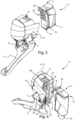
- FIGs. 1-4 an illustrative bicycle equipment 1 is shown, provided with an electric power supply unit 2.
- the bicycle equipment 1 is a front derailleur 3 comprising a support body 4 configured to be attached to a bicycle frame, a chain guide 5 and a pair of connecting arms 6, 7 extended between the support body 4 and the chain guide 5, forming a plurality of mutually movable components and in particular an articulated parallelogram.
- the pair of connecting arms comprises a proximal connecting arm 6 and a distal connecting arm 7.
- proximal and distal refer to the mounted condition of the derailleur on the bicycle. In particular, "proximal” is used to mean closer to the frame, and adjective “distal” is used to mean farther from the frame.
- the derailleur 3 comprises a geared motor (not visible).
- the geared motor may be purely electric or electronic, when the derailleur 3 also includes a data processing system for controlling the geared motor and any other electric/electronic components of the derailleur 3, for example comprising one or more components borne by one or more printed circuit boards or PCB.
- the geared motor may also comprise a motor not coupled with any speed reducer.
- the geared motor controls the mutual motion between chain guide 5 and support body 4, in particular determines the aperture and closure of the articulated parallelogram, and therefore the displacement of the chain guide 5 in the direction of the bottom bracket spindle, so as to bring the transmission chain or belt into engagement with a predetermined toothed wheel or chainring of the crankset.
- the geared motor is for example housed in the support body 4 and controls the rotation of one of the connecting arms 6, 7 (in the case shown, the proximal connecting arm 6) about a pivot axis thereof to the support body 4.
- the support body 4 may be attached to the frame through a screw in screw engagement with the threaded hole 8.
- the electric power supply unit 2 comprises one or more secondary cells and may have a hermetic case housing said one or more secondary cells.
- the electric power supply unit 2 may also include at least one printed circuit board or PCB (cf. the PCB 49 in FIG. 12 ) bearing electronic components controlling the electric power supply unit 2, housed in the hermetic case.
- the electric power supply unit 2 may therefore be a so-called smart battery.
- the electric power supply unit 2 is removably attached to the derailleur 3 and is shown in the detached condition in FIGs. 3-4 .
- a component of the derailleur 1 the support body 4 in the case shown, has a seat 9 for the electric power supply unit 2.
- the component having the seat for the electric power supply unit is not necessarily the support body 4 and therefore hereinbelow the component provided with the seat 9 will be referred to as component 10.
- At least one clamping device 11 of the electric power supply unit 2 to the component 10 in the seated state of the electric power supply unit 2 is provided for, wherein the electric power supply unit 2 is arranged in the seat 9.
- the electric power supply unit 2 is firmly held on the derailleur 3 despite the vibrations and the shocks to which it is subject during the travel of the bicycle.
- the clamping device 11 is supported by the electric power supply unit 2.
- the clamping device 11 is pivotally supported about a first geometric axis 12 stationary with respect to the electric power supply unit 2 supporting it, as well as about a second geometric axis 13.
- the second geometric axis 13 is parallel to the first geometric axis 12, is pivotal about the first geometric axis 12, and is not translatable with respect to the first geometric axis 12.
- the clamping device 11 comprises a substantially flat and elongate or band-shaped main body 14, and the geometric axes 12, 13 extend along the transverse direction of the main body 14.
- the second geometric axis 13 extends in proximity to a first longitudinal end 15 of the main body 14.
- a seat 16 FIG. 9 may be made to favour the lifting of such first longitudinal end 15 with one or more fingers during unlocking of the clamping device 11.
- the first geometric axis 12 is in a position corresponding to an intermediate position of the main body 14 in the clamped status of the clamping device 11.
- the two geometric axes 12, 13 of rotation of the clamping device 11 may for example be defined by two opposed sides 21, 22 of a quadrangular ring 20, as shown in FIGs. 9-11 wherein the quadrangular ring 20 is shown alone ( FIG. 10 ) and, in dotted line, in the clamping device 11, coupled with its main body 14 ( FIG. 9 ), and in the condition coupled with the electric power supply unit 2 ( FIG. 11 ).
- the first side 21 of the quadrangular ring 20 is split and extends in a pivoting seat 23 formed by a through hole or by two coaxial blind holes, made for example in a protrusion 24 of the electric power supply unit 2.
- the second side 22 of the quadrangular ring 20 extends in a pivoting seat 25 which comprises a cylindrical undercut cavity, made for example in a protrusion 26 of the clamping device 11. If necessary, a slit 27 may be provided for on the clamping device 11 close to an end of the pivoting seat 25 for slidingly inserting the second side 22 of the quadrangular ring 20 thereinto.
- the quadrangular split ring 20 has sufficient stiffness to withstand the traction in the clamped status of the clamping device 11, as better discussed hereinbelow. It is therefore a rigid member.
- the quadrangular split ring 20 has, on the other hand, sufficiently low stiffness to allow spreading of the two portions of its first split side 21 for insertion thereof in the two blind holes or in the two ends of the through hole embodying the pivoting seat 23 during assembly.
- the pivoting seats 23, 25 are formed on facing faces, in the clamped status of the clamping device 11, of the electric power supply unit 2 and of the clamping device 11.
- the arrangement of the sides 21, 22 and of the respective pivoting seats 23, 25 might be inverted with respect to what is shown. Furthermore, the quadrangular ring 20 might not be split, for example providing for two pivoting seats each comprising a cylindrical undercut cavity.
- the quadrangular ring 20 might be replaced by another member having the above mentioned characteristics of stiffness, for example a rigid plate or bar articulated at its ends in any suitable manner.
- the clamping device 11 that as mentioned in the case shown is supported by the electric power supply unit 2, is configured to interact with the component 10 so as to firmly retain the electric power supply unit 2 thereon in the clamped status of the clamping device 11 itself.
- the clamping device 11 has a retainable member 30 associated with a retainer member 31 provided on the component 10.
- the retainer member 31 is in the form of a protrusion and the retainable member 30 is in the form of a cavity sized to accommodate the retainer member 31.
- the cavity is shown as a through one, but alternatively it could be blind.
- the retainable member 30 is provided for in proximity to a second longitudinal end 17 of the main body 14, opposed to the first longitudinal end 15.
- FIGs. 5-8 it is seen that the rotation of the clamping device 11 in a first direction A about the first axis 12 (counterclockwise rotation in the drawings) and in the second direction B (clockwise rotation in the drawings) opposed to the first direction A about the second axis 13 allows the retainable member 30 of the clamping device 11 to be brought beyond the retainer member 31, herein provided on the component 10, during clamping and unclamping.
- the retainable member 30 "climbs over" the retainer member 31.
- Arrows A, B are shown in FIG. 6 , representing the movement which intervened between the position of FIG. 5 and that of FIG. 6 .
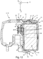
- the retainable member 30 is urged against the retainer member 31 in the positive direction of axis Y shown in FIG. 12 , which represents in general an oriented removal direction of the electric power supply unit 2 from the component 10, which is orthogonal to the direction defined by the rotation axes 12, 13 or axis X shown in FIG. 12 (entering the drawing plane).
- the retainable member 30 and the retainer member 31 embody a coupling effective in retaining the electric power supply unit 2 in the oriented removal direction or axis Y.
- the retainable member 30 and the retainer member 31 have respective surfaces 32, 33 mutually abutting in the clamped status of the clamping device 11.
- the surface 32 of the retainable member 30 exerts a pushing force on the surface 33 of the retainer member 31, which acts as an abutment or limiter.
- a second condition occurring in the clamped status of the clamping device 11 is that, looking in the oriented removal direction or axis Y, the first geometric axis 12 is interposed between the second geometric axis 13 (at the right thereof in the drawing) and the retainable and retainer members 30, 31 (at the left thereof in the drawing).
- a third condition occurring in the clamped status of the clamping device 11 is that the second geometric axis 13 is closer to the electric power supply unit 2 with respect to the first geometric axis 12 in a third direction, or axis Z shown in FIG. 12 , orthogonal to the direction of the rotation axes or axis X and to the oriented removal direction or axis Y.
- the second geometric axis 13 is thus lower than the first geometric axis 12.
- the possibility of rotation of the clamping device 11 about the two parallel rotation axes 12, 13 thus allows the retainable member 30 to be brought into or out of engagement with the associated retainer member 31, locking and unlocking the clamping device 11 through a simple movement.
- the clamping device 11 is simple and of low weight, a factor that is of high relevance at least in the field of racing bicycles.
- the absence of complex mechanisms and of springs makes the clamping device 11 particularly strong and reliable, capable of remaining operative also in the conditions of dirt and humidity to which a bicycle is subject.
- the retainer member 31 is in the form of a protrusion and the retainable member 30 is in the form of a cavity sized to accommodate the retainer member 31.
- the cavity or retainable member 30 is oversized with respect to the protrusion or retainer member 31, so as to allow insertion thereof without relative sliding between said two surfaces 32, 33, and indeed in such a direction that there is a gap therebetween during the locking movement of the clamping device 11.
- Said surfaces 32, 33 may be, as shown, slanted with respect to the removal direction or axis Y, so that the retainable member 30 and the retainer member 31 embody a "hook-like" coupling.
- the surfaces 32, 33 extend from top left to bottom right; in general the surfaces 32, 33 may have a first edge (bottom in FIG. 12 ) that is comparatively close to the first axis 12 in the removal direction (axis Y) and to the electric power supply unit 2 in the third direction (axis Z), and a second edge (top in FIG. 12 ) opposed to the first edge which is comparatively far from the first axis 12 in the removal direction (axis Y) and from the electric power supply unit 2 in the third direction (axis Z).
- the cavity defining (in the case shown) the retainable member 30 may not be oversized with respect to the protrusion defining (in the case shown) the retainer member 31, so that the retainable member 30 and the retainer member 31 embody a coupling effective also in retaining the electric power supply unit 2 in the direction of the rotation axes 12, 13 (axis X) in the clamped status of the clamping device 11.
- the seat 9 has a first surface 40 ( FIG. 4 ) extending substantially orthogonal to the oriented removal direction (axis Y), which defines the stop position of the electric power supply unit 2, in the opposed oriented direction, of approach.
- the region 41 of the electric power supply unit 2 involved by the clamping device 11 is intended to be higher in the condition wherein the derailleur 3 is mounted on the bicycle and with the bicycle in the condition of straight travel on level ground; in its opposed region 42, the electric power supply unit 2 is supported and held by the seat 9.
- the seat 9 is in particular configured to retain said opposed region 42 of the electric power supply unit 2 against removal from the component 10 in the third direction (axis Z) downwards, in said condition of bicycle in straight travel on level ground and in FIG. 12 .
- the seat 9 has, to that end, a lower bracket 43 onto which the electric power supply unit 2 rests.
- the lower bracket 43 is provided with a cavity 44 - shown as a through one, but which might also be blind - configured to accommodate a protrusion 45 ( FIG. 3 ) provided on said opposed region 42 of the electric power supply unit 2.
- the cavity 44 is for example oversized with respect to the protrusion 45 in the removal direction (axis Y) but not in the direction of the rotation axes (axis X).
- the seat 9 is configured to retain said opposed region 42 of the electric power supply unit 2 against removal from the component 10 in the direction of the rotation axes (axis X), still allowing the seating of the electric power supply unit 2 without particular friction, possibly with a roto-translational movement as manifest from a comparison of FIGs. 5 and 6 .
- the seat 9 shown has a wall 46 protruding in the oriented removal direction or axis Y, retaining the electric power supply unit 2 against removal in the direction of the rotation axes 12, 13 (axis X).
- the wall 46 is on the distal side of the derailleur 3, so as to protect the electric power supply unit 2 also against shocks.
- the seat 9 may be shaped in a manner also appreciably different from what is shown, and support and retain the electric power supply unit 2 in a different manner and/or not in all the oriented directions mentioned above.
- a clamping device analogous to the clamping device 11 may be provided for at said region 42 of the electric power supply unit 2 substantially opposed to the region 41 involved by the clamping device 11, and/or at other regions of the electric power supply unit 2, for example at the distal face and/or of the proximal face of the derailleur 3.
- the electric power supply unit 2 shown is substantially in the shape of a rectangular parallelepiped, but the shape of the electric power supply unit 2 may differ even appreciably from that shown.
- the electric power supply unit 2 may be in the shape of an oblique parallelepiped, or it may comprise one or more concave or convex faces (or regions thereof).
- the component 10 shown has a shape generically of rectangular parallelepiped shape, and the seat 9 for the electric power supply unit 2 involves, for example, only part of a face 47 thereof, as evident in FIGs. 2 and 4 , roughly a half thereof.
- the remaining half of said face 47 of the component 10 and a face 48 of the electric power supply unit 2 adjacent thereto (proximal face of the electric power supply unit 2 in the case shown) turn out to be substantially orthogonal, so that the component 10 with the electric power supply unit 2 seated has a shape generally like a straight prism with L-shaped base.
- the seat 9 is for example side by side with the attachment seat of the main body 4 to the seat post, bearing the threaded hole 8, so that the derailleur 3 with the electric power supply unit 2 seated may partly surround the seat post.
- the seat post then protects the electric power supply unit 2 against shocks, besides contributing to retain it against displacements in the direction of the rotation axes (axis X).
- the seat 9 and the electric power supply unit 2 have matching electric contacts 80, 81 that establish electric connection in the seated state of the electric power supply unit 2.
- four pairs of matching electric contacts 80, 81 are provided for, among which two pairs are connected to the negative pole (ground) and to the positive pole (power supply) of the secondary cells of the electric power supply unit 2 and are provided to lead the power supply voltage from the electric power supply unit 2 to the user(s) provided for in the component 10, for example to the geared motor, and possibly for recharging the secondary cells when the electric power supply unit 2 is not seated.
- the other two pairs of matching electric contacts 80, 81 may be used for example for full duplex series connection between the equipment 1 and the electric power supply unit 2, when it is of the smart battery type, provided with electronic components borne for example by the PCB 49.
- From the equipment 1 to the electric power supply unit 2, for example a serial number thereof, a firmware update program, a request to communicate said data, etc. may be communicated.
- a different number of pairs of matching electric contacts 80, 81 and/or a different type and communication mode may however be provided for.
- the matching electric contacts 80, 81 are provided on the first surface 40 of the seat 9 and on the surface 50 paired thereto of the electric power supply unit 2, extending substantially orthogonal to the removal direction Y.
- the matching electric contacts 80, 81 may be provided on other surfaces of the seat 9 and of the electric power supply unit 2, that enter into mechanical contact when the electric power supply unit 2 is seated, for example on the bracket 43 (for example by providing for the same to protrude more than shown) or on the protruding wall 46 and on the respectively paired surfaces of the electric power supply unit 2.
- the matching electric contacts 80, 81 may be arranged in a protrusion 83 and a recess 84 of complementary shapes.
- the protrusion 83 is made in the electric power supply unit 2 and the recess 84 is made in the component 20, but they might be inverted.
- the protrusion 83 may have a peripheral groove 85 ( FIG. 12 ), a hermetic seal 86 ( FIG. 12 , 15 ) extending in the peripheral groove 85.
- the "male” electric contact, of the component 10 in the case shown by way of an example, may be of the pogo pin type.
- a pogo pin - see the pogo-pins 90 of which also a section is schematically shown in FIG. 14 - comprises a plunger 91 sliding in a blind barrel 92; the plunger 91 is forced in the position protruding from the barrel 92, outwards, by a helical spring 93.
- the pogo pin contacts are for example gathered on a printed circuit board or PCB 94 and the barrels 92 extend through parallel through holes 95 of an electrically insulating support 96 that may also serve as a hermetic seal.
- the pogo-pin may be directly tinned to the respective electrical conductors.
- the matching contact 100 ( FIG. 16 ) of a pogo pin comprises a plane or concave plate 101 contacting the plunger 91 of the pogo pin 90.
- the matching contacts 100 are for example gathered on a printed circuit board or PCB 102 and extend through parallel through holes 103 of an electrically insulating support 104 that may also serve as a hermetic seal.
- the plate 101 may be directly embodied by a plated pad on the PCB 102.
- the ground electric contact 105 (“female” or matching contact 100 of the pogo pin 90) may be more outcropping than the other electric contacts of the electric power supply unit 2 (in the illustrative case shown).
- the electric contacts of the electric power supply unit 2 are arranged in two overlapping rows, and the more outcropping ground electric contact 105 is in the bottom row. In this manner, it is the first to enter into mechanical and electric contact with the respective pogo pin 97 during the roto-translational movement of seating of the electric power supply unit 2 described above, so as to protect the electronics by stabilizing the reference voltage level before the establishment of the remaining electrical connections.
- clamping device 11 is shown supported by the electric power supply unit 2 and interacting with the retainer member 31 provided on the component 10, those skilled in the art will understand, in the light of the previous description, that a dual configuration is possible, wherein the clamping device 11 is borne by the component 10 and the retainer member 31 is provided on the electric power supply unit 2.
- the retainable member 30 may be in the shape of a protrusion and the retainer member 31 may be in the shape of a cavity sized to accommodate the retainable member 30.
- the retainable member 30 and the retaining member 31 may comprise a plurality of protrusions and cavities, paired hooks, a hook and a loop, and in general they may adopt any configuration suitable to perform one or more of the functions described above.
- the derailleur 3 may have a shape even considerably different from that shown and/or additional components, not shown for the sake of simplicity.
- the geared motor and the seat 9 are both arranged in the support body 4.
- the geared motor may be housed in a second component of the derailleur 3 or in general of the bicycle equipment 1, different from the component 10 preselected for the seat 9, an electric connection being provided for, extended between the contacts of the seat 9 and the second component.
- the secondary cells of the electric power supply unit 2 may be recharged while the electric power supply unit 2 is on board of the bicycle, by providing for suitable recharging connectors, and/or the electric power supply unit 2 may be recharged in a recharge cradle after having been detached from the equipment 1, possibly exploiting the same electric contacts 81.
- FIGs. 17 and 18 show a rear derailleur 110, wherein the electric power supply unit 2 is attached and partly detached, respectively.
- Like numbers are used for members similar or corresponding to those used for the front derailleur 3.
- the displacement of the chain guide 5 has at least one displacement component in the direction of the axis of the group of toothed wheels associated with the hub of the rear wheel or "sprocket assembly", so as to bring the transmission chain or belt into engagement with a predetermined toothed wheel or sprocket of the sprocket assembly.
- the component 10 having the seat for removable attachment of the electric power supply unit 2 is the proximal connecting arm 6 and the geared motor is, for example, supported by the top body 4, but also in this case different locations of the electric power supply unit 2 and of the geared motor are possible.
Landscapes
- Engineering & Computer Science (AREA)
- Mechanical Engineering (AREA)
- Chemical & Material Sciences (AREA)
- Combustion & Propulsion (AREA)
- Transportation (AREA)
- Power Engineering (AREA)
- Electric Propulsion And Braking For Vehicles (AREA)
- Battery Mounting, Suspending (AREA)
- Arrangement Or Mounting Of Propulsion Units For Vehicles (AREA)
- Axle Suspensions And Sidecars For Cycles (AREA)
- Steering Devices For Bicycles And Motorcycles (AREA)
- Motorcycle And Bicycle Frame (AREA)
Applications Claiming Priority (1)
| Application Number | Priority Date | Filing Date | Title |
|---|---|---|---|
| IT102021000024716A IT202100024716A1 (it) | 2021-09-28 | 2021-09-28 | Equipaggiamento di bicicletta dotato di unita’ di alimentazione elettrica |
Publications (2)
| Publication Number | Publication Date |
|---|---|
| EP4155178A1 true EP4155178A1 (de) | 2023-03-29 |
| EP4155178B1 EP4155178B1 (de) | 2026-01-21 |
Family
ID=78771074
Family Applications (1)
| Application Number | Title | Priority Date | Filing Date |
|---|---|---|---|
| EP22197990.9A Active EP4155178B1 (de) | 2021-09-28 | 2022-09-27 | Klemmvorrichtung einer stromversorgungseinheit von fahrradausrüstung |
Country Status (5)
| Country | Link |
|---|---|
| US (1) | US12403975B2 (de) |
| EP (1) | EP4155178B1 (de) |
| CN (1) | CN115871828A (de) |
| IT (1) | IT202100024716A1 (de) |
| TW (1) | TW202323121A (de) |
Cited By (1)
| Publication number | Priority date | Publication date | Assignee | Title |
|---|---|---|---|---|
| EP4725817A1 (de) | 2024-10-08 | 2026-04-15 | Campagnolo S.r.l. | Elektrisches fahrradvorrichtung |
Families Citing this family (5)
| Publication number | Priority date | Publication date | Assignee | Title |
|---|---|---|---|---|
| US9394030B2 (en) * | 2012-09-27 | 2016-07-19 | Sram, Llc | Rear derailleur |
| US11745824B2 (en) * | 2020-11-06 | 2023-09-05 | Sram, Llc | Control device for a bicycle |
| IT202100024716A1 (it) * | 2021-09-28 | 2023-03-28 | Campagnolo Srl | Equipaggiamento di bicicletta dotato di unita’ di alimentazione elettrica |
| US12116085B1 (en) | 2023-10-20 | 2024-10-15 | Shimano Inc. | Component for human-powered vehicle |
| CN117134142B (zh) * | 2023-10-26 | 2024-02-27 | 安费诺汽车连接系统(常州)有限公司 | 充电座分体式端子安装结构 |
Citations (9)
| Publication number | Priority date | Publication date | Assignee | Title |
|---|---|---|---|---|
| EP2112060A2 (de) * | 2008-04-21 | 2009-10-28 | Shimano, Inc. | Batteriehalter für ein Fahrrad |
| US20150022717A1 (en) * | 2013-07-19 | 2015-01-22 | Gopro, Inc. | Simplified Draw Latch with Bent Wireform Mid-Linkage |
| US20150380709A1 (en) * | 2014-06-25 | 2015-12-31 | Mizco International Inc. | System and method for increasing operational time of an electronic device |
| US20170078537A1 (en) * | 2015-09-11 | 2017-03-16 | Avant Technology, Inc. | Camera Case with Removable Carrier, Filter Receiver, External Battery and Supplemental Memory Storage |
| US20180257736A1 (en) * | 2017-03-08 | 2018-09-13 | Shimano Inc. | Bicycle electric device and bicycle wireless control system |
| US20190100279A1 (en) * | 2017-10-02 | 2019-04-04 | Sram, Llc | Bicycle rear derailleur |
| TWM591071U (zh) * | 2019-09-25 | 2020-02-21 | 彥豪金屬工業股份有限公司 | 自行車變速器及電池固定組件 |
| DE102019106626A1 (de) * | 2019-03-15 | 2020-09-17 | Shimano Inc. | Stromversorgungsadapter für fahrradkomponente und fahrradkomponentenanordnung |
| EP3873797A1 (de) * | 2018-11-02 | 2021-09-08 | Newcycle Inc. | Klappbares fahrzeug |
Family Cites Families (9)
| Publication number | Priority date | Publication date | Assignee | Title |
|---|---|---|---|---|
| JP2007203954A (ja) * | 2006-02-03 | 2007-08-16 | Shimano Inc | 自転車用ディレーラ |
| US8066597B2 (en) * | 2007-03-15 | 2011-11-29 | Shimano, Inc. | Electrically operated derailleur with force overload protection |
| US9399499B2 (en) * | 2011-06-29 | 2016-07-26 | Shimano Inc. | Bicycle battery holder |
| US9394030B2 (en) * | 2012-09-27 | 2016-07-19 | Sram, Llc | Rear derailleur |
| US9890838B2 (en) * | 2012-10-18 | 2018-02-13 | Sram, Llc | Front gear changer |
| US9469378B2 (en) * | 2014-09-17 | 2016-10-18 | Shimano Inc. | Bicycle derailleur |
| US10981625B2 (en) * | 2017-10-02 | 2021-04-20 | Sram, Llc | Bicycle rear derailleur |
| IT202100024770A1 (it) * | 2021-09-28 | 2023-03-28 | Campagnolo Srl | Equipaggiamento di bicicletta dotato di unita’ di alimentazione elettrica |
| IT202100024716A1 (it) * | 2021-09-28 | 2023-03-28 | Campagnolo Srl | Equipaggiamento di bicicletta dotato di unita’ di alimentazione elettrica |
-
2021
- 2021-09-28 IT IT102021000024716A patent/IT202100024716A1/it unknown
-
2022
- 2022-09-20 TW TW111135491A patent/TW202323121A/zh unknown
- 2022-09-26 CN CN202211172386.5A patent/CN115871828A/zh active Pending
- 2022-09-27 EP EP22197990.9A patent/EP4155178B1/de active Active
- 2022-09-27 US US17/953,984 patent/US12403975B2/en active Active
Patent Citations (9)
| Publication number | Priority date | Publication date | Assignee | Title |
|---|---|---|---|---|
| EP2112060A2 (de) * | 2008-04-21 | 2009-10-28 | Shimano, Inc. | Batteriehalter für ein Fahrrad |
| US20150022717A1 (en) * | 2013-07-19 | 2015-01-22 | Gopro, Inc. | Simplified Draw Latch with Bent Wireform Mid-Linkage |
| US20150380709A1 (en) * | 2014-06-25 | 2015-12-31 | Mizco International Inc. | System and method for increasing operational time of an electronic device |
| US20170078537A1 (en) * | 2015-09-11 | 2017-03-16 | Avant Technology, Inc. | Camera Case with Removable Carrier, Filter Receiver, External Battery and Supplemental Memory Storage |
| US20180257736A1 (en) * | 2017-03-08 | 2018-09-13 | Shimano Inc. | Bicycle electric device and bicycle wireless control system |
| US20190100279A1 (en) * | 2017-10-02 | 2019-04-04 | Sram, Llc | Bicycle rear derailleur |
| EP3873797A1 (de) * | 2018-11-02 | 2021-09-08 | Newcycle Inc. | Klappbares fahrzeug |
| DE102019106626A1 (de) * | 2019-03-15 | 2020-09-17 | Shimano Inc. | Stromversorgungsadapter für fahrradkomponente und fahrradkomponentenanordnung |
| TWM591071U (zh) * | 2019-09-25 | 2020-02-21 | 彥豪金屬工業股份有限公司 | 自行車變速器及電池固定組件 |
Cited By (1)
| Publication number | Priority date | Publication date | Assignee | Title |
|---|---|---|---|---|
| EP4725817A1 (de) | 2024-10-08 | 2026-04-15 | Campagnolo S.r.l. | Elektrisches fahrradvorrichtung |
Also Published As
| Publication number | Publication date |
|---|---|
| US12403975B2 (en) | 2025-09-02 |
| TW202323121A (zh) | 2023-06-16 |
| EP4155178B1 (de) | 2026-01-21 |
| IT202100024716A1 (it) | 2023-03-28 |
| CN115871828A (zh) | 2023-03-31 |
| US20230101681A1 (en) | 2023-03-30 |
Similar Documents
| Publication | Publication Date | Title |
|---|---|---|
| EP4155178B1 (de) | Klemmvorrichtung einer stromversorgungseinheit von fahrradausrüstung | |
| US11919594B2 (en) | Bicycle equipment provided with an electric power supply unit | |
| US7411307B2 (en) | Apparatus for providing electrical signals to bicycle components | |
| US20240055674A1 (en) | Battery pack, electric device using battery pack, and electric device system | |
| CN1168157C (zh) | 用于电动工具的电源组件充电系统及其使用方法 | |
| US7100932B2 (en) | Integrated control and power unit for use aboard a bicycle | |
| US11807338B2 (en) | Drive unit for human-powered vehicle and battery holding device of human-powered vehicle | |
| EP1394031B1 (de) | Apparat zum Verkabeln der Fahrradelektrik | |
| CN1158012A (zh) | 电池组件 | |
| US20190259985A1 (en) | Battery pack, electrical device using battery pack, and electrical device system | |
| CN109591952A (zh) | 自行车后拨链器 | |
| CN105936323A (zh) | 电自行车后拨链器 | |
| US12537348B2 (en) | Bicycle equipment provided with an electric power supply unit | |
| TWI474944B (zh) | Straddle type electric vehicle | |
| CN211958036U (zh) | 接插件、电池组件及电动自行车 | |
| US12573707B2 (en) | Electrical apparatus | |
| EP4379926A2 (de) | Batteriezellenträger für batteriepack | |
| WO2021188041A1 (en) | Swappable battery pack | |
| JP7833165B2 (ja) | 電動自転車のバッテリー装置および電動折り畳み自転車 | |
| CN223031194U (zh) | 一种电子变速器 | |
| JP2024129919A (ja) | 保持装置 | |
| US20230318329A1 (en) | Electrical apparatus and apparatus system | |
| TW202400453A (zh) | 自行車組件及用於自行車組件的電池 | |
| WO2024190664A1 (ja) | 保持装置 | |
| WO2025004060A1 (en) | A protective cap for a battery connector of a vehicle |
Legal Events
| Date | Code | Title | Description |
|---|---|---|---|
| PUAI | Public reference made under article 153(3) epc to a published international application that has entered the european phase |
Free format text: ORIGINAL CODE: 0009012 |
|
| STAA | Information on the status of an ep patent application or granted ep patent |
Free format text: STATUS: THE APPLICATION HAS BEEN PUBLISHED |
|
| AK | Designated contracting states |
Kind code of ref document: A1 Designated state(s): AL AT BE BG CH CY CZ DE DK EE ES FI FR GB GR HR HU IE IS IT LI LT LU LV MC MK MT NL NO PL PT RO RS SE SI SK SM TR |
|
| P01 | Opt-out of the competence of the unified patent court (upc) registered |
Effective date: 20230516 |
|
| STAA | Information on the status of an ep patent application or granted ep patent |
Free format text: STATUS: REQUEST FOR EXAMINATION WAS MADE |
|
| 17P | Request for examination filed |
Effective date: 20230905 |
|
| RBV | Designated contracting states (corrected) |
Designated state(s): AL AT BE BG CH CY CZ DE DK EE ES FI FR GB GR HR HU IE IS IT LI LT LU LV MC MK MT NL NO PL PT RO RS SE SI SK SM TR |
|
| GRAP | Despatch of communication of intention to grant a patent |
Free format text: ORIGINAL CODE: EPIDOSNIGR1 |
|
| STAA | Information on the status of an ep patent application or granted ep patent |
Free format text: STATUS: GRANT OF PATENT IS INTENDED |
|
| INTG | Intention to grant announced |
Effective date: 20250919 |
|
| GRAS | Grant fee paid |
Free format text: ORIGINAL CODE: EPIDOSNIGR3 |
|
| GRAA | (expected) grant |
Free format text: ORIGINAL CODE: 0009210 |
|
| STAA | Information on the status of an ep patent application or granted ep patent |
Free format text: STATUS: THE PATENT HAS BEEN GRANTED |
|
| AK | Designated contracting states |
Kind code of ref document: B1 Designated state(s): AL AT BE BG CH CY CZ DE DK EE ES FI FR GB GR HR HU IE IS IT LI LT LU LV MC MK MT NL NO PL PT RO RS SE SI SK SM TR |
|
| REG | Reference to a national code |
Ref country code: CH Ref legal event code: F10 Free format text: ST27 STATUS EVENT CODE: U-0-0-F10-F00 (AS PROVIDED BY THE NATIONAL OFFICE) Effective date: 20260121 |
|
| REG | Reference to a national code |
Ref country code: DE Ref legal event code: R096 Ref document number: 602022028764 Country of ref document: DE |
|
| REG | Reference to a national code |
Ref country code: IE Ref legal event code: FG4D |