EP4155497A1 - Fenster - Google Patents
Fenster Download PDFInfo
- Publication number
- EP4155497A1 EP4155497A1 EP22197766.3A EP22197766A EP4155497A1 EP 4155497 A1 EP4155497 A1 EP 4155497A1 EP 22197766 A EP22197766 A EP 22197766A EP 4155497 A1 EP4155497 A1 EP 4155497A1
- Authority
- EP
- European Patent Office
- Prior art keywords
- stop
- wing
- window
- frame
- bearing
- Prior art date
- Legal status (The legal status is an assumption and is not a legal conclusion. Google has not performed a legal analysis and makes no representation as to the accuracy of the status listed.)
- Granted
Links
Images


Classifications
-
- E—FIXED CONSTRUCTIONS
- E05—LOCKS; KEYS; WINDOW OR DOOR FITTINGS; SAFES
- E05F—DEVICES FOR MOVING WINGS INTO OPEN OR CLOSED POSITION; CHECKS FOR WINGS; WING FITTINGS NOT OTHERWISE PROVIDED FOR, CONCERNED WITH THE FUNCTIONING OF THE WING
- E05F5/00—Braking devices, e.g. checks; Stops; Buffers
- E05F5/06—Buffers or stops limiting opening of swinging wings, e.g. floor or wall stops
-
- E—FIXED CONSTRUCTIONS
- E05—LOCKS; KEYS; WINDOW OR DOOR FITTINGS; SAFES
- E05B—LOCKS; ACCESSORIES THEREFOR; HANDCUFFS
- E05B15/00—Other details of locks; Parts for engagement by bolts of fastening devices
- E05B15/0006—Devices for aligning wing and frame; Anti-rattling devices
-
- E—FIXED CONSTRUCTIONS
- E05—LOCKS; KEYS; WINDOW OR DOOR FITTINGS; SAFES
- E05C—BOLTS OR FASTENING DEVICES FOR WINGS, SPECIALLY FOR DOORS OR WINDOWS
- E05C7/00—Fastening devices specially adapted for two wings
- E05C7/04—Fastening devices specially adapted for two wings for wings which abut when closed
-
- E—FIXED CONSTRUCTIONS
- E05—LOCKS; KEYS; WINDOW OR DOOR FITTINGS; SAFES
- E05C—BOLTS OR FASTENING DEVICES FOR WINGS, SPECIALLY FOR DOORS OR WINDOWS
- E05C9/00—Arrangements of simultaneously actuated bolts or other securing devices at well-separated positions on the same wing
- E05C9/18—Details of fastening means or of fixed retaining means for the ends of bars
- E05C9/1825—Fastening means
- E05C9/1833—Fastening means performing sliding movements
- E05C9/185—Fastening means performing sliding movements parallel with actuating bar
-
- E—FIXED CONSTRUCTIONS
- E06—DOORS, WINDOWS, SHUTTERS, OR ROLLER BLINDS IN GENERAL; LADDERS
- E06B—FIXED OR MOVABLE CLOSURES FOR OPENINGS IN BUILDINGS, VEHICLES, FENCES OR LIKE ENCLOSURES IN GENERAL, e.g. DOORS, WINDOWS, BLINDS, GATES
- E06B1/00—Border constructions of openings in walls, floors, or ceilings; Frames to be rigidly mounted in such openings
- E06B1/04—Frames for doors, windows, or the like to be fixed in openings
- E06B1/12—Metal frames
- E06B1/14—Metal frames of special cross-section not used
- E06B1/16—Hollow frames
-
- E—FIXED CONSTRUCTIONS
- E06—DOORS, WINDOWS, SHUTTERS, OR ROLLER BLINDS IN GENERAL; LADDERS
- E06B—FIXED OR MOVABLE CLOSURES FOR OPENINGS IN BUILDINGS, VEHICLES, FENCES OR LIKE ENCLOSURES IN GENERAL, e.g. DOORS, WINDOWS, BLINDS, GATES
- E06B3/00—Window sashes, door leaves, or like elements for closing wall or like openings; Layout of fixed or moving closures, e.g. windows in wall or like openings; Features of rigidly-mounted outer frames relating to the mounting of wing frames
- E06B3/04—Wing frames not characterised by the manner of movement
- E06B3/06—Single frames
- E06B3/08—Constructions depending on the use of specified materials
- E06B3/12—Constructions depending on the use of specified materials of metal
- E06B3/14—Constructions depending on the use of specified materials of metal of special cross-section
- E06B3/16—Hollow frames of special construction, e.g. made of folded sheet metal or of two or more section parts connected together
-
- E—FIXED CONSTRUCTIONS
- E06—DOORS, WINDOWS, SHUTTERS, OR ROLLER BLINDS IN GENERAL; LADDERS
- E06B—FIXED OR MOVABLE CLOSURES FOR OPENINGS IN BUILDINGS, VEHICLES, FENCES OR LIKE ENCLOSURES IN GENERAL, e.g. DOORS, WINDOWS, BLINDS, GATES
- E06B3/00—Window sashes, door leaves, or like elements for closing wall or like openings; Layout of fixed or moving closures, e.g. windows in wall or like openings; Features of rigidly-mounted outer frames relating to the mounting of wing frames
- E06B3/04—Wing frames not characterised by the manner of movement
- E06B3/263—Frames with special provision for insulation
- E06B3/26301—Frames with special provision for insulation with prefabricated insulating strips between two metal section members
- E06B3/26303—Frames with special provision for insulation with prefabricated insulating strips between two metal section members with thin strips, e.g. defining a hollow space between the metal section members
-
- E—FIXED CONSTRUCTIONS
- E06—DOORS, WINDOWS, SHUTTERS, OR ROLLER BLINDS IN GENERAL; LADDERS
- E06B—FIXED OR MOVABLE CLOSURES FOR OPENINGS IN BUILDINGS, VEHICLES, FENCES OR LIKE ENCLOSURES IN GENERAL, e.g. DOORS, WINDOWS, BLINDS, GATES
- E06B3/00—Window sashes, door leaves, or like elements for closing wall or like openings; Layout of fixed or moving closures, e.g. windows in wall or like openings; Features of rigidly-mounted outer frames relating to the mounting of wing frames
- E06B3/32—Arrangements of wings characterised by the manner of movement; Arrangements of movable wings in openings; Features of wings or frames relating solely to the manner of movement of the wing
- E06B3/34—Arrangements of wings characterised by the manner of movement; Arrangements of movable wings in openings; Features of wings or frames relating solely to the manner of movement of the wing with only one kind of movement
- E06B3/36—Arrangements of wings characterised by the manner of movement; Arrangements of movable wings in openings; Features of wings or frames relating solely to the manner of movement of the wing with only one kind of movement with a single vertical axis of rotation at one side of the opening, or swinging through the opening
- E06B3/362—Double winged doors or windows
-
- E—FIXED CONSTRUCTIONS
- E05—LOCKS; KEYS; WINDOW OR DOOR FITTINGS; SAFES
- E05Y—INDEXING SCHEME ASSOCIATED WITH SUBCLASSES E05D AND E05F, RELATING TO CONSTRUCTION ELEMENTS, ELECTRIC CONTROL, POWER SUPPLY, POWER SIGNAL OR TRANSMISSION, USER INTERFACES, MOUNTING OR COUPLING, DETAILS, ACCESSORIES, AUXILIARY OPERATIONS NOT OTHERWISE PROVIDED FOR, APPLICATION THEREOF
- E05Y2201/00—Constructional elements; Accessories therefor
- E05Y2201/20—Brakes; Disengaging means; Holders; Stops; Valves; Accessories therefor
- E05Y2201/224—Stops
-
- E—FIXED CONSTRUCTIONS
- E05—LOCKS; KEYS; WINDOW OR DOOR FITTINGS; SAFES
- E05Y—INDEXING SCHEME ASSOCIATED WITH SUBCLASSES E05D AND E05F, RELATING TO CONSTRUCTION ELEMENTS, ELECTRIC CONTROL, POWER SUPPLY, POWER SIGNAL OR TRANSMISSION, USER INTERFACES, MOUNTING OR COUPLING, DETAILS, ACCESSORIES, AUXILIARY OPERATIONS NOT OTHERWISE PROVIDED FOR, APPLICATION THEREOF
- E05Y2201/00—Constructional elements; Accessories therefor
- E05Y2201/40—Motors; Magnets; Springs; Weights; Accessories therefor
- E05Y2201/46—Magnets
-
- E—FIXED CONSTRUCTIONS
- E05—LOCKS; KEYS; WINDOW OR DOOR FITTINGS; SAFES
- E05Y—INDEXING SCHEME ASSOCIATED WITH SUBCLASSES E05D AND E05F, RELATING TO CONSTRUCTION ELEMENTS, ELECTRIC CONTROL, POWER SUPPLY, POWER SIGNAL OR TRANSMISSION, USER INTERFACES, MOUNTING OR COUPLING, DETAILS, ACCESSORIES, AUXILIARY OPERATIONS NOT OTHERWISE PROVIDED FOR, APPLICATION THEREOF
- E05Y2900/00—Application of doors, windows, wings or fittings thereof
- E05Y2900/10—Application of doors, windows, wings or fittings thereof for buildings or parts thereof
- E05Y2900/13—Type of wing
- E05Y2900/132—Doors
-
- E—FIXED CONSTRUCTIONS
- E05—LOCKS; KEYS; WINDOW OR DOOR FITTINGS; SAFES
- E05Y—INDEXING SCHEME ASSOCIATED WITH SUBCLASSES E05D AND E05F, RELATING TO CONSTRUCTION ELEMENTS, ELECTRIC CONTROL, POWER SUPPLY, POWER SIGNAL OR TRANSMISSION, USER INTERFACES, MOUNTING OR COUPLING, DETAILS, ACCESSORIES, AUXILIARY OPERATIONS NOT OTHERWISE PROVIDED FOR, APPLICATION THEREOF
- E05Y2900/00—Application of doors, windows, wings or fittings thereof
- E05Y2900/10—Application of doors, windows, wings or fittings thereof for buildings or parts thereof
- E05Y2900/13—Type of wing
- E05Y2900/148—Windows
- E05Y2900/15—Balcony glazing
Definitions
- the present invention relates to a window according to the preamble of claim 1.
- door and “window” are used synonymously. Where elements of a window are described, the descriptions of these elements relating to the prior art and to the invention can also refer to a door, since this differs from a door only in the design of the frame, which is not reflected here in the claims .
- the invention relates in particular to a so-called door window.
- This is a window with a surrounding window frame and a sash that is movably guided on the window frame, with the lower horizontal window frame bar in the installed state preferably being completely or almost flush with the surrounding floor and possibly also being used as a tread profile.
- a generic door window is from DE 10 2018 112 430 A1 known. This document discloses such a window and deals with the question of a good sealing of the gap between the lower sash frame spar and the lower frame spar when closed.
- barrier-free so-called zero-level windows - which can also be used as pivoting doors - at least the lower frame pillar can be sunk into the floor and therefore not visible, so that such a window has a frame-free appearance with a correspondingly large visible glazing area. Furthermore, this construction of the window advantageously allows a barrier-free threshold.
- the barrier-free threshold poses the problem that conventional stops, which are required in order to define a closed state for a pivoting wing in relation to its pivoting angle, for example, or to define a vertical height of the freely projecting part of the pivoting wing in the closed state, the accessibility of the threshold is abandoned, which is undesirable.
- Door stops are also known from the prior art, with which door leaves can be held in an open position.
- a locking device for an open door it is provided that at the lower end of a mounted up and down movable, by a biased Helical spring held in the upper end position and can be clamped against a housing shaft a wedge-like locking member is arranged, which is automatically moved into a clamping position when the open door is pivoted in the closing direction and thus locks the door to the floor.
- the disadvantage here is that the doorstop must be released from its locked position manually, i.e. by a user of the door.
- the object of the invention is to provide a window, in particular a door window, in which these problems are essentially solved.
- the present invention solves the problem with a window having the features of claim 1.
- a window in particular a door window, is created with a window frame and at least one sash rotatably attached thereto, which has at least one sash frame, the sash frame receiving a surface element and the sash frame being composed of several sash frame struts and with fittings for the rotatable movement of the sash relative to the Frame in an open state and in a closed state, preferably for locking the sash in the closed state, a movable espagnolette bolt is provided, which is movable in the frame - in particular in a locking plate that is attached to / in the frame - and then there engages, and at least one wing stop and support device, which is designed to stop a rotational movement of the wing, wherein the wing stop and support device is further designed to lift the wing, so that a lower corner of the wing facing away from the pivot fitting els is firmly supported in the closed state and the sash stop and bearing device has a bearing block and stop movable by
- the term "closed state" of the sash is to be understood as the state of the sash in which the rebate locking bolt of the sash can engage in the opening provided in the frame or in the strike plate that is attached to / in the frame or intervene.
- the wing stop and support device designed in this way has a number of advantages. Due to its simple structure, which is limited to just a few components, it enables reliable function over the long term and is very compact. Furthermore, while maintaining the accessibility of the window when the sash is open, it creates a stable and safe support as well as a safe and precise stop and does not require expensive electric actuators and drives. If provided, the rebate locking bolt can be actuated very well thanks to the precise stop when closing
- the wing is tiltably attached to the window frame and has fittings for the tiltable movement of the wing relative to the window frame. This means that the window can be brought into a tilted position, e.g. for ventilation, and only needs to be opened by turning to walk through.
- the window has two wings, with one of the wings being designed as a moving leaf and one as a fixed leaf, with at least one of the wings - in particular the fixed leaf - having the leaf stop and support device and the other Wing - in particular the walking wing - can optionally have a wing stop and bearing device or can have no such.
- both wings do not always have to be opened for ventilation or for walking through.
- the invention can be used particularly advantageously.
- both wings each have a rebate locking bolt.
- the respective leaf can be locked simply and securely in its closed state.
- the abutment is designed to be height-adjustable, in particular that the abutment is height-adjustable by means of a thread and is designed as a type of threaded pin or bolt and is inserted into a corresponding bore that is at least a partial length has a nut thread.
- the abutment can be structurally easily, quickly and precisely adapted to the respective wing.
- the abutment during an opening and alignable at a preset height upon closing of the sash advantageously always results in a closed state of the wing, in which the wing is relieved.
- the sash stop and support device is arranged on a bolt guide piece of the rabbet locking bolt of the respective sash. This creates a space-saving arrangement of the wing stop and support device.
- the wing stop and support device works according to a form-fitting principle, with the form-fitting being automatically released again simply by an opening movement of the wing.
- This enables a particularly simple function of the wing stop and support device, which requires no operating effort for the user.
- a wing stop and support device that works reliably over the long term is created with a robust and secure stop function.
- an additional support is set up on the sash stop and support device, which serves to slightly raise the lower outer corner of the sash in the closed state without a sash stop and support device, and thus also this is relieved. This creates a possibility with which the sash can be slightly raised in its closed state and thus relieved of load, without sash stopping and support devices.
- a pin is fastened to the wing stop and support device, which extends in the horizontal direction and whose free end has a roller. Furthermore, it can be provided in this context that when the wing is closed without a wing stop and support device, a pocket that the wing has without a wing stop and support device runs onto the roller. As a result, a structurally simple possibility is created with which the sash is slightly raised in its closed state and thus relieved of load, without a sash stop and support device.
- the wing stop and support device Has housing which is attached to a bar and in the interior of the housing a support block and stop is pivotally mounted on an axis and the housing has a vertically downward opening.
- the support block and stop are made in one piece and can be moved by means of a magnetic principle of action.
- the one-piece design of the support block and stop results in a compact sash stop and support device made up of few components.
- the support block and stop can be moved in a structurally simple manner.
- the geometry of the support block and stop is divided at least into the support cams and into a bearing section.
- the functional integration of the two functions into one component results in a compact vane stop and support device made up of just a few components.
- the bearing section can engage in a further, second depression, with a metal covering being formed in the vertical direction, so that a bearing is formed.
- the support block and stop have a counter-bearing cam.
- the counter-bearing cam is supported on a counter-bearing in a bearing and stop position of the support block and stop.
- the stop cam is in a basic position of the support block and stop is supported on the counter bearing and the stop cam closes the opening of the housing together with the bearing section, so that the support block and stop do not protrude beyond an outer contour of the housing. This effectively protects the support bracket and stop against damage.
- the support cam lies in the basic position of the support block and stop in a first depression provided for this purpose in the locking plate or in the lower horizontal frame pillar of the window frame. This also protects the support bracket and stop against damage. Furthermore, the accessibility of the window is thereby guaranteed in a structurally simple manner.
- the bearing cam of the bearing block and stop has a rounded edge. Due to the rounded edge, the tilting-free and thus safe engagement of the bearing cam in the abutment provided for this purpose is guaranteed in a structurally simple manner.
- the support block and stop can also be made for the support block and stop to be provided with a recess which encompasses the counter-bearing cam and the bearing section and serves to accommodate a restoring spring.
- the pivoting drive means is formed by a permanent magnet, in particular by a neodymium magnet. This results in swiveling equipment that is structurally simple to implement and that works reliably over the long term.
- the pivoting drive means is designed in such a way that it pivots the support block and stop out of its basic position against the resistance of the return spring. This results in a constructively simple and permanently safe actuator system for the support bracket and stop.
- the abutment, the pivoting drive means and recesses into which the rabbet locking bolts engage are combined in a locking plate which is used in the lower horizontal frame member of the window frame. This creates a component that is easy to assemble and that integrates functions.
- the abutment with the recess and the pivoting drive means are integrated in the bolt guide piece of the sash sliding bolt. This arrangement advantageously improves the compactness of the vane stop and support assembly.
- the bearing cam of the bearing block and stop has a surface at its free end.
- the surface pressure acting on the contact surface is reduced or avoided, and possible wear of the bearing cam and/or the abutment is reduced or completely avoided.
- a support cam that remains stable in its defined position even under load is created in this way.
- the bearing cam of the bearing block and stop contact a second wall of a recess in the abutment when the leaf is closed, which serves as a stop for the bearing cam of the bearing block and stop and thus also for the inactive leaf . This creates a defined stop position for the support cam and thus for the sash.
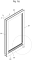
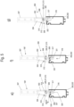
- Figure 1a shows a perspective view of a window 1 with a window frame 200 and a sash 100 arranged on it with one or more fittings (not shown here) so that it can be moved, in particular rotated and/or tilted.
- the sash 100 preferably has a sash frame 101 in which a surface element 102 set - in particular adhesively attached - is.
- the casement 101 has four angled, in Fig. 1a in each case at right angles to one another as a rectangular frame spars 103 to 106, to which the surface element 102 is fixed.
- the surface element 102 can, for example, be designed as a glass pane, in particular as an insulating glass pane. But it can also be designed as a metal plate or plastic plate.
- the configuration as an insulating glass pane is particularly preferred, with the frame being designed as the casement frame of a window or—in the context of the description of the figures, a synonymous term of a door—is designed.
- the invention is preferably embodied on a so-called door window.
- This is an element in which at least one casement 101, which is also closed around the periphery, is arranged on a peripherally closed frame 200 such that it can rotate and/or tilt in the manner of a window.
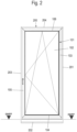
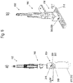
- a lower frame member 202 of the window frame 200 of the window 1 is designed in the manner of a ground sill and can also be used as a step sill or profile ( 2).
- 2 represents the usual installation position, which accommodates the window 1 on a building or in a building opening.
- the door is aligned vertically (XZ plane) and the vertically lower frame spar 202 of the frame 200 is also at the installation site on the building the lower vertical frame spar 104 of the wing frame 100.
- the frame members 103 to 106 of the casement frame 101 and the frame members of the window frame 200 are designed as so-called composite profiles and have at least one metal shell and at least one insulating bar zone (which is explained below by way of example) or have several metal profile zones and/or several insulating zones made of insulating bars or elements analogous to this.
- the sash frame 101 can initially have frame members 103 , 104 , 105 , 106 that are “identical” in cross-section all the way around, all of which are mitred and assembled to form the sash frame 101 that runs all the way around.
- the lower frame member 104 of the casement 101 then preferably has an attachment or an attachment profile 110 towards the bottom ( 2 ) which accommodates at least one functional element, for example a floor seal (not shown) and thus fills a gap between the outer edge of the actual composite profile of the lower casement frame spar 104 and the upper edge of the horizontally lower frame spar 202.
- the blind frame 200 also has a peripherally closed frame which is composed of preferably four frame bars 201, 202, 203, 204.
- the window frame 200 has an upper horizontal frame bar 204 and two vertical frame bars 201, 203.
- a lower horizontal frame rail 202 is also provided. He is here butt overlapping at right angles connected to the vertical frame members 201, 203 or attached to them.
- the respective horizontal upper frame bars 204, 106 and the vertical frame bars 201, 203 and 104, 106 can have the same cross section. Then they can be easily mitred and connected so well.
- the window 1 is designed as a door window and can be used or installed in a building opening in such a way that the lower frame member 202 of the window frame 200 is also used as a type of tread profile, so that its upper side can be designed flush with the surrounding floor area or When so mounted, the vertically lower frame members 202, 104 are preferably constructed differently and perform more functions than the remaining frame members.
- the abbreviation "OKFF” (upper edge of finished floor) in 2 denotes the top of the surrounding floor area of the window 1.
- the lower frame spar 202 of the frame 200 is below this level, so that the top of the lower horizontal frame spar 202 is at the OKFF level.
- the abbreviation “OKFF” also designates the top of the surrounding floor area of window 1 in the other figures.
- fittings are required to movably mount the sash or sash frame 101 on the frame 200. These fittings are arranged at various points between the window frame 200 and the sash frame 101 . They are not shown here.
- At least one turning function is implemented with the fittings in order to be able to open the leaf 100 by turning it about a vertical axis of rotation.
- a tilting function can also be realized with the fittings in order to be able to pivot the sash 100 into a tilted position about a lower horizontal axis of rotation provided in the lower area of the window 1 .
- the wing 100 extends in an X/Y plane.
- the Z-direction extends perpendicular to the image plane perpendicular to the main plane - the X/Y plane - of the window sash (see also 2 ).
- the frame bars 103 - 106 and 201 to 204 each have a main extension direction in which they run. In the case of light metal profiles, this is usually one way in which the light metal profiles are manufactured, which can be done, for example, by extrusion.
- the frame members 103 to 106 are assembled into a casement 101 with a rectangular shape. This is a particularly preferred embodiment, but not a mandatory embodiment.
- the window frame 200 also has a peripherally closed frame. This has a lower horizontal frame member 202, an upper horizontal frame member 204 and two vertical frame members 201, 203 which can have the same cross section and can be mitered together.
- the window 1 again has only one frame 200, but two wings 100, 100'.
- the first wing 100 is a so-called active wing and the second wing 100' is a so-called fixed wing.
- the active leaf 100 is the leaf that opens first and the fixed leaf 100' is the leaf that opens last of this two-leaf window 1, which can normally remain closed since ventilation or the like can take place via the active leaf 100.
- the fixed leaf 100' is consequently only opened in exceptional cases, for example when bulky objects are to be transported through a correspondingly large window opening.
- the passive leaf 100' is usually designed analogously to the active leaf 100.
- it can also have a plurality of wing frame struts 103', 104', 105', 106' which are connected to form a wing frame 101' and have a surface element 102' which is inserted into the wing frame 101'.
- the rabbet locking bolt 107' can be moved by a locking bar fitting 108' of the fixed leaf 100'.
- the rebate drive bolt 107' is guided in a bolt guide piece 109' of the fixed leaf 100'.
- the rabbet locking bar 107', the locking bar fitting 108' and the locking bar guide piece 109' can be arranged in a concealed manner in a vertical rebate space, so that these elements are not visible.
- the active leaf 100 can also have a lower rebate locking bolt 107 and preferably an upper rebate locking bolt (not shown here). have, with which the leaf 100 is set and locked on the frame 200.
- the rebate drive bolt 107 of the active leaf 100 can also be movable by a locking bar fitting 108 of the active leaf 100.
- the rebate drive bolt 107 of the active leaf 100 is guided in a bolt guide piece 109 of the active leaf 101 .
- the rebate locking bolt 107, the locking bar fitting 108 and the locking bar guide piece 109 can be arranged in a concealed manner in a vertical rebate space, so that these elements are not visible.
- the respective rabbet locking bar 107, 107' can be moved over the lower horizontal plane (XY plane according to Fig. 1b ) of the respective wing 100, 100' vertically, ie in the negative Z-direction Fig. 1b - Be moved out, so that it engages in a closed state of the respective leaf 100, 100' in a corresponding recess in the lower horizontal frame member 202 of the window frame 200.
- the term "closed state" of the wing 100, 100' is to be understood as meaning the state of the wing 100, 100' in which the rebate locking bolt 107, 107' of the wing 100, 100' is in the opening provided for this purpose in the Frame 200 or in a locking plate 318 that is attached to / in the frame 200 engages.
- the closed state of the inactive leaf 100' is easier to hit exactly during a closing process of the inactive leaf 100' and so that the inactive leaf 100' does not warp in this position over a longer period of time, it is provided that the inactive leaf 100' shortly before reaching the closed First a wing stop and support device 300 is activated and finally runs onto it in the closed state, with the wing stop and support device 300 being designed to stop the rotational movement of the fixed leaf 100' and to lift the fixed leaf 100' slightly so that the lower one from the Pivot facing away from the corner of the fixed leaf 100 'is firmly supported in the closed state.
- the sash stop and support device 300 can be formed on a single-sash window 1, but it can also be formed on a double-sash window 1.
- the sash stop and support device 300 is preferably formed on the fixed sash 100'.
- the wing stop and support device 300 is here - as in Figures 3b and 3c shown- on the bolt guide piece 109' of the rebate locking bolt 107' of the fixed leaf 100'.
- leaf stop and support device 300 which also serves to slightly raise the lower outer corner of the active leaf 100 in the closed state, so that this is also slightly relieved. This can be realized in different ways.
- a pin 301 is attached to the wing stop and support device 300, which moves in the horizontal direction—that is, in the X direction Fig. 1b - extends.
- the pin may have a roller 302 at its free end, as shown in 3c is shown. This is advantageous because it minimizes friction and wear, but is not essential.
- the pin 301 engages in a corresponding pocket which is formed on the latch guide piece 108 of the active leaf 100 .
- the traffic leaf 100 is advantageously reinforced in its closed state, so that subsequent locking by the locking bar fitting 108 and the espagnolette 107 can be carried out securely.
- the bag runs onto the roller 302, which lifts the leaf 100 slightly. This advantageously relieves the frame of the pedestrian leaf 100 against warping.
- a reverse arrangement is also conceivable, so that the roller 302 is attached to the active leaf 100 and the pocket is arranged on the fixed leaf 100'.
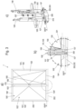
- the wing stop and support device 300 is in Figures 4a to 4c shown with the lower horizontal frame member 202 of the frame 200 without additional components.
- Figure 4a the wing stop and support device 300 is shown in a full section.
- the wing stop and support device 300 after Figures 4a to 4c has a housing 303, in whose interior 304 a support block and stop 305 with a rocker arm-like geometry here is mounted pivotably on an axis 306.
- the bearing block and stop 305 fulfills two functions: it serves as a stop for the fixed leaf 100', which becomes active when the fixed leaf 100' has reached its closed state, and as a bearing block, through which the fixed leaf 100' is raised slightly just before it has reached its closed state.
- the housing 303 is attached to a bar 307 .
- the housing 303 is fastened to the stationary leaf 100' via the strip 307.
- the housing 303 also has an opening 308 directed vertically downwards.
- the rocker arm-like geometry of the support block and stop 305 is divided into a support cam 309 and a counter-bearing cam 310 as well as a bearing section 311 with a bore through which the axis 306 passes.
- the support bracket and stop 305 are preferably made in one piece.
- the counter bearing cam 310 is supported on a counter bearing 312 in a support and stop position of the support block and stop 305, as shown in Figure 4a is shown.
- the bearing cam 309 is supported in a basic position of the bearing block and stop 305 on the counter bearing 312, as shown in Figure 5a is shown.
- the bearing cam 309 closes the opening 308 of the housing 303 together with the bearing section 311 so that the bearing block and stop 305 do not protrude beyond the outer contour of the housing 303 .
- the abutment 312 preferably has a cylindrical geometry and extends through the interior 304 of the housing 303 and is inserted at its two free ends in the housing 303 and fixed in the housing 303 in the axial direction, for example by a press fit.
- the support block and stop 305 is provided here with a recess 313 which encompasses the counter-bearing cam 310 and the bearing section 311 .
- the recess 313 serves to accommodate a restoring spring 314.
- the restoring spring 314 is preferably designed here as a space-saving torsion spring which is arranged around the axis 306 or is pushed onto the axis 306 and the recess 313 passes through.
- a first leg of the restoring spring 314 is supported on the recess 313 of the support bracket and stop 305 , while a second leg of the restoring spring 314 is supported in a bore 315 which is introduced into the housing 303 .
- the support block and stop 305 can preferably be moved by means of a magnetic principle of action.
- the pedestal and stop 305 can thus be moved by a permanent magnet or by an electromagnet, for example, and is preferably made of a ferromagnetic material.
- the return spring 314 is used to return the support bracket and stop 305 from the support and stop position -as in Figure 4a shown- in a basic position -as in Figure 5a shown- provided.
- the vane stopping and bearing device 300 may include an abutment 316 .
- This can preferably be designed to be adjustable in height, but is at a preset height during opening and closing of the fixed leaf 100' aligned.
- the abutment 316 is designed according to FIG Figures 4a - c and Figures 5a-g used in the lower horizontal frame member 202 of the frame 200.
- the support cam 309 of the support block and stop 305 engages in the abutment 316 in its support and stop position.
- a pivoting drive means 317 is required for pivoting the support bracket and stop 305 in order to bring the support bracket and stop 305 from its basic position into the support and stop position shortly before the inactive leaf 100' reaches the closed state.
- the swivel drive means 317 is formed here by a permanent magnet, in particular by a neodymium magnet.
- the pivoting drive means 317 pivots the support bracket and stop 305 into the closed state from the basic position of the support bracket and stop 305, in which the support cam 309 is aligned horizontally, to the support and stop position of the support bracket and stop 305. in which the bearing cam 309 is aligned vertically and the bearing cam 309 engages in the abutment 316.
- the fixed leaf 100' Due to the kinetic energy of the fixed leaf 100', the fixed leaf 100' is raised somewhat when the support bracket and stop 305 is moved into the vertical position of the support cam 309 or into the support and stop position of the support bracket and stop 305, which causes the freely projecting part of the fixed leaf 100' -so after Figure 3a the lower right corner of the fixed leaf 100'- of the window 1 is relieved and thus warping of the fixed leaf 100' is prevented.
- the abutment 316, the pivoting drive means 317 and the recesses into which the rabbet locking bolts 107, 107' engage can be combined in the locking plate 318, which is inserted in the lower horizontal frame member 202 of the window frame 200, as is shown in 3c , Figures 4a - c as well as Figures 5a-g is shown.
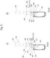
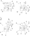
- Figures 5a-g shows the approach process of the inactive leaf 100' in its closed state and the reaching of the closed state as well as the associated pivoting process of the support bracket and stop 305, in which the support cam 309 is brought from its horizontal basic position into its vertical support and stop position.
- the swivel drive means 317 is designed in such a way that it swivels the support block and stop 305 out of its basic position against the resistance of the return spring 314 .
- FIG 5a the inactive leaf 100' is shown in an approaching process in its closed state.
- the support block and stop 305 is in its basic position, in which the support cam 309 of the support block and stop 305 is aligned horizontally and the opening 308 of the housing 303 is thereby closed.
- the abutment cam 310 of the support block and stop 305 is supported on one side of the interior 304 of the housing 303 .
- the support block and stop 305 are held in this position by the force of the return spring 314 .
- Figure 5b is shown how the fixed leaf 100' further approaches its closed state.
- the bearing block and stop 305 sweep over the pivoting drive means 317, the bearing block and stop 305 leave their basic position as a result of the magnetic field acting on them - the force of which overcomes the opposing force of the return spring 314 - and is brought into a pivoting movement, so that the bearing cam 309 moves in its place leaves the horizontal position.
- FIG. 5c is shown how the fixed leaf 100' further approaches its closed state. Due to the magnetic field acting on it, the bearing cam 309 of the bearing block and stop 305 has slid along with a rounded edge 319 on the pivoting drive means 317 in order then, while continuing its pivoting movement, to engage in a recess 320 formed by the abutment 316, which is formed by a bearing surface 321 of the abutment 316 and a first wall 322 and a second wall 323 is limited.
- the abutment 316 is preferably designed as a type of threaded pin or bolt and is inserted into a corresponding bore that has a female thread at least over a partial length.
- the bore can be longer than the abutment 316, so that the depression 320 is formed in that the abutment 316 does not fill the bore over its entire length.
- the first wall 322 and the second wall 323 are thus formed by the bore.
- the wing stop and support device 300 thus works more or less according to the positive locking principle.
- form closure means that one connection partner is in the way of the other.
- the two connection partners - here the support cam 309 of the support block and stop 305 and the recess 320 - produce the positive connection through the interlocking.
- the connection partners cannot become detached even without power transmission or when power transmission is interrupted.
- the form fit is also achieved solely by an opening movement of the Fixed leaf 100' automatically abandoned again, ie it does not require manual unlocking, for example by a user of the door.
- the first wall 322 of the depression 320 is closer to the swivel drive means 317 than the second wall 323.
- the continuing swivel movement of the support block and stop 305 is caused by the magnetic field of the swivel drive means still acting on the support block and stop 305, in particular on its support cam 309 317 enabled.
- Figure 5d is shown how the fixed leaf 100' further approaches its closed state.
- the bearing cam 309 of the bearing block and stop 305 continues its pivoting movement via the rounded edge 319 in contact with the bearing surface 321 of the depression 320 which forms the abutment 316 .
- FIG. 5e is shown how the fixed leaf 100' further approaches its closed state.
- the bearing cam 309 of the support block and stop 305 continues its pivoting movement, rolling over the rounded edge 319, now over a surface 324 at its free end areal contact with the bearing surface 321 of the recess 320 of the abutment 316, so that the bearing cam 309 is now vertical is aligned and the counter-bearing cam 310 of the support block and stop 305 is supported on the counter-bearing 312.
- the freely overhanging part of the inactive leaf 100' is raised slightly and thereby advantageously protected against warping.
- the abutment 316 is equipped with a height adjustment device, via which the support surface 321 can be adjusted in height.
- the abutment 316 is preferably adjustable in height by means of a thread. As a result, the amount by which the freely projecting part of the fixed leaf 100' is raised can be set easily, quickly and with great accuracy.
- Fig 5f is shown how the fixed leaf 100 'has almost reached its closed state. Due to its kinetic energy, the inactive leaf 100' slides with a freely projecting end that is slightly raised in the vertical direction over the surface 324 at the free end of the bearing cam 309 on the bearing surface 321 of the abutment 316.
- Fig. 5g is shown that the fixed leaf 100 'has reached its closed state.
- the bearing cam 309 of the bearing block and stop 305 has the second wall while continuing its sliding movement, in which it slides with its surface 324 at its free end over the bearing surface 321 of the abutment 316 323 contacted, which serves as a stop for the support cam 309 of the support block and stop 305 and thus also for the fixed leaf 100'.
- FIG. 6a, b and 7a - d An embodiment of the invention is in the Figures 6a, b and 7a - d shown.
- the abutment 316 is formed in the fixed leaf 101 ′ and the movable bearing cam 309 is arranged on or in the lower horizontal frame member 202 of the window frame 200 .
- the support bracket and stop 305 can be accommodated in a separate striker plate 318, as shown in Fig. 6a, b is shown.
- the support block and stop 305 can also be accommodated directly in the lower horizontal frame member 202 of the window frame 200, ie without the locking plate 318.
- the function of the support block and stop 305 is analogous to that in FIGS Figures 4a - c and 5a - g , like this in Figure 7a - d is shown.
- FIG 7a the support block and stop 305 is shown in its basic position.
- the support cam 309 is in the basic position of the support bracket and stop 305 in a first recess 325 provided for this purpose in the striker plate 318 or in the lower horizontal frame member 202 of the window frame 200.
- the support block and stop 305 also shows in the design variant Figures 6a and 6b as well as Fig. 7a - d the cylindrical bearing portion 311 on.
- the abutment section 310 is not required here and is therefore not formed here.
- the return spring 314 can also be omitted here because the bearing cam 309 of the support bracket and stop 305 returns to its basic position due to the force of gravity acting on it when the fixed leaf 100' is opened and the bearing cam is no longer in the effective range of the swivel drive means 317.
- the pivoting drive means 317 which is also preferably designed as a permanent magnet here, moves the support bracket and stop 305 with forced into a pivoting movement from its basic position by its support cam 309, as is shown in Figure 7b -analogous to Figure 5b - is shown.
- FIG. 7d is shown how the fixed leaf 100' further approaches its closed state.
- the bearing cam 309 of the support block and stop 305 continues its pivoting movement, rolling over the rounded edge 319, now over a surface 324 at its free end areal contact with the bearing surface 321 of the recess 320 of the abutment 316, so that the bearing cam 309 is now vertical is aligned.
- the freely overhanging part of the inactive leaf 100' is raised slightly and thereby advantageously protected against warping.
- the abutment 316 is equipped with a height adjustment device, via which the support surface 321 can be adjusted in height.
- the abutment 316 is preferably adjustable in height by means of a thread. As a result, the amount by which the freely projecting part of the fixed leaf 100' is raised can be set easily, quickly and with great accuracy.
- the sash stop and support device 300 is embodied here on a two-sash window 1 . However, it can also be formed on a single-leaf window 1 . In a double-leaf window 1, it is preferably formed on the fixed leaf 100' or acts on the fixed leaf 100'. However, it can also be formed on the active leaf 100 or act on the active leaf 100 .
- the wing stop and support device 300 thus has a number of advantages. Due to its simple structure, which is limited to just a few components, it enables reliable function over the long term and is very compact. Furthermore, it creates a stable and safe support as well as a safe and precise stop and does not require expensive electrical actuators and drives. Further will the sash stop and support device 300 does not impede or give up the accessibility of the window 1 when the sash 100, 100' is open.
- wing 100, 100' sash frame 101, 101' surface element 102, 102' frame rails 103, 103', 104, 104', 105, 105', 106, 106' Seam locking bar 107, 107' latch bar fitting 108, 108' bolt guide piece 109, 109' heel profile 110 frame 200 frame rails 201, 202, 203, 204 Wing stop and support device 300 cones 301 role 302 Housing 303 inner space 304 support bracket and stop 305 axis 306 strip 307 opening 308 bearing cam 309 counter bearing cam 310 storage section 311 counter bearing 312 recess 313 return spring 314 drilling 315 abutment 316 pan drive means 317 locking plate 318 Rounded edge 319 deepening 320 bearing surface 321 first wall 322 second wall 323 Surface 324 First deepening 325 Second deepening 326
Landscapes
- Engineering & Computer Science (AREA)
- Civil Engineering (AREA)
- Structural Engineering (AREA)
- Mechanical Engineering (AREA)
- Wing Frames And Configurations (AREA)
Abstract
Description
- Die vorliegende Erfindung betrifft ein Fenster nach dem Oberbegriff des Anspruchs 1.
- In dieser Schrift werden die Begriffe "Tür" und "Fenster" synonym verwendet. Dort, wo Elemente eines Fensters beschrieben werden, können die Beschreibungen dieser Elemente zum Stand der Technik und zur Erfindung auch auf eine Tür bezogen werden, da diese sich nur durch die Bauart des Blendrahmens von einer Tür unterscheidet, was sich hier in den Ansprüchen nicht niederschlägt.
- Die Erfindung betrifft insofern insbesondere ein sogenanntes Türfenster. Dies ist ein Fenster mit einem umlaufenden Blendrahmen und einem am Blendrahmen beweglich geführten Flügel, wobei der untere horizontale Blendrahmenholm im eingebauten Zustand vorzugsweise ganz oder nahezu mit dem umgebenden Boden fluchtet und ggf. auch als Trittprofil genutzt wird.
- Ein gattungsgemäßes Türfenster ist aus der
DE 10 2018 112 430 A1 bekannt. Diese Schrift offenbart sein solches Fenster und beschäftigt sich mit der Frage einer guten Abdichtung des Spalts zwischen dem unteren Flügelrahmenholm und dem unteren Blendrahmenholm im geschlossenen Zustand. - Bei gattungsgemäßen sowie auch bei erfindungsgemäßen Fernstern dieser Artalso insbesondere bei bodentiefen, barrierefreien, sogenannten Null-Niveau Fenstern -die auch als Schwenkflügeltür verwendbar sind - kann zumindest der untere Blendrahmenholm im Boden versenkt und damit nicht sichtbar sein, so dass ein solches Fenster eine blendrahmenfreie Optik mit einer entsprechend großen sichtbaren Verglasungsfläche ermöglicht. Ferner ermöglicht diese Bauweise des Fensters vorteilhaft eine barrierefreie Bodenschwelle.
- Durch die barrierefreie Bodenschwelle ergibt sich das Problem, dass durch herkömmliche Anschläge, die erforderlich sind, um beispielsweise für einen Schwenkflügel in Bezug auf seinen Schwenkwinkel einen geschlossenen Zustand zu definieren oder eine vertikale Höhenlage des freien auskragenden Teils des Schwenkflügels in dem geschlossenen Zustand zu definieren, die Barrierefreiheit der Bodenschwelle aufgegeben wird, was unerwünscht ist.
- Weiterhin sind aus dem Stand der Technik Türstopper bekannt, mit denen Türflügel in einer geöffneten Position gehalten werden können. Bei der in der
DE 71 080 80 beschriebenen Feststelleinrichtung für eine geöffnete Tür ist es vorgesehen, dass am unteren Ende eines auf- und abwärtsbewegbar gelagerten, durch eine vorgespannte Schraubenfeder in der oberen Endlage gehaltenen und gegenüber einem Gehäuse verklemmbaren Schaftes ein keilartig wirkendes Sperrglied angeordnet ist, das beim Schwenken der geöffneten Tür in Schließrichtung selbsttätig in eine Klemmlage bewegt wird und somit die Tür gegenüber dem Fußboden feststellt. - Nachteilig ist hierbei, dass der Türstopper manuell, d.h. durch einen Benutzer der Tür aus seiner Feststellposition gelöst werden muss.
- Ausgehend vom Stand der Technik ist die Aufgabe der Erfindung, ein Fenster, insbesondere ein Türfenster bereitzustellen, bei welchem diese Probleme im Wesentlichen gelöst sind.
- Die vorliegende Erfindung löst die Aufgabe durch ein Fenster mit den Merkmalen des Anspruches 1.
- Demnach wird ein Fenster, insbesondere Türfenster geschaffen, mit einem Blendrahmen und wenigstens einem daran drehbar befestigten Flügel, der wenigstens einen Flügelrahmen aufweist, wobei der Flügelrahmen ein Flächenelement aufnimmt und der Flügelrahmen aus mehreren Flügelrahmenholmen zusammengesetzt ist und mit Beschlägen zum drehbeweglichen Bewegen des Flügels relativ zum Blendrahmen in einen geöffneten Zustand und in einen geschlossenen Zustand, wobei vorzugsweise zum Verriegeln des Flügels in dem geschlossenen Zustand ein beweglicher Falztreibriegel vorgesehen ist, der in den Blendrahmen - insbesondere in ein Schließblech, dass am / im Blendrahmen befestigt ist - beweglich ist und dann dort eingreift, sowie wenigstens eine Flügelstopp- und Auflagereinrichtung, die dazu ausgelegt ist, eine Drehbewegung des Flügels zu stoppen, wobei die Flügelstopp- und Auflagereinrichtung ferner dazu ausgelegt ist, den Flügel anzuheben, so dass eine untere, vom Drehbeschlag abgewandte Ecke des Flügels in dem geschlossenen Zustand fest abgestützt ist und die Flügelstopp- und Auflagereinrichtung einen durch ein magnetisches Schwenkantriebsmittel beweglichen Auflagerblock und Anschlag mit einem Auflagernocken am Flügel oder Blendrahmen aufweist sowie ein Widerlager am Blendrahmen oder Flügel aufweist, in das der Auflagernocken zumindest in dem geschlossenen Zustand des Flügels eingreift.
- Im Rahmen dieser Schrift ist unter dem Begriff "geschlossener Zustand" des Flügels der Zustand des Flügels zu verstehen, in dem der Falztreibriegel des Flügels in der dafür vorgesehenen Öffnung in den Blendrahmen oder in das Schließblech, dass am / im Blendrahmen befestigt ist, eingreifen kann oder eingreift.
- Die derart ausgestaltete Flügelstopp- und Auflagereinrichtung weist eine Reihe von Vorteilen auf. Sie ermöglicht -wegen ihrem einfachen, auf wenige Bauteile beschränkten Aufbau- dauerhaft eine sichere Funktion und baut dabei sehr kompakt. Ferner schafft sie unter Beibehaltung der Barrierefreiheit des Fensters bei geöffnetem Flügel eine stabile und sichere Abstützung sowie einen sicheren und präzisen Anschlag und kommt ohne kostenintensive elektrische Aktuatoren und Antriebe aus. Der Falztreibriegel kann - wenn vorgesehen - durch den präzisen Stopp beim Schliessen sehr gut betätigt werden
- In einer besonders bevorzugten Ausführungsvariante der Erfindung ist vorgesehen, dass der Flügel kippbar an dem Blendrahmen befestigt ist, sowie Beschläge zum kippbeweglichen Bewegen des Flügels relativ zum Blendrahmen aufweist. Dadurch kann das Fenster z.B. zum Lüften in eine Kippstellung gebracht werden und muss nur zum Hindurchgehen durch eine Drehbewegung geöffnet werden.
- In einer weiteren besonders bevorzugten Ausführungsvariante der Erfindung ist vorgesehen, das Fenster zwei Flügel aufweist, wobei einer der Flügel als Gehflügel und einer als Standflügel ausgebildet ist, wobei zumindest einer der Flügel - insbesondere der Standflügel - die Flügelstopp- und Auflagereinrichtung aufweisen kann und der andere Flügel - insbesondere der Gehflügel - optional eine Flügelstopp- und Auflagereinrichtung aufweisen kann oder keine solche aufweisen kann. Dadurch müssen nicht stets beide Flügel zum Lüften oder zum Hindurchgehen geöffnet werden. Bei einer solchen Anordnung ist die Erfindung besonders vorteilhaft einsetzbar.
- In einer weiteren besonders bevorzugten Ausführungsvariante der Erfindung ist weiterhin vorgesehen, dass beide Flügel jeweils einen Falztreibriegel aufweisen. Dadurch kann der jeweilige Flügel einfach und sicher ist seinem geschlossenen Zustand verriegelt werden.
- In einer weiteren besonders bevorzugten Ausführungsvariante der Erfindung ist ferner vorgesehen, dass das Widerlager höhenverstellbar ausgelegt ist, insbesondere, dass das Widerlager durch ein Gewinde höhenverstellbar ist und als eine Art Gewindestift oder -bolzen ausgebildet ist und in eine korrespondierende Bohrung eingesetzt ist, die zumindest auf einer Teillänge ein Mutterngewinde aufweist. Dadurch kann das Widerlager konstruktiv einfach, schnell und präzise auf den jeweiligen Flügel angepasst werden.
- In diesem Zusammenhang ist kann in einer weiteren bevorzugten Ausführungsvariante der Erfindung vorgesehen sein, dass das Widerlager während eines Öffnens und Schließens des Flügels in einer voreingestellten Höhe ausrichtbar ist bzw. dann ausgerichtet ist. Dadurch ergibt sich vorteilhaft stets ein geschlossener Zustand des Flügels, bei dem der Flügel entlastet ist.
- Ferner kann in einer weiteren besonders bevorzugten Ausführungsoption der Erfindung vorgesehen sein, dass die Flügelstopp- und Auflagereinrichtung an einem Riegelführungsstück des Falztreibriegels des jeweiligen Flügels angeordnet ist. Dadurch wird eine bauraumsparende Anordnung der Flügelstopp- und Auflagereinrichtung geschaffen.
- Weiterhin kann in einer weiteren besonders bevorzugten Ausführungsoption der Erfindung vorgesehen sein, die Flügelstopp- und Auflagereinrichtung nach einem Formschlussprinzip arbeitet, wobei der Formschluss allein durch eine Öffnungsbewegung des Flügels selbsttätig wieder aufgegeben wird. Dadurch wird eine besonders einfache Funktion der Flügelstopp- und Auflagereinrichtung ermöglicht, die für einen Benutzer keinerlei Bedienungsaufwand erfordert. Ferner wird eine dauerhaft zuverlässig arbeitende Flügelstopp- und Auflagereinrichtung mit einer robusten und sicheren Anschlagfunktion geschaffen.
- Es kann ebenfalls in einer weiteren besonders bevorzugten Ausführungsvariante der Erfindung vorgesehen sein, dass an der Flügelstopp- und Auflagereinrichtung eine Zusatzauflage eingerichtet ist, welche dazu dient, im geschlossenen Zustand auch die untere äußere Ecke des Flügels ohne Flügelstopp- und Auflageeinrichtung leicht anzuheben, damit auch dieser entlastet wird. Dadurch wird eine Möglichkeit geschaffen, mit der der Flügel ohne Flügelstopp- und Auflageeinrichtung in seinem geschlossenen Zustand leicht angehoben und damit entlastet wird.
- Weiterhin kann in einer weiteren besonders bevorzugten Ausführungsvariante der Erfindung vorgesehen sein, dass an der Flügelstopp- und Auflageeinrichtung ein Zapfen befestigt ist, der sich in horizontaler Richtung erstreckt und dessen freies Ende eine Rolle aufweist. Weiterhin kann in diesem Zusammenhang vorgesehen sein, dass beim Schliessen des Flügels ohne Flügelstopp- und Auflageeinrichtung eine Tasche, die der Flügel ohne Flügelstopp- und Auflagereinrichtung aufweist, auf die Rolle aufläuft. Dadurch wird konstruktiv einfach eine Möglichkeit geschaffen, mit der der Flügel ohne Flügelstopp- und Auflageeinrichtung in seinem geschlossenen Zustand leicht angehoben und damit entlastet wird.
- Es kann ebenfalls in einer weiteren besonders bevorzugten Ausführungsvariante der Erfindung vorgesehen sein, dass die Flügelstopp- und Auflagereinrichtung ein Gehäuse aufweist, das an einer Leiste befestigt ist und in dem Innenraum des Gehäuses ein Auflagerbock und Anschlag schwenkbar auf einer Achse gelagert ist und das Gehäuse eine vertikal nach unten gerichtete Öffnung aufweist. Dadurch wird konstruktiv einfach ein Bauraum für das bewegliche Bauteil der Flügelstopp- und Auflagereinrichtung geschaffen.
- Es kann ferner in einer weiteren besonders bevorzugten Ausführungsvariante der Erfindung vorgesehen sein, dass der Auflagebock und Anschlag einstückig ausgeführt ist und durch ein magnetisches Wirkprinzip bewegbar ist. Durch die Einstückigkeit des Auflagerbocks und Anschlags ergibt sich eine kompakt bauende und aus wenigen Bauteilen aufgebaute Flügelstopp- und Auflagereinrichtung. Ferner ergibt sich durch das magnetische Wirkprinzip eine konstruktiv einfache Bewegbarkeit für den Auflagerbock und Anschlag.
- Ferner kann in einer weiteren besonders bevorzugten Ausführungsoption der Erfindung vorgesehen sein, dass sich die Geometrie des Auflagerbocks und Anschlags mindestens in den Auflagernocken sowie in einen Lagerabschnitt gliedert. Durch die Funktionsintegration der beiden Funktionen in ein Bauteil ergibt sich eine kompakt bauende und aus wenigen Bauteilen aufgebaute Flügelstopp- und Auflagereinrichtung.
- Alternativ kann in einer weiteren bevorzugten Ausführungsoption der Erfindung vorgesehen sein, dass der Lagerabschnitt in eine weitere, zweite Vertiefung eingreift, wobei eine metallische Überdeckung in vertikaler Richtung gebildet ist, so dass ein Lager gebildet ist. Dadurch entsteht ein besonders einfach aufgebautes Lager des Auflagerbocks und Anschlags, in dem der Umfang des Lagerabschnitts des Auflagerbocks und Anschlags die eine Kontaktfläche des Lagers ist, so dass auf eine separate Achse verzichtet werden kann.
- Ebenfalls kann nach einer weiteren besonders bevorzugten ausführungsvariante der Erfindung vorgesehen sein, dass der Auflagerbock und Anschlag einen Gegenlagernocken aufweist. In diesem Zusammenhang kann vorgesehen sein, dass sich der Gegenlagernocken in einer Auflager- und Anschlagposition des Auflagerbocks und Anschlags an einem Gegenlager abstützt. Dadurch wird konstruktiv einfach ein robustes Auflager und ein ebenso robuster Anschlag für den jeweiligen Flügel geschaffen.
- Vorgesehen kann in einer weiteren besonders bevorzugten Ausführungsvariante auch sein, dass der Anschlagnocken sich in einer Grundposition des Auflagerbocks und Anschlags an dem Gegenlager abstützt und dabei der Anschlagnocken gemeinsam mit dem Lagerabschnitt die Öffnung des Gehäuses verschließt, so dass der Auflagerbock und Anschlag nicht über eine Außenkontur des Gehäuses hervorsteht. Dadurch ist der Auflagerbock und Anschlag wirkungsvoll gegen Beschädigung geschützt.
- Alternativ dazu kann nach einer weiteren besonders bevorzugten Ausführungsoption der Erfindung vorgesehen sein, dass der Auflagernocken in der Grundposition des Auflagerbocks und Anschlags in einer dafür vorgesehenen ersten Vertiefung im Schließblech oder im unteren horizontalen Rahmenholm des Blendrahmens liegt. Auch dadurch ist der Auflagerbock und Anschlag gegen Beschädigung geschützt. Ferner wird dadurch die Barrierefreiheit des Fensters konstruktiv einfach gewährleistet.
- Weiterhin kann in einer weiteren besonders bevorzugten Ausführungsvariante der Erfindung vorgesehen sein, dass der Auflagernocken des Auflagerbocks und Anschlag eine abgerundete Kante aufweist. Durch die abgerundete Kante wird konstruktiv einfach das verkantungsfreie und damit sichere Eingreifen des Auflagernockens in das dafür vorgesehene Widerlager gewährleitstet.
- Ebenfalls kann nach einer weiteren besonders bevorzugten Ausführungsform der Erfindung vorgesehen sein, dass der Auflagerbock und Anschlag mit einer Ausnehmung versehen ist, die den Gegenlagernocken sowie den Lagerabschnitt umfasst und zur Aufnahme einer Rückstellfeder dient. Dadurch wird konstruktiv einfach ein kompakter Bauraum für eine Rückstellfeder geschaffen.
- Ferner kann in einer weiteren besonders bevorzugten Ausführungsvariante der Erfindung vorgesehen sein, dass das Schwenkantriebsmittel durch einen Permanentmagneten, insbesondere durch einen Neodym-Magneten gebildet ist. Dadurch ergibt sich ein konstruktiv einfach realisierbares und dauerhaft sicher arbeitendes Schwenkbetriebsmittel.
- Weiterhin kann in einer weiteren besonders bevorzugten Ausführungsvariante der Erfindung vorgesehen sein, dass das Schwenkantriebsmittel derart ausgelegt ist, dass es den Auflagerbock und Anschlag gegen den Widerstand der Rückstellfeder aus seiner Grundposition herausschwenkt. Dadurch ergibt sich eine konstruktiv einfache und dauerhaft sichere Aktuatorik für den Auflagerbock und Anschlag.
- In einer weiteren besonders bevorzugten Ausführungsvariante der Erfindung ist ferner vorgesehen, dass das Widerlager, das Schwenkantriebsmittel sowie Ausnehmungen, in die die Falztreibriegel eingreifen, in einem Schließblech zusammengefasst sind, welches in dem unteren horizontalen Rahmenholm des Blendrahmens eingesetzt ist. Dadurch wird ein einfach zu montierendes, funktionsintegrierendes Bauteil geschaffen.
- Alternativ dazu kann nach einer weiteren besonders bevorzugten Ausführungsoption der Erfindung vorgesehen sein, dass das Widerlager mit der Vertiefung sowie das Schwenkantriebsmittel im Riegelführungsstück des Falztreibriegels des Flügels integriert sind. Diese Anordnung verbessert vorteilhaft die kompakte Bauweise der Flügelstopp- und Auflageeinrichtung.
- Weiterhin kann in einer weiteren besonders bevorzugten Ausführungsvariante der Erfindung vorgesehen sein, dass der Auflagernocken des Auflagerbocks und Anschlag eine Fläche an seinem freien Ende aufweist. Dadurch wird die auf die Kontaktfläche wirkende Flächenpressung verringert oder vermieden und damit ein möglicher Verschleiß des Auflagernockens und / oder des Widerlagers verringert oder ganz vermieden. Ferner wird derart ein auch unter Last stabil in seiner definierten Lage verbleibender Auflagernocken geschaffen.
- Vorgesehen kann in einer weiteren besonders bevorzugten Ausführungsvariante auch sein, dass der Auflagernocken des Auflagerbocks und Anschlag in dem geschlossenen Zustand des Flügels eine zweite Wandung einer Vertiefung im Widerlager kontaktiert, die als Anschlag für den Auflagernocken des Auflagerbocks und Anschlag und damit auch für den Standflügel dient. Dadurch wird eine definierter Anschlagposition für den Auflagernocken und damit für den Flügel geschaffen.
- Weitere vorteilhafte Ausgestaltungen sind den Unteransprüchen zu entnehmen.
- Nachfolgend wird die Erfindung unter Bezug auf die Figuren näher beschrieben. Diese Figuren zeigen bevorzugte Ausführungsbeispiele der Erfindung. Anzumerken ist, dass die Erfindung nicht auf diese Ausführungsbeispiele beschränkt werden kann, sodann dass auch andere, hier nicht gezeigte Ausführungsvarianten im Rahmen der Ansprüche realisierbar sind sowie Äquivalente und Abwandlungen der dargestellten Figuren, die Rahmen der Schutzbereiche liegen. Es zeigen:
- Figur 1:
- in a) eine perspektivische Ansicht eines Fensters, das für einen Einsatz in Kombination mit einer erfindungsgemäßen Flügelstoppvorrichtung geeignet ist, mit Blendrahmen und Flügel und in b) den Blendrahmen-ohne Flügel - des Fensters aus a) in einer relativ zu a) gedrehten perspektivischen Ansicht;
- Figur 2:
- eine Vorderansicht des Fensters aus
Fig. 1 ), die das Fenster im eingebauten Zustand zeigt; - Figur 3:
- in a) eine schematisierte Vorderansicht eines weiteren Fensters, das für einen Einsatz in Kombination mit einer erfindungsgemäßen Flügelstoppvorrichtung geeignet ist, in b) eine detailliertere und teilweise mit ausgeblendeter Profilflächen Ausschnittsvergrößerung des Bereiches "A" aus a) und in c) eine perspektivische Ansicht von Beschlagelementen des Fensters aus a) mit einer ersten Flügelstoppvorrichtung;
- Figur 4:
- in a) bis c) eine Schnittansicht und zwei verschiedene perspektivische Ansichten der Flügelstoppvorrichtung aus
Fig. 3c ); - Figur 5:
- in a) bis g) Schnittansichten durch den Bereich eines Schwellenprofils des Blendrahmens und durch die Stoppvorrichtung des Flügels der
Fig. 4a ) bis c), zur Veranschaulichung des Verhaltens der Stoppvorrichtung bei einem Schliessen des Flügels, wobei dieFig. 5 ) a) bis g) aufeinanderfolgende Stellungen bei einem Schliessen des Flügels veranschaulichen; und - Figur 6:
- in a) bis b) eine Schnittansicht und eine perspektivische Ansicht einer zweiten Flügelstoppvorrichtung;
- Figur 7:
- in a) bis d) Schnittansichten durch den Bereich eines Schwellenprofils des Blendrahmens und durch eine zweite Flügelstoppvorrichtung, insbesondere für einen Flügel nach Art der
Fig. 2 , wobei dieFig. 7 ) a) bis d) aufeinanderfolgende Positionen bei einem Schließen des Flügels veranschaulichen. -
Figur 1a zeigt eine perspektivische Ansicht eines Fensters 1 mit einem Blendrahmen 200 und einem daran mit einem oder mehreren Beschlägen (hier nicht dargestellt) beweglich, insbesondere drehbar und/oder kippbar angeordneten Flügel 100. Der Flügel 100 weist vorzugsweise einen Flügelrahmen 101 auf, in dem ein Flächenelement 102 festgelegt - insbesondere klebend befestigt - ist. - Der Flügelrahmen 101 weist vier winklig, in
Fig. 1a jeweils rechtwinklig, zueinander als in Rechteckform ausgerichtete Rahmenholme 103 bis 106 auf, an denen das Flächenelement 102 festgelegt ist. Das Flächenelement 102 kann beispielsweise als Glasscheibe, insbesondere als Isolierglasscheibe ausgebildet sein. Es kann aber auch als Metallplatte oder Kunststoffplatte ausgebildet sein. Besonders bevorzugt ist im Rahmen der Umsetzung der vorliegenden Erfindung die Ausgestaltung als Isolierglasscheibe, wobei der Rahmen als Flügelrahmen eines Fensters oder- im Rahmen der Figurenbeschreibung ein synonymer Begriff einer Tür - ausgelegt ist. - Die Erfindung wird dabei bevorzugt an einem sogenannten Türfenster ausgebildet. Dies ist ein Element, bei dem an einem umfangsgeschlossenen Blendrahmen 200 wenigstens ein ebenfalls umfangsgeschlossener Flügelrahmen 101 dreh- und/oder kippbeweglich nach Art eines Fensters angeordnet ist. Dabei ist - daher der Begriff "Türfenster" ein unterer Rahmenholm 202 des Blendrahmens 200 des Fensters 1 nach Art einer Bodenschwelle ausgebildet und kann auch als Trittschwelle bzw. -profil genutzt werden (
Fig. 2). Fig. 2 gibt die übliche Einbaustellung wieder, die das Fenster 1 an einem Gebäude bzw. in einer Gebäudeöffnung aufnimmt. Dabei ist die Tür vertikal ausgerichtet (X-Z-Ebene) und der vertikal untere Rahmenholm 202 des Blendrahmens 200 ist auch am Einbauort am Gebäude der vertikal untere Rahmenholm 202 des Blendrahmens 200 und der vertikale untere Rahmenholm 104 des Flügelrahmens 101 ist entsprechend auch am Einbauort am Gebäude der untere vertikale Rahmenholm 104 des Flügelrahmens 100. - Vorzugsweise sind die Rahmenholme 103 bis 106 des Flügelrahmens 101 und die Rahmenholme des Blendrahmens 200 als sogenannte Verbundprofile ausgebildet und weisen wenigstens eine Metallschale und wenigstens eine Isolierstegzone auf (was weiter unten beispielhaft erläutert wird) oder weisen mehrere Metallprofilzonen und/oder mehrere Isolierzonen aus Isolierstegen oder dazu analogen Elementen auf.
- Der Flügelrahmen 101 kann zunächst umlaufend vom Querschnitt her "gleiche" Rahmenholme 103, 104, 105, 106 aufweisen, die allesamt auf Gehrung geschnitten und zu dem umlaufenden Flügelahmen 101 zusammengesetzt sind. Vorzugsweise weist dann der untere Rahmenholm 104 des Flügelrahmens 101 nach unten hin aber ergänzend einen Ansatz oder ein Ansatzprofil 110 auf (
Fig. 2 ), welches zumindest ein Funktionselement, beispielsweise eine Bodendichtung (nicht dargestellt) aufnimmt und derart einen Spalt zwischen dem äußeren Rand des eigentlichen Verbundprofils des unteren Flügelrahmenholms 104 und dem oberen Rand des horizontal unteren Blendrahmenholms 202 ausfüllt. - Der Blendrahmen 200 ebenfalls einen umfangsgeschlossenen Rahmen auf, der aus vorzugsweise vier Rahmenholmen 201, 202, 203, 204 zusammengesetzt ist. Der Blendrahmen 200 verfügt über einen oberen horizontalen Rahmenholm 204 und zwei vertikale Rahmenholme 201, 203 auf. Es ist zudem ein unterer horizontaler Rahmenholm 202 vorgesehen. Er ist hier stumpf rechtwinklig überlappend mit den vertikalen Rahmenholmen 201, 203 verbunden bzw. an diese angesetzt. Die jeweils horizontal oberen Rahmenholme 204, 106 sowie die vertikalen Rahmenholme können 201, 203 sowie 104, 106 einen gleichen Querschnitt aufweisen. Dann sind sie gut auf Gehrung schneidbar und derart gut zu verbinden.
- Da das Fenster 1 als ein Türfenster ausgebildet ist und nutzbar ist bzw. in eine Gebäudeöffnung so einbaubar ist, dass der untere Rahmenholm 202 des Blendrahmens 200 auch als eine Art Trittprofil genutzt wird, so dass seine Oberseite mit dem umgebenden Bodenbereich fluchtend ausgebildet sein kann bzw. so montiert sein kann, sind die vertikal unteren Rahmenholme 202, 104 vorzugsweise anders aufgebaut und realisieren mehr Funktionen als die übrigen Rahmenholme.
- Die Abkürzung "OKFF" (Oberkante Fertigfußboden) in
Fig. 2 kennzeichnet die Oberseite des umgebenden Bodenbereichs des Fensters 1. Der untere Rahmenholm 202 des Blendrahmens 200 liegt unter diesem Niveau, so dass die Oberseite des unteren horizontalen Rahmenholms 202 auf dem OKFF-Niveau liegt. Die Abkürzung "OKFF" kennzeichnet auch in den anderen Figuren die Oberseite des umgebenden Bodenbereichs des Fensters 1. - Zum beweglichen Lagern des Flügels oder Flügelrahmens 101 an dem Blendrahmen 200 sind mehrere Beschläge erforderlich. Diese Beschläge sind an verschiedenen Stellen zwischen dem Blendrahmen 200 und dem Flügelrahmen 101 angeordnet. Sie sind hier nicht dargestellt.
- Mit den Beschlägen wird zumindest eine Drehfunktion realisiert, um den Flügel 100 um eine vertikale Drehachse drehöffnen zu können. Optional kann mit den Beschlägen auch eine Kippfunktion realisierbar sein, um den Flügel 100 um eine im unteren Bereich des Fensters 1 vorgesehene untere horizontale Drehachse in eine Kippstellung schwenken zu können.
- Der Flügel 100 erstreckt sich in einer X-/Y-Ebene. Senkrecht zur Bildebene erstreckt sich die Z-Richtung senkrecht zur Hauptebene - der X-/Y-Ebene - des Fensterflügels (siehe auch
Fig. 2 ). - Die Rahmenholme 103 - 106 und 201 bis 204 haben jeweils eine Haupterstreckungsrichtung, in welcher sie verlaufen. Bei Leichtmetallprofilen ist dies in der Regel eine Richtung der Fertigung der Leichtmetallprofile, die z.B. durch Strangpressen erfolgen kann. Im vorliegenden Fall sind die Rahmenholme 103 bis 106 zu einem Flügelrahmen 101 mit einer rechteckigen Form zusammengesetzt. Dies ist eine besonders bevorzugte Ausführungsform, aber keine zwingende Ausführungsform.
- Der Blendrahmen 200 weist ebenfalls einen umfangsgeschlossenen Rahmen auf. Dieser verfügt über einen unteren horizontalen Rahmenholm 202, einen oberen horizontalen Rahmenholm 204 und zwei vertikale Rahmenholme 201, 203 die einen gleichen Querschnitt aufweisen können und auf Gehrung aneinander gesetzt sein können.
- Nach
Fig. 3a weist das Fenster 1 wiederum nur einen Blendrahmen 200, jedoch zwei Flügel 100, 100' auf. Davon ist der erste Flügel 100 ein sogenannter Gehflügel und der zweite Flügel 100' ein sogenannter Standflügel. Der Gehflügel 100 ist der zuerst öffnende Flügel und der Standflügel 100' ist der zuletzt öffnende Flügel dieses zweiflügeligen Fensters 1, der im Normalfall geschlossen bleiben kann, da ein Lüften oder dgl. über den Gehflügel 100 erfolgen kann. Der Standflügel 100' wird demzufolge ausnahmsweise nur dann geöffnet, wenn z.B. sperrige Gegenstände durch eine dann entsprechend große Fensteröffnung transportiert werden sollen. - Der Standflügel 100' ist üblicherweise analog zu dem Gehflügel 100 gestaltet. Insofern kann er ebenfalls mehrere Flügelrahmenholme 103', 104', 105', 106' aufweisen, die zu einem Flügelrahmen 101' verbunden sind sowie ein Flächenelement 102' aufweisen, das in den Flügelrahmen 101' eingesetzt ist.
- In
Fig 3b ist dargestellt, dass es ist vorgesehen ist, dass der Standflügel 100' mit einem unteren Falztreibriegel 107' - und vorzugsweise mit einem hier nicht dargestellten oberen Falztreibriegel -am Blendrahmen 200 festgelegt und arretiert wird. - Der Falztreibriegel 107' ist durch einem Riegelstangenbeschlag 108' des Standflügels 100' beweglich. Der Falztreibriegel 107' wird dabei in einem Riegelführungsstück 109' des Standflügels 100' geführt. Der Falztreibriegel 107', der Riegelstangenbeschlag 108' sowie das Riegelführungsstück 109' können verdeckt in einem vertikalen Falzraum angeordnet sein, so dass diese Elemente nicht sichtbar sind.
- Analog zum Standflügel 100' kann der Gehflügel 100 ebenfalls einen unteren Falztreibriegel 107 und vorzugsweise einen oberen Falztreibriegel (hier nicht dargestellt) aufweisen, mit dem der Gehflügel 100 am Blendrahmen 200 festgelegt und arretiert wird. Der Falztreibriegel 107 des Gehflügels 100 kann ebenfalls durch einem Riegelstangenbeschlag 108 des Gehflügels 100 beweglich sein. Der Falztreibriegel 107 des Gehflügels 100 wird dabei in einem Riegelführungsstück 109 des Gehflügels 101 geführt. Auch im Gehflügel 100 können der Falztreibriegel 107, der Riegelstangenbeschlag 108 sowie das Riegelführungsstück 109 verdeckt in einem vertikalen Falzraum angeordnet sein, so dass diese Elemente nicht sichtbar sind.
- Der jeweilige Falztreibriegel 107, 107' kann über die untere horizontale Ebene (X-Y-Ebene nach
Fig. 1b ) des jeweiligen Flügels 100, 100' vertikal -also in negativer Z-Richtung nachFig. 1b - hinausbewegt werden, so dass er in einem geschlossenen Zustand des jeweiligen Flügels 100, 100'jeweils in eine korrespondierende Ausnehmung in dem unteren horizontalen Rahmenholm 202 des Blendrahmens 200 eingreift. - Im Rahmen dieser Schrift ist unter dem Begriff "geschlossener Zustand" des Flügels 100, 100' der Zustand des Flügels 100, 100' zu verstehen, in dem der Falztreibriegel 107, 107' des Flügels 100, 100' in der dafür vorgesehenen Öffnung in dem Blendrahmen 200 oder in ein Schließblech 318, dass am / im Blendrahmen 200 befestigt ist, eingreift.
- Damit der geschlossene Zustand des Standflügels 100' bei einem Schließvorgang des Standflügels 100' einfacher exakt getroffen wird und damit sich der Standflügel 100' in dieser Position nicht über einen längeren Zeitraum hinweg verzieht, ist vorgesehen, dass der Standflügel 100' kurz vor Erreichen des geschlossenen Zustands zunächst eine Flügelstopp- und Auflagereinrichtung 300 aktiviert und schließlich in dem geschlossenen Zustand darauf aufläuft, wobei die Flügelstopp- und Auflagereinrichtung 300 dazu ausgelegt ist, die Drehbewegung des Standflügels 100' zu stoppen und den Standflügel 100' leicht anzuheben, so dass die untere vom Drehbeschlag abgewandte Ecke des Standflügels 100' in dem geschlossenen Zustand fest abgestützt ist. Dabei kann die Flügelstopp- und Auflagereinrichtung 300 an einem einflügeligen Fenster 1 ausgebildet sein, sie kann aber auch an einem zweiflügeligen Fenster 1 ausgebildet sein.
- Bei einem zweiflügeligen Fenster 1 ist die Flügelstopp- und Auflagereinrichtung 300 vorzugsweise ist an dem Standflügel 100' ausgebildet.
- Die Flügelstopp- und Auflagereinrichtung 300 ist hier -wie in
Fig. 3b und Fig. 3c dargestellt- an dem Riegelführungsstück 109' des Falztreibriegels 107' des Standflügels 100' angeordnet. - Es ist vorteilhaft, wenn an der Flügelstopp- und Auflagereinrichtung 300 eine Zusatzauflage eingerichtet ist, welche dazu dient im geschlossenen Zustand auch die untere äußere Ecke des Gehflügels 100 leicht anzuheben, damit auch diese leicht entlastet wird. Dies kann auf verschiedene Weise realisiert werden.
- An der Flügelstopp- und Auflageeinrichtung 300 ist dazu hier ein Zapfen 301 befestigt, der sich in horizontaler Richtung -also in X-Richtung nach
Fig. 1b - erstreckt. Der Zapfen kann an seinem freien Ende eine Rolle 302 aufweisen, wie dies inFig. 3c dargestellt ist. Dies ist vorteilhaft, da dadurch Reibung und Verschleiß minimiert werden, jedoch nicht zwingend. Der Zapfen 301 greift im geschlossenen Zustand des Standflügels 100' und des Gehflügels 100 in eine korrespondierende Tasche ein, die am Riegelführungsstück 108 des Gehflügels 100 ausgebildet ist. Dadurch wird der Gehflügel 100 in seinem geschlossenen Zustand vorteilhaft ausgesteift, so dass eine anschließende Verriegelung durch die Riegelstangenbeschlag 108 und dem Falztreibriegel 107 sicher erfolgen kann. Ferner läuft beim Schliessen des Gehflügels 101 die Tasche auf die Rolle 302, was den Gehflügel 100 leicht anhebt. Dies entlastet den Rahmen des Gehflügels 100 vorteilhaft gegen Verziehen. Es ist auch eine umgekehrte Anordnung denkbar, so dass die Rolle 302 am Gehflügel 100 angebracht ist und die Tasche an Standflügel 100' angeordnet ist. - Die Flügelstopp- und Auflagereinrichtung 300 ist in
Fig. 4a bis Fig. 4c mit dem unteren horizontalen Rahmenholm 202 des Blendrahmens 200 ohne weitere Bauteile dargestellt. InFig. 4a ist die Flügelstopp- und Auflagereinrichtung 300 in einem Vollschnitt dargestellt. Die Flügelstopp- und Auflagereinrichtung 300 nachFig. 4a bis Fig. 4c weist ein Gehäuse 303 auf, in dessen Innenraum 304 ein Auflagerbock und Anschlag 305 mit einer hier kipphebelartigen Geometrie schwenkbar auf einer Achse 306 gelagert ist. Der Auflagerbock und Anschlag 305 erfüllt zwei Funktionen: Er dient dem Standflügel 100' als Anschlag, der dann aktiv wird, wenn der Standflügel 100' seinen geschlossenen Zustand erreicht hat sowie als Auflagerbock, durch den der Standflügel 100' leicht angehoben wird, kurz bevor er seinen geschlossenen Zustand erreicht hat. - Das Gehäuse 303 ist an einer Leiste 307 befestigt. Über die Leiste 307 ist das Gehäuse 303 an dem Standflügel 100' befestigt. Das Gehäuse 303 weist ferner eine vertikal nach unten gerichtete Öffnung 308 auf.
- Die kipphebelartige Geometrie des Auflagerbocks und Anschlags 305 gliedert sich in einen Auflagernocken 309 sowie einen Gegenlagernocken 310 sowie in ein Lagerabschnitt 311 mit einer Bohrung, die von der Achse 306 durchgriffen wird. Dabei ist der Auflagebock und Anschlag 305 vorzugsweise einstückig ausgeführt. Der Gegenlagernocken 310 stützt sich in einer Auflager- und Anschlagposition des Auflagerbocks und Anschlags 305 an einem Gegenlager 312 ab, wie dies in
Fig. 4a gezeigt ist. Der Auflagernocken 309 stützt sich in einer Grundposition des Auflagerbocks und Anschlags 305 an dem Gegenlager 312 ab, wie dies inFig. 5a gezeigt ist. Dabei verschließt der Auflagernocken 309 gemeinsam mit dem Lagerabschnitt 311 die Öffnung 308 des Gehäuses 303, so dass der Auflagerbock und Anschlag 305 nicht über die Außenkontur des Gehäuses 303 hervorsteht. Das Gegenlager 312 weist vorzugsweise eine zylinderförmige Geometrie auf, und durchgreift den Innenraum 304 des Gehäuses 303 und ist an seinen beiden freien Enden in dem Gehäuse 303 eingesteckt und -z.B. durch eine Presspassung in dem Gehäuse 303 in axialer Richtung festgelegt. - Der Auflagerbock und Anschlag 305 ist hier mit einer Ausnehmung 313 versehen, die den Gegenlagernocken 310 sowie den Lagerabschnitt 311 umfasst. Die Ausnehmung 313 dient zur Aufnahme einer Rückstellfeder 314. Die Rückstellfeder 314 ist vorzugsweise als hier bauraumsparende Schenkelfeder ausgeführt, die um die Achse 306 angeordnet ist oder auf die Achse 306 aufgeschoben ist und die Ausnehmung 313 durchgreift. Ein erster Schenkel der Rückstellfeder 314 stützt sich an der Ausnehmung 313 des Auflagerbocks und Anschlags 305 ab, während sich ein zweiter Schenkel der Rückstellfeder 314 in einer Bohrung 315 abstützt, die in das Gehäuse 303 eingebracht ist.
- Der Auflagerbock und Anschlag 305 ist vorzugsweise durch ein magnetisches Wirkprinzip bewegbar. Der Auflagerbock und Anschlag 305 kann somit z.B. durch einen Permanentmagneten oder durch einen Elektromagneten bewegbar sein und ist vorzugsweise aus einem ferromagnetischen Werkstoff hergestellt.
- Die Rückstellfeder 314 ist zur Rückstellung des Auflagerbocks und Anschlags 305 aus der Auflager- und Anschlagposition -wie in
Fig. 4a dargestellt- in eine Grundposition -wie inFig. 5a dargestellt- vorgesehen. - Die Flügelstopp- und Auflagereinrichtung 300 kann ein Widerlager 316 aufweisen. Dieses kann bevorzugt höhenverstellbar ausgelegt sein, ist aber während eines Öffnens und Schließens des Standflügels 100' in einer voreingestellten Höhe ausgerichtet. Das Widerlager 316 ist in der Ausführung nach
Fig. 4a - c undFig. 5a - g in dem unteren horizontalen Rahmenholm 202 des Blendrahmens 200 eingesetzt. In das Widerlager 316 greift der Auflagernocken 309 des Auflagerbocks und Anschlags 305 in seiner Auflager- und Anschlagposition ein. - Zudem ist ein Schwenkantriebsmittel 317 zum Schwenken des Auflagerbocks und Anschlags 305 erforderlich, um den Auflagerbock und Anschlag 305 kurz vor Erreichen des geschlossenen Zustands des Standflügels 100' aus seiner Grundposition in die Auflager- und Anschlagposition zu bringen. Das Schwenkantriebsmittel 317 wird hier durch einen Permanentmagneten, insbesondere durch einen Neodym-Magneten gebildet. Das Schwenkantriebsmittel 317 verschwenkt den Auflagebock und Anschlag 305 beim Annähern des Standflügels 100' in den geschlossenen Zustand aus der Grundposition des Auflagebocks und Anschlags 305, in welcher der Auflagernocken 309 horizontal ausgerichtet ist, bis in die Auflager- und Anschlagposition des Auflagerbocks und Anschlags 305, in welcher der Auflagernocken 309 vertikal ausgerichtet ist und der Auflagernocken 309 in das Widerlager 316 eingreift.
- Durch die Bewegungsenergie des Standflügels 100' wird der Standflügel 100' beim Bewegen des Auflagerbocks und Anschlags 305 in die vertikale Stellung des Auflagernockens 309 oder in die Auflager- und Anschlagposition des Auflagerbocks und Anschlags 305 etwas angehoben, was den frei auskragenden Teil des Standflügels 100' -also nach
Fig 3a die untere, rechte Ecke des Standflügels 100'- des Fensters 1 entlastet und somit ein Verziehen des Standflügels 100' verhindert. - Das Widerlager 316, das Schwenkantriebsmittel 317 sowie die Ausnehmungen, in die die Falztreibriegel 107, 107' eingreifen, können in dem Schließblech 318 zusammengefasst sein, welches in dem unteren horizontalen Rahmenholm 202 des Blendrahmens 200 eingesetzt ist, wie dies in
Fig. 3c ,Fig. 4a - c sowieFig. 5a - g dargestellt ist. - In
Fig. 5a - g ist der Annäherungsvorgang des Standflügels 100' in seinen geschlossenen Zustand und das Erreichen des geschlossenen Zustands sowie der damit einhergehende Verschwenkvorgang des Auflagerbocks und Anschlags 305 dargestellt, bei dem der Auflagernocken 309 aus seiner horizontalen Grundposition in seine vertikale Auflager- und Anschlagposition gebracht wird. - Das Schwenkantriebsmittel 317 ist derart ausgelegt, dass es den Auflagerbock und Anschlag 305 gegen den Widerstand der Rückstellfeder 314 aus seiner Grundposition herausschwenkt.
- In
Fig. 5a ist der Standflügel 100' in einem Annäherungsvorgang in seinen geschlossenen Zustand dargestellt. Der Auflagerbock und Anschlag 305 ist dabei in seiner Grundposition, bei dem der Auflagernocken 309 des Auflagerbocks und Anschlags 305 horizontal ausgerichtet ist und dadurch die Öffnung 308 des Gehäuses 303 verschlossen ist. Dabei stützt sich der Gegenlagernocken 310 des Auflagerbocks und Anschlags 305 an einer Seite des Innenraums 304 des Gehäuses 303 ab. In dieser Position wird der Auflagerbock und Anschlag 305 durch Kraft der Rückstellfeder 314 gehalten. - In
Fig 5b ist dargestellt, wie sich der Standflügel 100' weiter seinem geschlossenen Zustand annähert. Beim Überstreichen des Schwenkantriebsmittels 317 durch den Auflagerbock und Anschlag 305 verlässt der Auflagerbock und Anschlag 305 durch das auf ihn wirkenden magnetische Feld -dessen Kraftwirkung die gegenläufige Kraft der Rückstellfeder 314 überwindet- seine Grundposition und wird in eine Schwenkbewegung gebracht, so dass der Auflagernocken 309 seine horizontale Lage verlässt. - In
Fig 5c ist dargestellt, wie sich der Standflügel 100' weiter seinem geschlossenen Zustand annähert. Der Auflagernocken 309 des Auflagerbocks und Anschlag 305 ist auf Grund des auf ihn wirkenden magnetischen Feldes mit einer abgerundeten Kante 319 auf dem Schwenkantriebsmittel 317 entlang geglitten, um dann unter Fortsetzung seiner Schwenkbewegung in eine durch das Widerlager 316 gebildete Vertiefung 320 einzugreifen, die von einer Auflagefläche 321 des Widerlagers 316 sowie einer erste Wandung 322 und einer zweite Wandung 323 begrenzt wird. - Das Widerlager 316 ist vorzugsweise als eine Art Gewindestift oder -bolzen ausgebildet und in eine korrespondierende Bohrung eingesetzt, die zumindest auf einer Teillänge ein Mutterngewinde aufweist. Die Bohrung kann dabei länger als das Widerlager 316 sein, so dass Vertiefung 320 dadurch gebildet ist, dass das Widerlager 316 die Bohrung nicht auf ihrer ganzen Länge ausfüllt. Die erste Wandung 322 und die zweite Wandung 323 werden somit durch die Bohrung gebildet.
- Die Flügelstopp- und Auflagereinrichtung 300 arbeitet somit quasi nach dem Formschlussprinzip. Formschluss bedeutet im Sinne der vorliegenden Schrift, dass der eine Verbindungspartner dem anderen im Weg ist. Die beiden Verbindungspartner - hier der Auflagernocken 309 des Auflagerbocks und Anschlag 305 und die Vertiefung 320- erzeugen den Formschluss durch das Ineinandergreifen. Dadurch können sich die Verbindungspartner auch ohne oder bei unterbrochener Kraftübertragung nicht lösen. Der Formschluss wird ferner allein durch eine Öffnungsbewegung des Standflügels 100' selbsttätig wieder aufgegeben, d.h. es bedarf keiner manuellen Entriegelung z.B. durch einen Benutzer der Tür.
- Die erste Wandung 322 der Vertiefung 320 liegt näher an dem Schwenkantriebsmittel 317 als die zweite Wandung 323. Die sich fortsetzende Schwenkbewegung des Auflagerbock und Anschlag 305 wird durch die immer noch auf den Auflagerbock und Anschlag 305, insbesondere auf seinen Auflagernocken 309 wirkende magnetische Feld des Schwenkantriebsmittels 317 ermöglicht.
- In
Fig 5d ist dargestellt, wie sich der Standflügel 100' weiter seinem geschlossenen Zustand annähert. Der Auflagernocken 309 des Auflagerbocks und Anschlag 305 hat unter Fortsetzung seiner Schwenkbewegung über die abgerundete Kante 319 Kontakt mit der Auflagefläche 321 der Vertiefung 320, die das Widerlager 316 ausbildet. - In
Fig 5e ist dargestellt, wie sich der Standflügel 100' weiter seinem geschlossenen Zustand annähert. Der Auflagernocken 309 des Auflagerbocks und Anschlag 305 hat unter Fortsetzung seiner Schwenkbewegung, abwälzend über die abgerundete Kante 319, nunmehr über eine Fläche 324 an seinem freien Ende flächigen Kontakt mit der Auflagefläche 321 der Vertiefung 320 des Widerlagers 316, so dass der Auflagenocken 309 nun vertikal ausgerichtet ist und sich der Gegenlagernocken 310 des Auflagerbocks und Anschlags 305 an dem Gegenlager 312 abstützt. Dabei wird der frei auskragende Teil des Standflügel 100' leicht angehoben und dadurch vorteilhaft gegen Verziehen geschützt. Um dies zu realisieren, ist das Widerlager 316 mit einer Höhenverstellbarkeitseinrichtung ausgestattet, über die die Auflagefläche 321 höhenverstellbar ist. Vorzugsweise ist das Widerlager 316 durch ein Gewinde höhenverstellbar. Dadurch kann der Betrag, um den der frei auskragende Teil des Standflügel 100' angehoben wird, einfach, schnell und mit hoher Genauigkeit eingestellt werden. - In
Fig 5f ist dargestellt, wie der Standflügel 100' seinen geschlossenen Zustand nahezu erreicht hat. Durch seine kinetische Energie gleitet der Standflügel 100' mit einem leicht in vertikaler Richtung angehobenen frei auskragende Ende über die Fläche 324 am freien Ende des Auflagernockens 309 auf der Auflagefläche 321 des Widerlagers 316. - In
Fig. 5g ist dargestellt, dass der Standflügel 100' seinen geschlossenen Zustand erreicht hat. Der Auflagernocken 309 des Auflagerbocks und Anschlag 305 hat unter Fortsetzung seiner Gleitbewegung, bei der er mit seiner Fläche 324 an seinem freien Ende über die Auflagefläche 321 des Widerlagers 316 gleitet, die zweite Wandung 323 kontaktiert, die als Anschlag für den Auflagernocken 309 des Auflagerbocks und Anschlag 305 und damit auch für den Standflügel 100' dient. - Eine Ausführungsvariante der Erfindung ist in den
Figuren 6a, b und7a - d dargestellt. Bei dieser Ausführungsvariante ist das Widerlager 316 im Standflügel 101' ausgebildet und der bewegliche Auflagernocken 309 am oder im unteren horizontalen Rahmenholm 202 des Blendrahmens 200 angeordnet. - Da im Standflügel 100' lediglich das höhenverstellbare Widerlager 316 mit der Vertiefung 320 sowie das Schwenkantriebsmittel 317 untergebracht werden müssen, besteht die Möglichkeit, beide Elemente im Riegelführungsstück 109' des Falztreibriegels 107' des Standflügels 100' zu integrieren, wie dies in den
Figuren 6a und 6b dargestellt ist. - Der Auflagerbock und Anschlag 305 kann in einem separatem Schließblech 318 untergebracht sein, wie dies in
Fig. 6a, b dargestellt ist. Der Auflagerbock und Anschlag 305 kann auch direkt -also ohne das Schließblech 318- in dem unteren horizontalen Rahmenholm 202 des Blendrahmens 200 untergebracht sein. Die Funktion des Auflagerbocks und Anschlags 305 ist analog zu der in denFiguren 4a - c und5a - g , wie dies inFigur 7a - d dargestellt ist. - In
Fig 7a ist der Auflagerbock und Anschlag 305 in seiner Grundposition dargestellt. Der Auflagernocken 309 liegt in der Grundposition des Auflagerbocks und Anschlags 305 in einer dafür vorgesehenen ersten Vertiefung 325 im Schließblech 318 oder im unteren horizontalen Rahmenholm 202 des Blendrahmens 200. Dadurch bleibt die Barrierefreiheit des unteren horizontalen Rahmenholm 202 vollständig erhalten. Der Auflagerbock und Anschlag 305 weist auch in der Ausführungsvariante nachFig. 6a und 6b sowieFig 7a - d den zylindrischen Lagerabschnitt 311 auf. Der Gegenlagerabschnitt 310 ist hier nicht erforderlich und ist deshalb hier nicht ausgebildet. Abweichend zu dem Auflagerbock und Anschlag 305 nachFig. 4a - c und5a - g erfolgt die Lagerfunktion jedoch an dem äußeren Umfang des Lagerabschnitts 311, so dass hier die Bohrung in dem Lagerabschnitt 311 entfallen kann. Der Lagerabschnitt 311 greift in eine weitere, zweite Vertiefung 326 ein, wobei das Schließblich 318 eine metallische Überdeckung in vertikaler Richtung bildet, so dass ein Lager gebildet ist. - Die Rückstellfeder 314 kann hier ebenfalls entfallen, weil der Auflagernocken 309 des Auflagerbocks und Anschlag 305 durch die auf ihn wirkende Schwerkraft in seine Grundposition zurückkehrt, wenn der Standflügel 100' geöffnet wird und der Auflagenocken nicht mehr im Wirkbereich des Schwenkantriebsmittel 317 liegt.
- Durch die Schwenkbewegung des Standflügels 100' überstreift der frei auskragende Teil des Standflügel 100' mit dem Widerlager 316 und der Vertiefung 320 sowie dem Schwenkantriebsmittel 317. Durch das Schwenkantriebsmittel 317, das auch hier vorzugsweise als Permanentmagnet ausgeführt ist, wird der Auflagerbock und Anschlag 305 mit seinem Auflagernocken 309 aus seiner Grundposition in eine Schwenkbewegung gezwungen, wie dies in
Fig. 7b -analog zuFig. 5b - dargestellt ist. Durch die Kraftwirkung, die das magnetische Feld des Permanentmagneten des Schwenkantriebsmittel 317 gleitet mit einer abgerundeten Kante 319 auf dem Schwenkantriebsmittel 317 entlang, um dann unter Fortsetzung seiner Schwenkbewegung in eine durch das Widerlager 316 gebildete Vertiefung 320 einzugreifen, die von der Auflagefläche 321 sowie der erste Wandung 322 und einer zweite Wandung 323 begrenzt wird, wie dies inFig. 7b und 7c dargestellt ist. - In
Fig. 7d ist dargestellt, wie sich der Standflügel 100' weiter seinem geschlossenen Zustand annähert. Der Auflagernocken 309 des Auflagerbocks und Anschlag 305 hat unter Fortsetzung seiner Schwenkbewegung, abwälzend über die abgerundete Kante 319, nunmehr über eine Fläche 324 an seinem freien Ende flächigen Kontakt mit der Auflagefläche 321 der Vertiefung 320 des Widerlagers 316, so dass der Auflagenocken 309 nun vertikal ausgerichtet ist. Dabei wird der frei auskragende Teil des Standflügel 100' leicht angehoben und dadurch vorteilhaft gegen Verziehen geschützt. Um dies zu realisieren, ist das Widerlager 316 mit einer Höhenverstellbarkeitseinrichtung ausgestattet, über die die Auflagefläche 321 höhenverstellbar ist. Vorzugsweise ist das Widerlager 316 durch ein Gewinde höhenverstellbar. Dadurch kann der Betrag, um den der frei auskragende Teil des Standflügel 100' angehoben wird, einfach, schnell und mit hoher Genauigkeit eingestellt werden. - Die Flügelstopp- und Auflagereinrichtung 300 ist hier an einem zweiflügeligen Fenster 1 ausgebildet. Sie kann aber auch an einem einflügeligen Fenster 1 ausgebildet sein. Vorzugsweise ist sie bei einem zweiflügeligen Fenster 1 an dem Standflügel 100' ausgebildet oder wirkt auf den Standflügel 100'. Sie kann aber auch an dem Gehflügel 100 ausgebildet sein oder auf den Gehflügel 100 wirken.
- Die Flügelstopp- und Auflagereinrichtung 300 weist somit eine Reihe von Vorteilen auf. Sie ermöglicht -wegen ihrem einfachen, auf wenige Bauteile beschränkten Aufbau- dauerhaft eine sichere Funktion und baut dabei sehr kompakt. Ferner schafft sie eine stabile und sichere Abstützung sowie einen sicheren und präzisen Anschlag und kommt ohne kostenintensive elektrische Aktuatoren und Antriebe aus. Weiterhin wird durch die Flügelstopp- und Auflagereinrichtung 300 die Barrierefreiheit des Fenster 1 bei geöffneten Flügel 100, 100' nicht behindert oder aufgegeben.
Bezugszeichen Flügel 100, 100' Flügelrahmen 101, 101' Flächenelement 102, 102' Rahmenholme 103, 103', 104, 104', 105, 105', 106, 106' Falztreibriegel 107, 107' Riegelstangenbeschlag 108, 108' Riegelführungsstück 109, 109' Absatzprofil 110 Blendrahmen 200 Rahmenholme 201, 202, 203, 204 Flügelstopp- und Auflagereinrichtung 300 Zapfen 301 Rolle 302 Gehäuse 303 Innenraum 304 Auflagerbock und Anschlag 305 Achse 306 Leiste 307 Öffnung 308 Auflagernocken 309 Gegenlagernocken 310 Lagerabschnitt 311 Gegenlager 312 Ausnehmung 313 Rückstellfeder 314 Bohrung 315 Widerlager 316 Schwenkantriebsmittel 317 Schließblech 318 Abgerundete Kante 319 Vertiefung 320 Auflagerfläche 321 Erste Wandung 322 Zweite Wandung 323 Fläche 324 Erste Vertiefung 325 Zweite Vertiefung 326
Claims (18)
- Fenster (1), insbesondere Türfenster, mita. einem Blendrahmen (200) und wenigstens einem daran drehbar befestigten Flügel (100, 101'),b. der wenigstens einen Flügelrahmen (101, 101') aufweist, wobei der Flügelrahmen (101, 101') ein Flächenelement (102, 102') aufnimmt und der Flügelrahmen (101, 101') aus mehreren Flügelrahmenholmen (103 -106, 103' - 106') zusammengesetzt ist undc. mit Beschlägen zum drehbeweglichen Bewegen des Flügels (100, 100') relativ zum Blendrahmen (200) in einen geöffneten Zustand und in einen geschlossenen Zustand,d. wobei vorzugsweise zum Verriegeln des Flügels (100, 100') in dem geschlossenen Zustand ein beweglicher Falztreibriegel (107, 107') vorgesehen ist, der in den Blendrahmen (200) - insbesondere in ein Schließblech (318), dass am / im Blendrahmen (200) befestigt ist - beweglich ist und dann dort eingreift,e. sowie wenigstens eine Flügelstopp- und Auflagereinrichtung (300), die dazu ausgelegt ist, eine Drehbewegung des Flügels (100, 100') zu stoppendadurch gekennzeichnet, dassf. die Flügelstopp- und Auflagereinrichtung (300) ferner dazu ausgelegt ist, den Flügel (100, 100') anzuheben, so dass eine untere, vom Drehbeschlag abgewandte Ecke des Flügels (100, 100') in dem geschlossenen Zustand fest abgestützt ist undg. die Flügelstopp- und Auflagereinrichtung (300) einen durch ein magnetisches Schwenkantriebsmittel (317) beweglichen Auflagerblock und Anschlag (305) mit einem Auflagernocken (309) am Flügel (100, 101') oder Blendrahmen (200) aufweist sowie ein Widerlager (316) am Blendrahmen (200) oder Flügel (100, 100') aufweist, in das der Auflagernocken (309) zumindest in dem geschlossenen Zustand des Flügels eingreift.
- Fenster (1) nach Anspruch 1, dadurch gekennzeichnet, dass der Flügel (100, 100') kippbar an dem Blendrahmen (200) befestigt ist, sowie Beschläge zum kippbeweglichen Bewegen des Flügels (100, 100') relativ zum Blendrahmen (200) aufweist und/oder dass das Fenster (1) zwei Flügel (100, 100') aufweist, wobei einer der Flügel (100, 100') als Gehflügel (100) und einer als Standflügel (100') ausgebildet ist, wobei zumindest einer der Flügel - insbesondere der Standflügel - die Flügelstopp- und Auflagereinrichtung (300) aufweisen kann und der andere Flügel - insbesondere der Gehflügel - optional eine Flügelstopp- und Auflagereinrichtung (300) aufweisen kann oder keine solche aufweisen kann.
- Fenster (1) nach einem der vorgenannten Ansprüche, dadurch gekennzeichnet, dass beide Flügel (100, 100') jeweils einen Falztreibriegel (107, 107') aufweisen.
- Fenster (1) nach einem der vorgenannten Ansprüche, dadurch gekennzeichnet, dass das Widerlager (316) höhenverstellbar ausgelegt ist, vorzugweise derart, dass das Widerlager (316) durch ein Gewinde höhenverstellbar ist und als eine Art Gewindestift oder -bolzen ausgebildet ist und in eine korrespondierende Bohrung eingesetzt ist, die zumindest auf einer Teillänge ein Mutterngewinde aufweist.
- Fenster (1) nach einem der vorgenannten Ansprüche, dadurch gekennzeichnet, dass die Flügelstopp- und Auflagereinrichtung (300) an einem Riegelführungsstück (109, 109') des Falztreibriegels (107, 107') des jeweiligen Flügels (100, 100') angeordnet ist.
- Fenster (1) nach einem der vorgenannten Ansprüche, dadurch gekennzeichnet, dass die Flügelstopp- und Auflagereinrichtung (300) nach einem Formschlussprinzip arbeitet, wobei der Formschluss allein durch eine Öffnungsbewegung des Flügels (100, 100') selbsttätig wieder aufgegeben wird.
- Fenster (1) nach einem der vorgenannten Ansprüche, dadurch gekennzeichnet, dass an der Flügelstopp- und Auflagereinrichtung (300) eine Zusatzauflage eingerichtet ist, welche dazu dient, im geschlossenen Zustand auch die untere äußere Ecke des Flügels (100, 100') ohne Flügelstopp- und Auflageeinrichtung (300) leicht anzuheben, damit auch dieser entlastet wird, wobei vorzugsweise die Zusatzauflage derart realisiert ist, dass an der Flügelstopp- und Auflageeinrichtung (300) ein Zapfen (301) befestigt ist, der sich in horizontaler Richtung erstreckt, dessen freies Ende eine Rolle (302) aufweist, wobei beim Schliessen des Flügels (100, 100') ohne Flügelstopp- und Auflageeinrichtung (300) eine Tasche, die der Flügel (100, 100') ohne Flügelstopp- und Auflagereinrichtung (300) aufweist, auf die Rolle (302) aufläuft.
- Fenster (1) nach einem der vorgenannten Ansprüche, dadurch gekennzeichnet, dass die Flügelstopp- und Auflagereinrichtung (300) ein Gehäuse (303) aufweist, das an einer Leiste (307) befestigt ist und in dem Innenraum (304) des Gehäuses (303) ein Auflagerbock und Anschlag (305) schwenkbar auf einer Achse (306) gelagert ist und das Gehäuse (303) eine vertikal nach unten gerichtete Öffnung (308) aufweist, wobei vorzugsweise der Auflagebock und Anschlag (305) einstückig ausgeführt ist und durch ein magnetisches Wirkprinzip bewegbar ist.
- Fenster (1) nach einem der vorgenannten Ansprüche, dadurch gekennzeichnet, dass sich die Geometrie des Auflagerbocks und Anschlags (305) mindestens in den Auflagernocken (309) sowie in einen Lagerabschnitt (311) gliedert, wobei vorzugsweise der Lagerabschnitt (311) in eine weitere, zweite Vertiefung (326) eingreift, wobei eine metallische Überdeckung in vertikaler Richtung gebildet ist, so dass ein Lager gebildet ist.
- Fenster (1) nach einem der vorgenannten Ansprüche, dadurch gekennzeichnet, dass der Auflagerbock und Anschlag (305) einen Gegenlagernocken (310) aufweist, der sich vorzugsweise in einer Auflager- und Anschlagposition des Auflagerbocks und Anschlags (305) an einem Gegenlager (312) abstützt.
- Fenster (1) nach einem der vorgenannten Ansprüche, dadurch gekennzeichnet, dass der Auflagernocken (309) sich in einer Grundposition des Auflagerbocks und Anschlags (305) an dem Gegenlager (312) abstützt und dabei der Anschlagnocken (309) gemeinsam mit dem Lagerabschnitt (311) die Öffnung (308) des Gehäuses (303) verschließt, so dass der Auflagerbock und Anschlag (305) nicht über eine Außenkontur des Gehäuses (303) hervorsteht.
- Fenster (1) nach einem der vorgenannten Ansprüche, dadurch gekennzeichnet, dass der Auflagernocken (309) in der Grundposition des Auflagerbocks und Anschlags (305) in einer dafür vorgesehenen ersten Vertiefung (325) im Schließblech (318) oder im unteren horizontalen Rahmenholm (202) des Blendrahmens (200) liegt und/oder dass der Auflagernocken (309) des Auflagerbocks und Anschlags (305) eine abgerundete Kante (319) aufweist.
- Fenster (1) nach einem der vorgenannten Ansprüche, dadurch gekennzeichnet, dass der Auflagerbock und Anschlag (305) mit einer Ausnehmung (313) versehen ist, die den Gegenlagernocken (310) sowie den Lagerabschnitt (311) umfasst und zur Aufnahme einer Rückstellfeder (314) dient.
- Fenster (1) nach einem der vorgenannten Ansprüche, dadurch gekennzeichnet, dass das Schwenkantriebsmittel (317) durch einen Permanentmagneten, insbesondere durch einen Neodym-Magneten oder durch einen Elektromagneten gebildet ist und/oder dass das Schwenkantriebsmittel (317) derart ausgelegt ist, dass es den Auflagerbock und Anschlag (305) gegen den Widerstand der Rückstellfeder (314) aus seiner Grundposition herausschwenkt.
- Fenster (1) nach einem der vorgenannten Ansprüche, dadurch gekennzeichnet, dass das Widerlager (316), das Schwenkantriebsmittel (317) sowie Ausnehmungen, in die die Falztreibriegel (107, 107') eingreifen, in einem Schließblech (318) zusammengefasst sind, welches in dem unteren horizontalen Rahmenholm (202) des Blendrahmens (200) eingesetzt ist.
- Fenster (1) nach einem der vorgenannten Ansprüche, dadurch gekennzeichnet, dass das Widerlager (316) eine Vertiefung (320) bildet, die von einer Auflagefläche (321) des Widerlagers (316) sowie einer ersten Wandung (322) und einer zweiten Wandung (323) begrenzt ist und/oder dass das Widerlager (316) mit der Vertiefung (320) sowie das Schwenkantriebsmittel (317) im Riegelführungsstück (109, 109') des Falztreibriegels (107, 107') des Flügels (100, 100') integriert sind.
- Fenster (1) nach Anspruch 16, dadurch gekennzeichnet, dass die erste Wandung (322) der Vertiefung (320) näher an dem Schwenkantriebsmittel (317) als die zweite Wandung (323) liegt.
- Fenster (1) nach einem der vorgenannten Ansprüche, dadurch gekennzeichnet, dass der Auflagernocken (309) des Auflagerbocks und Anschlag (305) in einem geschlossenen Zustand des Flügels (100, 100') die zweite Wandung (323) kontaktiert, die als Anschlag für den Auflagernocken (309) des Auflagerbocks und Anschlag (305) und damit auch für den Standflügel (100') dient.
Priority Applications (1)
| Application Number | Priority Date | Filing Date | Title |
|---|---|---|---|
| HRP20241043TT HRP20241043T1 (hr) | 2021-09-27 | 2022-09-26 | Prozor |
Applications Claiming Priority (1)
| Application Number | Priority Date | Filing Date | Title |
|---|---|---|---|
| DE202021105180.9U DE202021105180U1 (de) | 2021-09-27 | 2021-09-27 | Fenster |
Publications (2)
| Publication Number | Publication Date |
|---|---|
| EP4155497A1 true EP4155497A1 (de) | 2023-03-29 |
| EP4155497B1 EP4155497B1 (de) | 2024-05-29 |
Family
ID=78509412
Family Applications (1)
| Application Number | Title | Priority Date | Filing Date |
|---|---|---|---|
| EP22197766.3A Active EP4155497B1 (de) | 2021-09-27 | 2022-09-26 | Fenster |
Country Status (8)
| Country | Link |
|---|---|
| EP (1) | EP4155497B1 (de) |
| DE (1) | DE202021105180U1 (de) |
| DK (1) | DK4155497T3 (de) |
| ES (1) | ES2986074T3 (de) |
| FI (1) | FI4155497T3 (de) |
| HR (1) | HRP20241043T1 (de) |
| PL (1) | PL4155497T3 (de) |
| PT (1) | PT4155497T (de) |
Families Citing this family (1)
| Publication number | Priority date | Publication date | Assignee | Title |
|---|---|---|---|---|
| DE102022209162A1 (de) * | 2022-09-02 | 2024-03-07 | Aug. Winkhaus Gmbh & Co. Kg | Beschlag für einen gegen einen Rahmen schwenkbaren Flügel |
Citations (3)
| Publication number | Priority date | Publication date | Assignee | Title |
|---|---|---|---|---|
| DE7108080U (de) | 1971-05-19 | Fortmeier J | Feststellvorrichtung fur geöffnete Türen | |
| FR3069008A1 (fr) * | 2017-07-17 | 2019-01-18 | Somfy Activites Sa | Fenetre coulissante pour un batiment et installation domotique comprenant une telle fenetre coulissante, ainsi que procede de commande associe |
| DE202020106255U1 (de) * | 2020-11-02 | 2020-11-09 | Grundmeier Kg | Doppelflügelige Tür |
Family Cites Families (1)
| Publication number | Priority date | Publication date | Assignee | Title |
|---|---|---|---|---|
| DE102018112430A1 (de) | 2018-05-24 | 2019-11-28 | SCHÜCO International KG | Fenster |
-
2021
- 2021-09-27 DE DE202021105180.9U patent/DE202021105180U1/de active Active
-
2022
- 2022-09-26 PT PT221977663T patent/PT4155497T/pt unknown
- 2022-09-26 FI FIEP22197766.3T patent/FI4155497T3/fi active
- 2022-09-26 DK DK22197766.3T patent/DK4155497T3/da active
- 2022-09-26 EP EP22197766.3A patent/EP4155497B1/de active Active
- 2022-09-26 HR HRP20241043TT patent/HRP20241043T1/hr unknown
- 2022-09-26 ES ES22197766T patent/ES2986074T3/es active Active
- 2022-09-26 PL PL22197766.3T patent/PL4155497T3/pl unknown
Patent Citations (3)
| Publication number | Priority date | Publication date | Assignee | Title |
|---|---|---|---|---|
| DE7108080U (de) | 1971-05-19 | Fortmeier J | Feststellvorrichtung fur geöffnete Türen | |
| FR3069008A1 (fr) * | 2017-07-17 | 2019-01-18 | Somfy Activites Sa | Fenetre coulissante pour un batiment et installation domotique comprenant une telle fenetre coulissante, ainsi que procede de commande associe |
| DE202020106255U1 (de) * | 2020-11-02 | 2020-11-09 | Grundmeier Kg | Doppelflügelige Tür |
Also Published As
| Publication number | Publication date |
|---|---|
| PT4155497T (pt) | 2024-08-14 |
| ES2986074T3 (es) | 2024-11-08 |
| EP4155497B1 (de) | 2024-05-29 |
| PL4155497T3 (pl) | 2024-11-04 |
| HRP20241043T1 (hr) | 2024-11-08 |
| FI4155497T3 (fi) | 2024-08-30 |
| DK4155497T3 (da) | 2024-08-19 |
| DE202021105180U1 (de) | 2021-10-26 |
Similar Documents
| Publication | Publication Date | Title |
|---|---|---|
| EP3363976B1 (de) | Drehöffnungsbegrenzungsanordnung für ein fenster oder eine tür zur begrenzung der drehöffnungsbewegung eines flügels eines fensters oder einer tür | |
| EP3102759B1 (de) | Beschlag eines zumindest hebbaren und verschiebbaren flügels von fenstern oder türen | |
| EP3622139B1 (de) | Fenster oder tür mit einbruchsicherer kippöffnungsbegrenzung | |
| DE10134249A1 (de) | Verriegelungsbeschlag mit drehbarer Riegelleiste | |
| EP4473182A1 (de) | Profilanordnung eines fensters oder einer tür mit einem flügelprofil, insbesondere einem schiebeflügelprofil | |
| DE102013007191B3 (de) | Tür- oder Fenstersicherung sowie Türe oder Fenster mit einer Tür- oder Fenstersicherung | |
| DE8308201U1 (de) | Zumindest an seinem unteren ende ausstellbarer fluegel eines fensters, einer tuer od. dgl. | |
| DE202008012837U1 (de) | Fenster mit verriegelbarem Beschlag | |
| EP4573255A1 (de) | Profilanordnung eines fensters oder einer tür mit einem flügelprofil, insbesondere einem schiebeflügelprofil | |
| EP4473180B1 (de) | Verlagerungsvorrichtung zur zwangsweisen verlagerung eines flügels, insbesondere eines schiebeflügels, eines fensters oder einer tür | |
| EP0816616B1 (de) | Laufelement | |
| EP1312743A2 (de) | Sperr- und Sicherungsvorrichtung für einen Hebe- und Schiebeflügel; Treibstangenbeschlag mit einer solchen Vorrichtung; Hebe- und Schiebetür bzw. -fenster mit einer solchen Vorrichtung | |
| EP4155497B1 (de) | Fenster | |
| WO2023143823A1 (de) | Verlagerungsvorrichtung zur zwangsweisen verlagerung eines flügels, insbesondere eines schiebeflügels, eines fensters oder einer tür | |
| EP3372765B1 (de) | Beschlag und duschabtrennung | |
| EP2395196B1 (de) | Vorsatztür, insbesondere Insektenschutztür, mit einem höhenverstellbaren Rollenlager | |
| DE4210753A1 (de) | Andruckvorrichtung zwischen dem Flügel und dem Blendrahmen einer Tür, eines Fensters o. dgl. | |
| EP2149661A1 (de) | Gebäudeabschluss in sprengwirkungshemmender und/oder einbruchhemmender Ausführung | |
| DE29810559U1 (de) | Falt-Schiebetür | |
| DE69901359T2 (de) | Zwischengeschaltete Sicherheitsvorrichtung für Drehtür oder Drehfenster | |
| DE19504720A1 (de) | Sicherheitsvorrichtung für Fenster oder Türen zum Verhindern von Einbrüchen | |
| EP0674077B1 (de) | Tür | |
| DE4236431C2 (de) | Verriegelungsbeschlag für Fenster oder Türen | |
| EP0887501A2 (de) | Verdeckt angeordneter Beschlag für Fenster, Türen oder dergleichen | |
| WO2024240450A1 (de) | Verlagerungsvorrichtung zur zwangsweisen verlagerung eines flügels, insbesondere eines schiebeflügels, eines fensters oder einer tür |
Legal Events
| Date | Code | Title | Description |
|---|---|---|---|
| REG | Reference to a national code |
Ref country code: HR Ref legal event code: TUEP Ref document number: P20241043T Country of ref document: HR |
|
| PUAI | Public reference made under article 153(3) epc to a published international application that has entered the european phase |
Free format text: ORIGINAL CODE: 0009012 |
|
| STAA | Information on the status of an ep patent application or granted ep patent |
Free format text: STATUS: THE APPLICATION HAS BEEN PUBLISHED |
|
| AK | Designated contracting states |
Kind code of ref document: A1 Designated state(s): AL AT BE BG CH CY CZ DE DK EE ES FI FR GB GR HR HU IE IS IT LI LT LU LV MC MK MT NL NO PL PT RO RS SE SI SK SM TR |
|
| STAA | Information on the status of an ep patent application or granted ep patent |
Free format text: STATUS: REQUEST FOR EXAMINATION WAS MADE |
|
| 17P | Request for examination filed |
Effective date: 20230926 |
|
| RBV | Designated contracting states (corrected) |
Designated state(s): AL AT BE BG CH CY CZ DE DK EE ES FI FR GB GR HR HU IE IS IT LI LT LU LV MC MK MT NL NO PL PT RO RS SE SI SK SM TR |
|
| GRAP | Despatch of communication of intention to grant a patent |
Free format text: ORIGINAL CODE: EPIDOSNIGR1 |
|
| STAA | Information on the status of an ep patent application or granted ep patent |
Free format text: STATUS: GRANT OF PATENT IS INTENDED |
|
| INTG | Intention to grant announced |
Effective date: 20231205 |
|
| P01 | Opt-out of the competence of the unified patent court (upc) registered |
Effective date: 20231221 |
|
| GRAS | Grant fee paid |
Free format text: ORIGINAL CODE: EPIDOSNIGR3 |
|
| GRAJ | Information related to disapproval of communication of intention to grant by the applicant or resumption of examination proceedings by the epo deleted |
Free format text: ORIGINAL CODE: EPIDOSDIGR1 |
|
| GRAL | Information related to payment of fee for publishing/printing deleted |
Free format text: ORIGINAL CODE: EPIDOSDIGR3 |
|
| STAA | Information on the status of an ep patent application or granted ep patent |
Free format text: STATUS: REQUEST FOR EXAMINATION WAS MADE |
|
| GRAP | Despatch of communication of intention to grant a patent |
Free format text: ORIGINAL CODE: EPIDOSNIGR1 |
|
| STAA | Information on the status of an ep patent application or granted ep patent |
Free format text: STATUS: GRANT OF PATENT IS INTENDED |
|
| GRAS | Grant fee paid |
Free format text: ORIGINAL CODE: EPIDOSNIGR3 |
|
| INTC | Intention to grant announced (deleted) | ||
| GRAA | (expected) grant |
Free format text: ORIGINAL CODE: 0009210 |
|
| STAA | Information on the status of an ep patent application or granted ep patent |
Free format text: STATUS: THE PATENT HAS BEEN GRANTED |
|
| INTG | Intention to grant announced |
Effective date: 20240411 |
|
| AK | Designated contracting states |
Kind code of ref document: B1 Designated state(s): AL AT BE BG CH CY CZ DE DK EE ES FI FR GB GR HR HU IE IS IT LI LT LU LV MC MK MT NL NO PL PT RO RS SE SI SK SM TR |
|
| REG | Reference to a national code |
Ref country code: CH Ref legal event code: EP |
|
| REG | Reference to a national code |
Ref country code: IE Ref legal event code: FG4D Free format text: LANGUAGE OF EP DOCUMENT: GERMAN |
|
| REG | Reference to a national code |
Ref country code: DE Ref legal event code: R096 Ref document number: 502022000965 Country of ref document: DE |
|
| REG | Reference to a national code |
Ref country code: PT Ref legal event code: SC4A Ref document number: 4155497 Country of ref document: PT Date of ref document: 20240814 Kind code of ref document: T Free format text: AVAILABILITY OF NATIONAL TRANSLATION Effective date: 20240807 |
|
| REG | Reference to a national code |
Ref country code: DK Ref legal event code: T3 Effective date: 20240815 |
|
| REG | Reference to a national code |
Ref country code: NL Ref legal event code: FP |
|
| REG | Reference to a national code |
Ref country code: FI Ref legal event code: FGE |
|
| REG | Reference to a national code |
Ref country code: SE Ref legal event code: TRGR |
|
| REG | Reference to a national code |
Ref country code: LT Ref legal event code: MG9D |
|
| PG25 | Lapsed in a contracting state [announced via postgrant information from national office to epo] |
Ref country code: IS Free format text: LAPSE BECAUSE OF FAILURE TO SUBMIT A TRANSLATION OF THE DESCRIPTION OR TO PAY THE FEE WITHIN THE PRESCRIBED TIME-LIMIT Effective date: 20240929 |
|
| PG25 | Lapsed in a contracting state [announced via postgrant information from national office to epo] |
Ref country code: BG Free format text: LAPSE BECAUSE OF FAILURE TO SUBMIT A TRANSLATION OF THE DESCRIPTION OR TO PAY THE FEE WITHIN THE PRESCRIBED TIME-LIMIT Effective date: 20240529 |
|
| PGFP | Annual fee paid to national office [announced via postgrant information from national office to epo] |
Ref country code: FI Payment date: 20240919 Year of fee payment: 3 |
|
| PGFP | Annual fee paid to national office [announced via postgrant information from national office to epo] |
Ref country code: GR Payment date: 20240918 Year of fee payment: 3 Ref country code: DK Payment date: 20240912 Year of fee payment: 3 |
|
| PGFP | Annual fee paid to national office [announced via postgrant information from national office to epo] |
Ref country code: PT Payment date: 20240919 Year of fee payment: 3 |
|
| REG | Reference to a national code |
Ref country code: GR Ref legal event code: EP Ref document number: 20240401906 Country of ref document: GR Effective date: 20241007 |
|
| REG | Reference to a national code |
Ref country code: HR Ref legal event code: ODRP Ref document number: P20241043T Country of ref document: HR Payment date: 20240920 Year of fee payment: 3 |
|
| PG25 | Lapsed in a contracting state [announced via postgrant information from national office to epo] |
Ref country code: LV Free format text: LAPSE BECAUSE OF FAILURE TO SUBMIT A TRANSLATION OF THE DESCRIPTION OR TO PAY THE FEE WITHIN THE PRESCRIBED TIME-LIMIT Effective date: 20240529 |
|
| PG25 | Lapsed in a contracting state [announced via postgrant information from national office to epo] |
Ref country code: LV Free format text: LAPSE BECAUSE OF FAILURE TO SUBMIT A TRANSLATION OF THE DESCRIPTION OR TO PAY THE FEE WITHIN THE PRESCRIBED TIME-LIMIT Effective date: 20240529 Ref country code: IS Free format text: LAPSE BECAUSE OF FAILURE TO SUBMIT A TRANSLATION OF THE DESCRIPTION OR TO PAY THE FEE WITHIN THE PRESCRIBED TIME-LIMIT Effective date: 20240929 Ref country code: BG Free format text: LAPSE BECAUSE OF FAILURE TO SUBMIT A TRANSLATION OF THE DESCRIPTION OR TO PAY THE FEE WITHIN THE PRESCRIBED TIME-LIMIT Effective date: 20240529 Ref country code: RS Free format text: LAPSE BECAUSE OF FAILURE TO SUBMIT A TRANSLATION OF THE DESCRIPTION OR TO PAY THE FEE WITHIN THE PRESCRIBED TIME-LIMIT Effective date: 20240829 |
|
| PGFP | Annual fee paid to national office [announced via postgrant information from national office to epo] |
Ref country code: NO Payment date: 20240913 Year of fee payment: 3 Ref country code: SE Payment date: 20240913 Year of fee payment: 3 |
|
| REG | Reference to a national code |
Ref country code: HR Ref legal event code: T1PR Ref document number: P20241043 Country of ref document: HR Ref country code: ES Ref legal event code: FG2A Ref document number: 2986074 Country of ref document: ES Kind code of ref document: T3 Effective date: 20241108 |
|
| PGFP | Annual fee paid to national office [announced via postgrant information from national office to epo] |
Ref country code: PL Payment date: 20240826 Year of fee payment: 3 |
|
| PG25 | Lapsed in a contracting state [announced via postgrant information from national office to epo] |
Ref country code: EE Free format text: LAPSE BECAUSE OF FAILURE TO SUBMIT A TRANSLATION OF THE DESCRIPTION OR TO PAY THE FEE WITHIN THE PRESCRIBED TIME-LIMIT Effective date: 20240529 |
|
| PG25 | Lapsed in a contracting state [announced via postgrant information from national office to epo] |
Ref country code: CZ Free format text: LAPSE BECAUSE OF FAILURE TO SUBMIT A TRANSLATION OF THE DESCRIPTION OR TO PAY THE FEE WITHIN THE PRESCRIBED TIME-LIMIT Effective date: 20240529 |
|
| PGFP | Annual fee paid to national office [announced via postgrant information from national office to epo] |
Ref country code: HR Payment date: 20241017 Year of fee payment: 3 |
|
| PG25 | Lapsed in a contracting state [announced via postgrant information from national office to epo] |
Ref country code: RO Free format text: LAPSE BECAUSE OF FAILURE TO SUBMIT A TRANSLATION OF THE DESCRIPTION OR TO PAY THE FEE WITHIN THE PRESCRIBED TIME-LIMIT Effective date: 20240529 Ref country code: SK Free format text: LAPSE BECAUSE OF FAILURE TO SUBMIT A TRANSLATION OF THE DESCRIPTION OR TO PAY THE FEE WITHIN THE PRESCRIBED TIME-LIMIT Effective date: 20240529 |
|
| PG25 | Lapsed in a contracting state [announced via postgrant information from national office to epo] |
Ref country code: SM Free format text: LAPSE BECAUSE OF FAILURE TO SUBMIT A TRANSLATION OF THE DESCRIPTION OR TO PAY THE FEE WITHIN THE PRESCRIBED TIME-LIMIT Effective date: 20240529 |
|
| PG25 | Lapsed in a contracting state [announced via postgrant information from national office to epo] |
Ref country code: SM Free format text: LAPSE BECAUSE OF FAILURE TO SUBMIT A TRANSLATION OF THE DESCRIPTION OR TO PAY THE FEE WITHIN THE PRESCRIBED TIME-LIMIT Effective date: 20240529 Ref country code: SK Free format text: LAPSE BECAUSE OF FAILURE TO SUBMIT A TRANSLATION OF THE DESCRIPTION OR TO PAY THE FEE WITHIN THE PRESCRIBED TIME-LIMIT Effective date: 20240529 Ref country code: RO Free format text: LAPSE BECAUSE OF FAILURE TO SUBMIT A TRANSLATION OF THE DESCRIPTION OR TO PAY THE FEE WITHIN THE PRESCRIBED TIME-LIMIT Effective date: 20240529 Ref country code: EE Free format text: LAPSE BECAUSE OF FAILURE TO SUBMIT A TRANSLATION OF THE DESCRIPTION OR TO PAY THE FEE WITHIN THE PRESCRIBED TIME-LIMIT Effective date: 20240529 Ref country code: CZ Free format text: LAPSE BECAUSE OF FAILURE TO SUBMIT A TRANSLATION OF THE DESCRIPTION OR TO PAY THE FEE WITHIN THE PRESCRIBED TIME-LIMIT Effective date: 20240529 |
|
| REG | Reference to a national code |
Ref country code: DE Ref legal event code: R097 Ref document number: 502022000965 Country of ref document: DE |
|
| PLBE | No opposition filed within time limit |
Free format text: ORIGINAL CODE: 0009261 |
|
| STAA | Information on the status of an ep patent application or granted ep patent |
Free format text: STATUS: NO OPPOSITION FILED WITHIN TIME LIMIT |
|
| PG25 | Lapsed in a contracting state [announced via postgrant information from national office to epo] |
Ref country code: MC Free format text: LAPSE BECAUSE OF FAILURE TO SUBMIT A TRANSLATION OF THE DESCRIPTION OR TO PAY THE FEE WITHIN THE PRESCRIBED TIME-LIMIT Effective date: 20240529 Ref country code: SI Free format text: LAPSE BECAUSE OF FAILURE TO SUBMIT A TRANSLATION OF THE DESCRIPTION OR TO PAY THE FEE WITHIN THE PRESCRIBED TIME-LIMIT Effective date: 20240529 |
|
| 26N | No opposition filed |
Effective date: 20250303 |
|
| PG25 | Lapsed in a contracting state [announced via postgrant information from national office to epo] |
Ref country code: LU Free format text: LAPSE BECAUSE OF NON-PAYMENT OF DUE FEES Effective date: 20240926 |
|
| PG25 | Lapsed in a contracting state [announced via postgrant information from national office to epo] |
Ref country code: IE Free format text: LAPSE BECAUSE OF NON-PAYMENT OF DUE FEES Effective date: 20240926 |
|
| REG | Reference to a national code |
Ref country code: CH Ref legal event code: U11 Free format text: ST27 STATUS EVENT CODE: U-0-0-U10-U11 (AS PROVIDED BY THE NATIONAL OFFICE) Effective date: 20251001 |
|
| PGFP | Annual fee paid to national office [announced via postgrant information from national office to epo] |
Ref country code: DE Payment date: 20250815 Year of fee payment: 4 |
|
| PGFP | Annual fee paid to national office [announced via postgrant information from national office to epo] |
Ref country code: NL Payment date: 20250924 Year of fee payment: 4 |
|
| PGFP | Annual fee paid to national office [announced via postgrant information from national office to epo] |
Ref country code: BE Payment date: 20250924 Year of fee payment: 4 |
|
| PGFP | Annual fee paid to national office [announced via postgrant information from national office to epo] |
Ref country code: AT Payment date: 20251020 Year of fee payment: 4 Ref country code: FR Payment date: 20250923 Year of fee payment: 4 |
|
| PGFP | Annual fee paid to national office [announced via postgrant information from national office to epo] |
Ref country code: IT Payment date: 20250930 Year of fee payment: 4 |
|
| PGFP | Annual fee paid to national office [announced via postgrant information from national office to epo] |
Ref country code: CH Payment date: 20251001 Year of fee payment: 4 |
|
| PG25 | Lapsed in a contracting state [announced via postgrant information from national office to epo] |
Ref country code: CY Free format text: LAPSE BECAUSE OF FAILURE TO SUBMIT A TRANSLATION OF THE DESCRIPTION OR TO PAY THE FEE WITHIN THE PRESCRIBED TIME-LIMIT; INVALID AB INITIO Effective date: 20220926 |
|
| PGFP | Annual fee paid to national office [announced via postgrant information from national office to epo] |
Ref country code: ES Payment date: 20251020 Year of fee payment: 4 |
|
| PG25 | Lapsed in a contracting state [announced via postgrant information from national office to epo] |
Ref country code: HU Free format text: LAPSE BECAUSE OF FAILURE TO SUBMIT A TRANSLATION OF THE DESCRIPTION OR TO PAY THE FEE WITHIN THE PRESCRIBED TIME-LIMIT; INVALID AB INITIO Effective date: 20220926 |
|
| REG | Reference to a national code |
Ref country code: HR Ref legal event code: PBON Ref document number: P20241043 Country of ref document: HR Effective date: 20250926 |
|
| PG25 | Lapsed in a contracting state [announced via postgrant information from national office to epo] |
Ref country code: FI Free format text: LAPSE BECAUSE OF NON-PAYMENT OF DUE FEES Effective date: 20250926 |
|
| REG | Reference to a national code |
Ref country code: DK Ref legal event code: EBP Effective date: 20250930 |
|
| PG25 | Lapsed in a contracting state [announced via postgrant information from national office to epo] |
Ref country code: PT Free format text: LAPSE BECAUSE OF NON-PAYMENT OF DUE FEES Effective date: 20260326 |