EP4155497B1 - Fenêtre - Google Patents
Fenêtre Download PDFInfo
- Publication number
- EP4155497B1 EP4155497B1 EP22197766.3A EP22197766A EP4155497B1 EP 4155497 B1 EP4155497 B1 EP 4155497B1 EP 22197766 A EP22197766 A EP 22197766A EP 4155497 B1 EP4155497 B1 EP 4155497B1
- Authority
- EP
- European Patent Office
- Prior art keywords
- sash
- stop
- window
- support
- frame
- Prior art date
- Legal status (The legal status is an assumption and is not a legal conclusion. Google has not performed a legal analysis and makes no representation as to the accuracy of the status listed.)
- Active
Links
Images






Classifications
-
- E—FIXED CONSTRUCTIONS
- E05—LOCKS; KEYS; WINDOW OR DOOR FITTINGS; SAFES
- E05F—DEVICES FOR MOVING WINGS INTO OPEN OR CLOSED POSITION; CHECKS FOR WINGS; WING FITTINGS NOT OTHERWISE PROVIDED FOR, CONCERNED WITH THE FUNCTIONING OF THE WING
- E05F5/00—Braking devices, e.g. checks; Stops; Buffers
- E05F5/06—Buffers or stops limiting opening of swinging wings, e.g. floor or wall stops
-
- E—FIXED CONSTRUCTIONS
- E05—LOCKS; KEYS; WINDOW OR DOOR FITTINGS; SAFES
- E05B—LOCKS; ACCESSORIES THEREFOR; HANDCUFFS
- E05B15/00—Other details of locks; Parts for engagement by bolts of fastening devices
- E05B15/0006—Devices for aligning wing and frame; Anti-rattling devices
-
- E—FIXED CONSTRUCTIONS
- E05—LOCKS; KEYS; WINDOW OR DOOR FITTINGS; SAFES
- E05C—BOLTS OR FASTENING DEVICES FOR WINGS, SPECIALLY FOR DOORS OR WINDOWS
- E05C7/00—Fastening devices specially adapted for two wings
- E05C7/04—Fastening devices specially adapted for two wings for wings which abut when closed
-
- E—FIXED CONSTRUCTIONS
- E05—LOCKS; KEYS; WINDOW OR DOOR FITTINGS; SAFES
- E05C—BOLTS OR FASTENING DEVICES FOR WINGS, SPECIALLY FOR DOORS OR WINDOWS
- E05C9/00—Arrangements of simultaneously actuated bolts or other securing devices at well-separated positions on the same wing
- E05C9/18—Details of fastening means or of fixed retaining means for the ends of bars
- E05C9/1825—Fastening means
- E05C9/1833—Fastening means performing sliding movements
- E05C9/185—Fastening means performing sliding movements parallel with actuating bar
-
- E—FIXED CONSTRUCTIONS
- E06—DOORS, WINDOWS, SHUTTERS, OR ROLLER BLINDS IN GENERAL; LADDERS
- E06B—FIXED OR MOVABLE CLOSURES FOR OPENINGS IN BUILDINGS, VEHICLES, FENCES OR LIKE ENCLOSURES IN GENERAL, e.g. DOORS, WINDOWS, BLINDS, GATES
- E06B1/00—Border constructions of openings in walls, floors, or ceilings; Frames to be rigidly mounted in such openings
- E06B1/04—Frames for doors, windows, or the like to be fixed in openings
- E06B1/12—Metal frames
- E06B1/14—Metal frames of special cross-section not used
- E06B1/16—Hollow frames
-
- E—FIXED CONSTRUCTIONS
- E06—DOORS, WINDOWS, SHUTTERS, OR ROLLER BLINDS IN GENERAL; LADDERS
- E06B—FIXED OR MOVABLE CLOSURES FOR OPENINGS IN BUILDINGS, VEHICLES, FENCES OR LIKE ENCLOSURES IN GENERAL, e.g. DOORS, WINDOWS, BLINDS, GATES
- E06B3/00—Window sashes, door leaves, or like elements for closing wall or like openings; Layout of fixed or moving closures, e.g. windows in wall or like openings; Features of rigidly-mounted outer frames relating to the mounting of wing frames
- E06B3/04—Wing frames not characterised by the manner of movement
- E06B3/06—Single frames
- E06B3/08—Constructions depending on the use of specified materials
- E06B3/12—Constructions depending on the use of specified materials of metal
- E06B3/14—Constructions depending on the use of specified materials of metal of special cross-section
- E06B3/16—Hollow frames of special construction, e.g. made of folded sheet metal or of two or more section parts connected together
-
- E—FIXED CONSTRUCTIONS
- E06—DOORS, WINDOWS, SHUTTERS, OR ROLLER BLINDS IN GENERAL; LADDERS
- E06B—FIXED OR MOVABLE CLOSURES FOR OPENINGS IN BUILDINGS, VEHICLES, FENCES OR LIKE ENCLOSURES IN GENERAL, e.g. DOORS, WINDOWS, BLINDS, GATES
- E06B3/00—Window sashes, door leaves, or like elements for closing wall or like openings; Layout of fixed or moving closures, e.g. windows in wall or like openings; Features of rigidly-mounted outer frames relating to the mounting of wing frames
- E06B3/04—Wing frames not characterised by the manner of movement
- E06B3/263—Frames with special provision for insulation
- E06B3/26301—Frames with special provision for insulation with prefabricated insulating strips between two metal section members
- E06B3/26303—Frames with special provision for insulation with prefabricated insulating strips between two metal section members with thin strips, e.g. defining a hollow space between the metal section members
-
- E—FIXED CONSTRUCTIONS
- E06—DOORS, WINDOWS, SHUTTERS, OR ROLLER BLINDS IN GENERAL; LADDERS
- E06B—FIXED OR MOVABLE CLOSURES FOR OPENINGS IN BUILDINGS, VEHICLES, FENCES OR LIKE ENCLOSURES IN GENERAL, e.g. DOORS, WINDOWS, BLINDS, GATES
- E06B3/00—Window sashes, door leaves, or like elements for closing wall or like openings; Layout of fixed or moving closures, e.g. windows in wall or like openings; Features of rigidly-mounted outer frames relating to the mounting of wing frames
- E06B3/32—Arrangements of wings characterised by the manner of movement; Arrangements of movable wings in openings; Features of wings or frames relating solely to the manner of movement of the wing
- E06B3/34—Arrangements of wings characterised by the manner of movement; Arrangements of movable wings in openings; Features of wings or frames relating solely to the manner of movement of the wing with only one kind of movement
- E06B3/36—Arrangements of wings characterised by the manner of movement; Arrangements of movable wings in openings; Features of wings or frames relating solely to the manner of movement of the wing with only one kind of movement with a single vertical axis of rotation at one side of the opening, or swinging through the opening
-
- E—FIXED CONSTRUCTIONS
- E06—DOORS, WINDOWS, SHUTTERS, OR ROLLER BLINDS IN GENERAL; LADDERS
- E06B—FIXED OR MOVABLE CLOSURES FOR OPENINGS IN BUILDINGS, VEHICLES, FENCES OR LIKE ENCLOSURES IN GENERAL, e.g. DOORS, WINDOWS, BLINDS, GATES
- E06B3/00—Window sashes, door leaves, or like elements for closing wall or like openings; Layout of fixed or moving closures, e.g. windows in wall or like openings; Features of rigidly-mounted outer frames relating to the mounting of wing frames
- E06B3/32—Arrangements of wings characterised by the manner of movement; Arrangements of movable wings in openings; Features of wings or frames relating solely to the manner of movement of the wing
- E06B3/34—Arrangements of wings characterised by the manner of movement; Arrangements of movable wings in openings; Features of wings or frames relating solely to the manner of movement of the wing with only one kind of movement
- E06B3/36—Arrangements of wings characterised by the manner of movement; Arrangements of movable wings in openings; Features of wings or frames relating solely to the manner of movement of the wing with only one kind of movement with a single vertical axis of rotation at one side of the opening, or swinging through the opening
- E06B3/362—Double winged doors or windows
-
- E—FIXED CONSTRUCTIONS
- E05—LOCKS; KEYS; WINDOW OR DOOR FITTINGS; SAFES
- E05Y—INDEXING SCHEME ASSOCIATED WITH SUBCLASSES E05D AND E05F, RELATING TO CONSTRUCTION ELEMENTS, ELECTRIC CONTROL, POWER SUPPLY, POWER SIGNAL OR TRANSMISSION, USER INTERFACES, MOUNTING OR COUPLING, DETAILS, ACCESSORIES, AUXILIARY OPERATIONS NOT OTHERWISE PROVIDED FOR, APPLICATION THEREOF
- E05Y2201/00—Constructional elements; Accessories therefor
- E05Y2201/20—Brakes; Disengaging means; Holders; Stops; Valves; Accessories therefor
- E05Y2201/224—Stops
-
- E—FIXED CONSTRUCTIONS
- E05—LOCKS; KEYS; WINDOW OR DOOR FITTINGS; SAFES
- E05Y—INDEXING SCHEME ASSOCIATED WITH SUBCLASSES E05D AND E05F, RELATING TO CONSTRUCTION ELEMENTS, ELECTRIC CONTROL, POWER SUPPLY, POWER SIGNAL OR TRANSMISSION, USER INTERFACES, MOUNTING OR COUPLING, DETAILS, ACCESSORIES, AUXILIARY OPERATIONS NOT OTHERWISE PROVIDED FOR, APPLICATION THEREOF
- E05Y2201/00—Constructional elements; Accessories therefor
- E05Y2201/40—Motors; Magnets; Springs; Weights; Accessories therefor
- E05Y2201/46—Magnets
-
- E—FIXED CONSTRUCTIONS
- E05—LOCKS; KEYS; WINDOW OR DOOR FITTINGS; SAFES
- E05Y—INDEXING SCHEME ASSOCIATED WITH SUBCLASSES E05D AND E05F, RELATING TO CONSTRUCTION ELEMENTS, ELECTRIC CONTROL, POWER SUPPLY, POWER SIGNAL OR TRANSMISSION, USER INTERFACES, MOUNTING OR COUPLING, DETAILS, ACCESSORIES, AUXILIARY OPERATIONS NOT OTHERWISE PROVIDED FOR, APPLICATION THEREOF
- E05Y2900/00—Application of doors, windows, wings or fittings thereof
- E05Y2900/10—Application of doors, windows, wings or fittings thereof for buildings or parts thereof
- E05Y2900/13—Type of wing
- E05Y2900/132—Doors
-
- E—FIXED CONSTRUCTIONS
- E05—LOCKS; KEYS; WINDOW OR DOOR FITTINGS; SAFES
- E05Y—INDEXING SCHEME ASSOCIATED WITH SUBCLASSES E05D AND E05F, RELATING TO CONSTRUCTION ELEMENTS, ELECTRIC CONTROL, POWER SUPPLY, POWER SIGNAL OR TRANSMISSION, USER INTERFACES, MOUNTING OR COUPLING, DETAILS, ACCESSORIES, AUXILIARY OPERATIONS NOT OTHERWISE PROVIDED FOR, APPLICATION THEREOF
- E05Y2900/00—Application of doors, windows, wings or fittings thereof
- E05Y2900/10—Application of doors, windows, wings or fittings thereof for buildings or parts thereof
- E05Y2900/13—Type of wing
- E05Y2900/148—Windows
- E05Y2900/15—Balcony glazing
Definitions
- the present invention relates to a window according to the preamble of claim 1.
- door and “window” are used synonymously. Where elements of a window are described, the descriptions of these elements in relation to the prior art and the invention can also be related to a door, since this differs from a door only in the design of the frame, which is not reflected in the claims here.
- the invention relates in particular to a so-called door window.
- This is a window with a surrounding frame and a sash that is movably guided on the frame, whereby the lower horizontal frame beam is preferably completely or almost flush with the surrounding floor when installed and is also used as a tread profile if necessary.
- a typical door window is from the EN 10 2018 112 430 A1 This document discloses such a window and deals with the question of a good sealing of the gap between the lower sash frame beam and the lower frame beam when closed.
- barrier-free, so-called zero-level windows - which can also be used as pivoting doors - at least the lower frame beam can be sunk into the floor and thus not visible, so that such a window enables a frame-free appearance with a correspondingly large visible glazing area.
- this type of window design advantageously enables a barrier-free floor threshold.
- the barrier-free threshold gives rise to the problem that conventional stops, which are required, for example, to define a closed state for a pivoting wing in relation to its pivoting angle or to define a vertical height of the free cantilevered part of the pivoting wing in the closed state, sacrifice the accessibility of the threshold, which is undesirable.
- door stops are known from the state of the art, with which door leaves can be held in an open position.
- EN 71 080 80 The locking device for an open door described above provides that at the lower end of a movable up and down mounted, pre-tensioned A wedge-like locking member is arranged on the shaft, which is held in the upper end position by a coil spring and can be clamped relative to a housing. When the open door is pivoted in the closing direction, this locking member is automatically moved into a clamping position and thus locks the door relative to the floor.
- the disadvantage here is that the doorstop must be released from its locking position manually, i.e. by a user of the door.
- the object of the invention is to provide a window, in particular a door window, in which these problems are essentially solved.
- the present invention solves the problem by a window with the features of claim 1.
- a window in particular a door window, is created with a frame and at least one sash which is rotatably attached thereto and which has at least one sash frame, the sash frame receiving a surface element and the sash frame being composed of several sash frame beams and with fittings for the rotatable movement of the sash relative to the frame into an open state and into a closed state, wherein preferably a movable rebate bolt is provided for locking the sash in the closed state, which is movable in the frame - in particular in a striker plate which is attached to/in the frame - and then engages there, and at least one sash stop and support device which is designed to stop a rotary movement of the sash, wherein the sash stop and support device is further designed to raise the sash so that a lower corner of the sash facing away from the rotary fitting is firmly supported in the closed state and the sash stop and support device has a support block and stop with a support cam
- the term "closed state" of the sash is understood to mean the state of the sash in which the rebate bolt of the sash can or does engage in the opening provided for it in the frame or in the strike plate that is attached to/in the frame.
- the sash stop and support device designed in this way has a number of advantages. Due to its simple structure, which is limited to just a few components, it enables long-term, reliable operation and is very compact. Furthermore, while maintaining the accessibility of the window when the sash is open, it creates a stable and secure support as well as a secure and precise stop and does not require costly electrical actuators and drives.
- the rebate bolt can - if provided - be operated very well by the precise stop when closing.
- the sash is attached to the frame in a tiltable manner and has fittings for tilting the sash relative to the frame.
- the window can be tilted for ventilation, for example, and only needs to be opened by turning to walk through.
- the window has two wings, one of which is designed as a moving wing and one as a fixed wing, whereby at least one of the wings - in particular the fixed wing - can have the wing stop and support device and the other wing - in particular the moving wing - can optionally have a wing stop and support device or can have none.
- both wings do not always have to be opened for ventilation or to walk through.
- both wings each have a rebate bolt. This allows the respective wing to be locked easily and securely in its closed state.
- the abutment is designed to be height-adjustable, in particular that the abutment is height-adjustable by a thread and is designed as a type of threaded pin or bolt and is inserted into a corresponding bore which has a nut thread over at least part of its length. This allows the abutment to be structurally adapted to the respective wing in a simple, quick and precise manner.
- the abutment during opening and closing the sash can be aligned at a preset height or is then aligned. This advantageously results in the sash always being in a closed state in which the sash is relieved of load.
- the sash stop and support device is arranged on a bolt guide piece of the rebate bolt of the respective sash. This creates a space-saving arrangement of the sash stop and support device.
- the sash stop and support device can operate according to a positive locking principle, whereby the positive locking is automatically released again simply by an opening movement of the sash.
- This enables a particularly simple function of the sash stop and support device, which does not require any operating effort from the user.
- a permanently reliable sash stop and support device with a robust and safe stop function is created.
- an additional support can also be provided on the sash stop and support device, which serves to slightly raise the lower outer corner of the sash without a sash stop and support device in the closed state so that the load is also relieved. This creates a possibility with which the sash without a sash stop and support device can be slightly raised in its closed state and thus relieved.
- a pin can be attached to the sash stop and support device, which extends in a horizontal direction and has a roller at its free end. Furthermore, in this context, it can be provided that when the sash is closed without a sash stop and support device, a pocket that the sash without a sash stop and support device has runs onto the roller. This creates a structurally simple possibility with which the sash without a sash stop and support device can be easily lifted in its closed state and thus relieved of load.
- the wing stop and support device is a Housing that is attached to a bar and in the interior of the housing a support bracket and stop are pivotably mounted on an axis and the housing has a vertically downward-facing opening. This creates a structurally simple installation space for the movable component of the wing stop and support device.
- the support bracket and stop are made in one piece and can be moved using a magnetic principle.
- the fact that the support bracket and stop are made in one piece results in a compact wing stop and support device made up of just a few components.
- the magnetic principle results in a structurally simple mobility for the support bracket and stop.
- the geometry of the support bracket and stop can be divided into at least the support cam and a bearing section.
- the functional integration of the two functions into one component results in a compact wing stop and support device made up of just a few components.
- the bearing section engages in a further, second recess, whereby a metallic cover is formed in the vertical direction, so that a bearing is formed.
- the support bracket and stop have a counter bearing cam.
- the counter bearing cam is supported on a counter bearing in a support and stop position of the support bracket and stop. This creates a robust support and an equally robust stop for the respective wing in a structurally simple manner.
- the stop cam can also be in a basic position of the support bracket and stop is supported on the counter bearing and the stop cam together with the bearing section closes the opening of the housing so that the support block and stop do not protrude beyond an outer contour of the housing. This effectively protects the support block and stop against damage.
- the support cam in the basic position of the support bracket and stop is located in a first recess provided for this purpose in the strike plate or in the lower horizontal frame member of the frame. This also protects the support bracket and stop against damage. Furthermore, this ensures that the window is barrier-free in a structurally simple manner.
- the support cam of the support block and stop can have a rounded edge.
- the rounded edge ensures, in a structurally simple manner, that the support cam engages securely in the abutment provided for it without jamming.
- the support block and stop can also be provided with a recess which encompasses the counter bearing cam and the bearing section and serves to accommodate a return spring. This creates a compact installation space for a return spring in a structurally simple manner.
- the swivel drive means can be formed by a permanent magnet, in particular by a neodymium magnet. This results in a swivel operating means that is structurally simple to implement and permanently operates reliably.
- the swivel drive means can be designed in such a way that it swivels the support block and stop out of its basic position against the resistance of the return spring. This results in a structurally simple and permanently safe actuator for the support block and stop.
- the abutment, the pivot drive means and recesses into which the rebate bolts engage are combined in a locking plate which is inserted in the lower horizontal frame member of the frame. This creates a component that is easy to install and has integrated functions.
- the abutment with the recess and the pivot drive means can be integrated in the bolt guide piece of the rebate bolt of the sash. This arrangement advantageously improves the compact design of the sash stop and support device.
- the support cam of the support block and stop has a surface at its free end. This reduces or prevents the surface pressure acting on the contact surface and thus reduces or completely prevents possible wear of the support cam and/or the abutment. Furthermore, this creates a support cam that remains stable in its defined position even under load.
- the support cam of the support bracket and stop when the sash is closed, contacts a second wall of a recess in the abutment, which serves as a stop for the support cam of the support bracket and stop and thus also for the inactive sash. This creates a defined stop position for the support cam and thus for the sash.
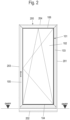
- Figure 1a shows a perspective view of a window 1 with a frame 200 and a sash 100 arranged thereon with one or more fittings (not shown here) so as to be movable, in particular rotatable and/or tiltable.
- the sash 100 preferably has a sash frame 101 in which a surface element 102 is fixed - in particular adhesively attached.
- the sash frame 101 has four angled, Fig. 1a each at right angles to one another as rectangular frame beams 103 to 106, to which the surface element 102 is fixed.
- the surface element 102 can be designed, for example, as a glass pane, in particular as an insulating glass pane. However, it can also be designed as a metal plate or plastic plate. In the context of the implementation of the present invention, the design as an insulating glass pane is particularly preferred, with the frame being designed as the sash of a window or - in the context of the description of the figures, a synonymous term for a door.
- the invention is preferably designed on a so-called door window.
- This is an element in which at least one sash frame 101, which is also closed around the perimeter, is arranged on a peripherally closed frame 200 so that it can rotate and/or tilt in the manner of a window.
- door window a lower frame beam 202 of the frame 200 of the window 1 is designed in the manner of a floor threshold and can also be used as a step threshold or profile ( Fig. 2).
- Fig. 2 represents the usual installation position that window 1 takes on a building or in a building opening.
- the door is aligned vertically (XZ plane) and the vertical lower frame member 202 of the frame 200 is also the vertical lower frame member 202 of the frame 200 at the installation location on the building and the vertical lower frame member 104 of the casement frame 101 is also the lower vertical frame member 104 of the casement frame 100 at the installation location on the building.
- the frame members 103 to 106 of the sash frame 101 and the frame members of the frame 200 are designed as so-called composite profiles and have at least one metal shell and at least one insulating web zone (which is explained below by way of example) or have several metal profile zones and/or several insulating zones made of insulating webs or elements analogous thereto.
- the casement frame 101 can initially have "identical" frame members 103, 104, 105, 106 all around in terms of cross-section, all of which are mitred and assembled to form the casement frame 101.
- the lower frame member 104 of the casement frame 101 then additionally has a projection or projection profile 110 towards the bottom ( Fig.2 ), which accommodates at least one functional element, for example a floor seal (not shown) and thus fills a gap between the outer edge of the actual composite profile of the lower sash frame beam 104 and the upper edge of the horizontally lower frame beam 202.
- the frame 200 also has a circumferentially closed frame, which is preferably composed of four frame beams 201, 202, 203, 204.
- the frame 200 has an upper horizontal frame beam 204 and two vertical frame beams 201, 203.
- a lower horizontal frame beam 202 is also provided. It is connected or attached to the vertical frame beams 201, 203 at an obtuse right angle.
- the horizontal upper frame beams 204, 106 and the vertical frame beams 201, 203 and 104, 106 can have the same cross-section. They can then be easily mitred and thus easily connected.
- the window 1 is designed as a door window and can be used or installed in a building opening in such a way that the lower frame member 202 of the frame 200 is also used as a type of tread profile, so that its upper side can be designed or installed flush with the surrounding floor area, the vertically lower frame members 202, 104 are preferably constructed differently and realize more functions than the other frame members.
- the abbreviation "OKFF” ( O berkante Fertigfußêt ) in Fig.2 indicates the top of the surrounding floor area of the window 1.
- the lower frame member 202 of the frame 200 is below this level, so that the top of the lower horizontal frame member 202 is at the OKFF level.
- the abbreviation “OKFF” also indicates the top of the surrounding floor area of the window 1 in the other figures.
- fittings are required for the movable mounting of the sash or sash frame 101 on the frame 200. These fittings are arranged at various points between the frame 200 and the sash frame 101. They are not shown here.
- the fittings implement at least one rotation function in order to be able to open the sash 100 about a vertical axis of rotation.
- the fittings can also implement a tilt function in order to be able to pivot the sash 100 into a tilt position about a lower horizontal axis of rotation provided in the lower area of the window 1.
- the sash 100 extends in an X/Y plane. Perpendicular to the image plane, the Z direction extends perpendicular to the main plane - the X/Y plane - of the window sash (see also Fig.2 ).
- the frame beams 103 - 106 and 201 to 204 each have a main direction of extension in which they run. In the case of light metal profiles, this is usually a direction in which the light metal profiles are manufactured, which can be done by extrusion, for example.
- the frame beams 103 to 106 are assembled to form a sash frame 101 with a rectangular shape. This is a particularly preferred embodiment, but not a mandatory embodiment.
- the frame 200 also has a circumferentially closed frame. This has a lower horizontal frame beam 202, an upper horizontal frame beam 204 and two vertical frame beams 201, 203 which can have the same cross-section and can be mitred together.
- the window 1 again has only one frame 200, but two wings 100, 100'.
- the first wing 100 is a so-called active wing and the second wing 100' is a so-called passive wing.
- the active wing 100 is the wing that opens first and the passive wing 100' is the wing that opens last of this double-winged window 1, which can normally remain closed, since ventilation or the like can take place via the active wing 100.
- the passive wing 100' is therefore only opened in exceptional cases, for example if bulky objects are to be transported through a correspondingly large window opening.
- the passive leaf 100' is usually designed analogously to the active leaf 100. In this respect, it can also have several leaf frame beams 103', 104', 105', 106', which are connected to form a leaf frame 101', as well as a surface element 102', which is inserted into the leaf frame 101'.
- Fig. 3b it is shown that it is intended that the passive leaf 100' is fixed and locked to the frame 200 with a lower rebate bolt 107' - and preferably with an upper rebate bolt not shown here.
- the rebate drive bolt 107' is movable by a locking bar fitting 108' of the inactive leaf 100'.
- the rebate drive bolt 107' is guided in a locking guide piece 109' of the inactive leaf 100'.
- the rebate drive bolt 107', the locking bar fitting 108' and the locking guide piece 109' can be arranged concealed in a vertical rebate space so that these elements are not visible.
- the active leaf 100 can also have a lower rebate bolt 107 and preferably an upper rebate bolt (not shown here) with which the active leaf 100 is fixed and locked to the frame 200.
- the rebate bolt 107 of the active leaf 100 can also be movable by a locking bar fitting 108 of the active leaf 100.
- the rebate bolt 107 of the active leaf 100 is guided in a locking guide piece 109 of the active leaf 101.
- the rebate bolt 107, the locking bar fitting 108 and the locking guide piece 109 can also be arranged concealed in a vertical rebate space in the active leaf 100, so that these elements are not visible.
- the respective rebate bolt 107, 107' can be moved over the lower horizontal plane (XY plane to Fig. 1b ) of the respective wing 100, 100' vertically - i.e. in negative Z-direction to Fig. 1b - be moved out so that, in a closed state of the respective wing 100, 100', it engages in a corresponding recess in the lower horizontal frame member 202 of the frame 200.
- the term "closed state" of the sash 100, 100' is to be understood as the state of the sash 100, 100' in which the rebate bolt 107, 107' of the sash 100, 100' engages in the opening provided for it in the frame 200 or in a strike plate 318 that is fastened to/in the frame 200.
- the passive leaf 100' is initially activated by a leaf stop and support device 300 shortly before reaching the closed state and then runs onto it in the closed state, the leaf stop and support device 300 being designed to stop the rotary movement of the passive leaf 100' and to slightly raise the passive leaf 100' so that the lower corner of the passive leaf 100' facing away from the rotary fitting is firmly supported in the closed state.
- the leaf stop and support device 300 can be designed on a single-leaf window 1, but it can also be designed on a double-leaf window 1.
- the sash stop and support device 300 is preferably formed on the inactive sash 100'.
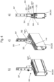
- the wing stop and support device 300 is here - as in Fig. 3b and Fig. 3c shown - arranged on the bolt guide piece 109' of the rebate bolt 107' of the passive leaf 100'.
- a pin 301 is attached to the wing stop and support device 300, which extends in the horizontal direction - i.e. in the X direction - Fig. 1b - extends.
- the pin may have a roller 302 at its free end, as shown in Fig. 3c This is advantageous because it minimizes friction and wear, but it is not mandatory.
- the pin 301 engages in a corresponding pocket that is formed on the bolt guide piece 108 of the active leaf 100. This advantageously stiffens the active leaf 100 in its closed state, so that subsequent locking by the locking bar fitting 108 and the rebate bolt 107 can take place securely.
- the pocket runs onto the roller 302, which slightly lifts the active leaf 100. This advantageously relieves the frame of the active leaf 100 against warping.
- a reverse arrangement is also conceivable, so that the roller 302 is attached to the active leaf 100 and the pocket is arranged on the inactive leaf 100'.
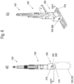
- the wing stop and support device 300 is in Fig. 4a to Fig. 4c with the lower horizontal frame beam 202 of the frame 200 without any further components.
- Fig. 4a the wing stop and support device 300 is shown in a full section.
- the wing stop and support device 300 according to Fig. 4a to Fig. 4c has a housing 303, in the interior 304 of which a support bracket and stop 305 with a tilt lever-like geometry is pivotally mounted on an axis 306.
- the support bracket and stop 305 fulfills two functions: It serves the passive leaf 100' as a stop, which becomes active when the passive leaf 100' has reached its closed state, and as a support bracket, by means of which the passive leaf 100' is slightly raised shortly before it has reached its closed state.
- the housing 303 is attached to a strip 307.
- the housing 303 is attached to the inactive leaf 100' via the strip 307.
- the housing 303 also has a vertically downward-facing opening 308.
- the rocker arm-like geometry of the support bracket and stop 305 is divided into a support cam 309 and a counter bearing cam 310 as well as a bearing section 311 with a bore through which the axis 306 passes.
- the support bracket and stop 305 are preferably designed as one piece.
- the counter bearing cam 310 is supported in a support and stop position of the support bracket and stop 305 on a counter bearing 312, as shown in Fig. 4a
- the support cam 309 is supported in a basic position of the support block and stop 305 on the counter bearing 312, as shown in Fig. 5a is shown.
- the support cam 309 together with the bearing section 311, closes the opening 308 of the housing 303, so that the support block and stop 305 do not protrude beyond the outer contour of the housing 303.
- the counter bearing 312 preferably has a cylindrical geometry and passes through the interior 304 of the housing 303 and is inserted into the housing 303 at its two free ends and fixed in the axial direction, e.g. by a press fit in the housing 303.
- the support block and stop 305 is provided with a recess 313 that includes the counter bearing cam 310 and the bearing section 311.
- the recess 313 serves to accommodate a return spring 314.
- the return spring 314 is preferably designed as a space-saving leg spring that is arranged around the axis 306 or pushed onto the axis 306 and passes through the recess 313.
- a first leg of the return spring 314 is supported on the recess 313 of the support block and stop 305, while a second leg of the return spring 314 is supported in a bore 315 that is made in the housing 303.
- the support block and stop 305 is preferably movable by a magnetic operating principle.
- the support block and stop 305 can thus be movable, for example, by a permanent magnet or by an electromagnet and is preferably made of a ferromagnetic material.
- the return spring 314 is used to return the support block and stop 305 from the support and stop position - as in Fig. 4a shown- in a basic position -as in Fig. 5a shown- intended.
- the wing stop and support device 300 can have an abutment 316. This can preferably be designed to be height-adjustable, but is at a preset height during opening and closing of the passive wing 100'
- the abutment 316 is designed according to Fig. 4a - c and Fig. 5a -g inserted into the lower horizontal frame member 202 of the frame 200.
- the support cam 309 of the support bracket and stop 305 engages in the abutment 316 in its support and stop position.
- a pivot drive means 317 is required for pivoting the support block and stop 305 in order to move the support block and stop 305 from its basic position into the support and stop position shortly before the closed state of the inactive leaf 100' is reached.
- the pivot drive means 317 is formed here by a permanent magnet, in particular by a neodymium magnet.
- the pivot drive means 317 pivots the support block and stop 305 from the basic position of the support block and stop 305, in which the support cam 309 is aligned horizontally, to the support and stop position of the support block and stop 305, in which the support cam 309 is aligned vertically and the support cam 309 engages the abutment 316.
- the inactive leaf 100' Due to the kinetic energy of the inactive leaf 100', the inactive leaf 100' is slightly raised when the support bracket and stop 305 is moved into the vertical position of the support cam 309 or into the support and stop position of the support bracket and stop 305, which raises the freely projecting part of the inactive leaf 100' - i.e. Fig. 3a the lower right corner of the passive leaf 100' of window 1 is relieved and thus warping of the passive leaf 100' is prevented.
- the abutment 316, the pivot drive means 317 and the recesses into which the rebate bolts 107, 107' engage can be combined in the locking plate 318, which is inserted in the lower horizontal frame beam 202 of the frame 200, as shown in Fig. 3c , Fig. 4a - c as well as Fig. 5a - g is shown.
- Fig. 5a - g the approach process of the passive leaf 100' into its closed state and the reaching of the closed state as well as the associated pivoting process of the support bracket and stop 305 is shown, in which the support cam 309 is brought from its horizontal basic position into its vertical support and stop position.
- the pivot drive means 317 is designed such that it pivots the support block and stop 305 out of its basic position against the resistance of the return spring 314.
- Fig. 5a the inactive leaf 100' is shown approaching its closed state.
- the support bracket and stop 305 is in its basic position, in which the support cam 309 of the support bracket and stop 305 is aligned horizontally and the opening 308 of the housing 303 is closed as a result.
- the counter bearing cam 310 of the support bracket and stop 305 is supported on one side of the interior 304 of the housing 303.
- the support bracket and stop 305 is held in this position by the force of the return spring 314.
- Fig. 5b is shown how the inactive leaf 100' continues to approach its closed state.
- the pivot drive means 317 passes through the support bracket and stop 305, the support bracket and stop 305 leaves its basic position due to the magnetic field acting on it - the force of which overcomes the opposing force of the return spring 314 - and is set in a pivoting movement so that the support cam 309 leaves its horizontal position.
- Fig. 5c it is shown how the inactive leaf 100' continues to approach its closed state.
- the support cam 309 of the support bracket and stop 305 has slid along the pivot drive means 317 with a rounded edge 319 due to the magnetic field acting on it, in order to then engage in a recess 320 formed by the abutment 316 while continuing its pivoting movement, which is delimited by a support surface 321 of the abutment 316 as well as a first wall 322 and a second wall 323.
- the abutment 316 is preferably designed as a type of threaded pin or bolt and is inserted into a corresponding bore which has a nut thread at least over a partial length.
- the bore can be longer than the abutment 316, so that the recess 320 is formed by the abutment 316 not filling the bore over its entire length.
- the first wall 322 and the second wall 323 are thus formed by the bore.
- the wing stop and support device 300 thus works according to the positive locking principle.
- Positive locking in the sense of this document means that one connection partner is in the way of the other.
- the positive locking is also achieved solely by an opening movement of the The passive leaf is automatically released again after 100', ie no manual unlocking is required, e.g. by a user of the door.
- the first wall 322 of the recess 320 is closer to the pivot drive means 317 than the second wall 323.
- the continued pivoting movement of the support block and stop 305 is made possible by the magnetic field of the pivot drive means 317 which still acts on the support block and stop 305, in particular on its support cam 309.
- Fig. 5d is shown how the inactive leaf 100' continues to approach its closed state.
- the support cam 309 of the support bracket and stop 305 makes contact via the rounded edge 319 with the support surface 321 of the recess 320, which forms the abutment 316.
- Fig. 5e it is shown how the inactive leaf 100' continues to approach its closed state.
- the support cam 309 of the support bracket and stop 305 as it continues its pivoting movement, rolling over the rounded edge 319, now has surface contact with the support surface 321 of the recess 320 of the abutment 316 via a surface 324 at its free end, so that the support cam 309 is now aligned vertically and the counter bearing cam 310 of the support bracket and stop 305 is supported on the counter bearing 312.
- the freely projecting part of the inactive leaf 100' is raised slightly and is thus advantageously protected against warping.
- the abutment 316 is equipped with a height adjustment device by means of which the support surface 321 can be adjusted in height.
- the abutment 316 is preferably height-adjustable by means of a thread. This allows the amount by which the cantilevered part of the 100' passive leaf is raised to be adjusted easily, quickly and with high accuracy.
- Fig. 5f is shown how the inactive leaf 100' has almost reached its closed state. Due to its kinetic energy, the inactive leaf 100' slides with a freely projecting end slightly raised in the vertical direction over the surface 324 at the free end of the support cam 309 on the support surface 321 of the abutment 316.
- Fig. 5g it is shown that the inactive leaf 100' has reached its closed state.
- the support cam 309 of the support bracket and stop 305 has, while continuing its sliding movement, in which it slides with its surface 324 at its free end over the support surface 321 of the abutment 316, the second wall 323, which serves as a stop for the support cam 309 of the support bracket and stop 305 and thus also for the passive leaf 100'.
- a variant of the invention is described in the Figures 6a, b and 7a - d shown.
- the abutment 316 is formed in the passive leaf 101' and the movable support cam 309 is arranged on or in the lower horizontal frame member 202 of the frame 200.
- the support bracket and stop 305 can be housed in a separate locking plate 318, as shown in Fig. 6a , b.
- the support block and stop 305 can also be housed directly - i.e. without the locking plate 318 - in the lower horizontal frame beam 202 of the frame 200.
- the function of the support block and stop 305 is analogous to that shown in the Figures 4a - c and 5a - g , as in Figure 7a - d is shown.
- Fig. 7a the support bracket and stop 305 is shown in its basic position.
- the support cam 309 is in the basic position of the support bracket and stop 305 in a first recess 325 provided for this purpose in the strike plate 318 or in the lower horizontal frame beam 202 of the frame 200. This means that the accessibility of the lower horizontal frame beam 202 is fully maintained.
- the support bracket and stop 305 also has Fig. 6a and 6b as well as Fig 7a - d the cylindrical bearing section 311.
- the counter bearing section 310 is not required here and is therefore not designed here.
- the support block and stop 305 according to Fig.
- the bearing function takes place on the outer circumference of the bearing section 311, so that the bore in the bearing section 311 can be omitted here.
- the bearing section 311 engages in a further, second recess 326, wherein the closing plate 318 forms a metallic cover in the vertical direction, so that a bearing is formed.
- the return spring 314 can also be omitted here because the support cam 309 of the support bracket and stop 305 returns to its basic position due to the force of gravity acting on it when the passive leaf 100' is opened and the support cam is no longer in the effective range of the pivot drive means 317.
- the pivot drive means 317 which is also preferably designed as a permanent magnet here, forces the support block and stop 305 with its support cam 309 from its basic position into a pivoting movement, as shown in Fig. 7b -analogous to Fig. 5b - is shown.
- a rounded edge 319 slides along the pivot drive means 317, in order to then engage, while continuing its pivoting movement, in a recess 320 formed by the abutment 316, which is delimited by the support surface 321 as well as the first wall 322 and a second wall 323, as shown in Fig. 7b and 7c is shown.
- Fig. 7d it is shown how the inactive leaf 100' continues to approach its closed state.
- the support cam 309 of the support bracket and stop 305 as it continues its pivoting movement, rolling over the rounded edge 319, now has surface contact with the support surface 321 of the recess 320 of the abutment 316 via a surface 324 at its free end, so that the support cam 309 is now aligned vertically.
- the freely projecting part of the inactive leaf 100' is raised slightly and is thus advantageously protected against warping.
- the abutment 316 is equipped with a height adjustment device by means of which the support surface 321 can be adjusted in height.
- the abutment 316 is preferably height-adjustable by means of a thread. This allows the amount by which the freely projecting part of the inactive leaf 100' is raised to be set easily, quickly and with high precision.
- the sash stop and support device 300 is designed here on a double-sash window 1. However, it can also be designed on a single-sash window 1. In a double-sash window 1, it is preferably designed on the inactive sash 100' or acts on the inactive sash 100'. However, it can also be designed on the active sash 100 or act on the active sash 100.
- the sash stop and support device 300 therefore has a number of advantages. Due to its simple design, which is limited to just a few components, it enables a permanently safe function and is very compact. Furthermore, it creates a stable and safe support as well as a safe and precise stop and does not require costly electrical actuators and drives. Furthermore, The sash stop and support device 300 does not impede or compromise the accessibility of window 1 when sash 100, 100' is open.
Landscapes
- Engineering & Computer Science (AREA)
- Civil Engineering (AREA)
- Structural Engineering (AREA)
- Mechanical Engineering (AREA)
- Wing Frames And Configurations (AREA)
Claims (18)
- Fenêtre (1), en particulier porte-fenêtre, aveca. un châssis dormant (200) et au moins un vantail (100, 101') pouvant être fixé à celui-ci de façon pivotante,b. qui comporte au moins un châssis de vantail (101, 101'), lequel châssis de vantail (101, 101') accueille un élément plat (102, 102') et lequel châssis de vantail (101, 101') se compose de plusieurs montants et traverses de châssis de vantail (103 -106, 103' - 106'), etc. avec des ferrures pour déplacer le vantail (100, 100') dans un mouvement pivotant par rapport au châssis dormant (200) vers un état ouvert et un état fermé,d. une crémone mobile (107, 107') étant de préférence prévue pour verrouiller le vantail (100, 100') dans l'état fermé, laquelle peut se déplacer dans le châssis dormant (200), en particulier dans une gâche (318) fixée dans ou sur le châssis dormant (200), et qui s'y engage,e. et au moins un dispositif d'arrêt et d'appui du vantail (300) conçu pour arrêter un mouvement pivotant du vantail (100, 100'),f. lequel dispositif d'arrêt et d'appui du vantail (300) présente un palier d'appui et butée (305) pouvant être déplacé par un moyen d'entraînement pivotant magnétique (317) avec une came d'appui (309) sur le vantail (100, 101') ou le châssis dormant (200) et un contre-appui (316) sur le châssis dormant (200) ou le vantail (100, 100'), dans lequel la came d'appui (309) s'engage au moins quand le vantail est fermé,caractérisée en ce que
g. le dispositif d'arrêt et d'appui du vantail (300) est en outre conçu pour soulever le vantail (100, 100') de telle manière qu'un coin du vantail (100, 100') opposé à la ferrure pivotante soit fixé et soutenu dans l'état fermé. - Fenêtre (1) selon la revendication 1, caractérisée en ce que le vantail (100, 100') est fixé de façon basculante sur le châssis dormant (200) et comporte des ferrures pour déplacer le vantail (100, 100') dans un mouvement basculant par rapport au châssis dormant (200) et/ou en ce que la fenêtre (1) comporte deux vantaux (100, 100'), dont un vantail (100, 100') conçu comme un vantail mobile (100) et un autre comme un vantail fixe (100'), au moins un des vantaux, en particulier le vantail fixe, pouvant comporter le dispositif d'arrêt et d'appui du vantail (300) et l'autre vantail, en particulier le vantail mobile, pouvant comporter facultativement un dispositif d'arrêt et d'appui du vantail (300) ou en être dépourvu.
- Fenêtre (1) selon l'une des revendications précédentes, caractérisée en ce que les deux vantaux (100, 100') présentent chacun une crémone (107, 107').
- Fenêtre (1) selon l'une des revendications précédentes, caractérisée en ce que le contre-appui (316) est réglable en hauteur, de préférence de telle sorte que le contre-appui (316) peut être réglé en hauteur à l'aide d'un filetage et est conformé comme une sorte de tige filetée ou de boulon fileté et inséré dans un alésage correspondant qui présente un filetage d'écrou sur au moins une partie de la longueur.
- Fenêtre (1) selon l'une des revendications précédentes, caractérisée en ce que le dispositif d'arrêt et d'appui du vantail (300) est disposé sur un guide de crémone (109, 109') de la crémone (107, 107') du vantail (100, 100') correspondant.
- Fenêtre (1) selon l'une des revendications précédentes, caractérisée en ce que le dispositif d'arrêt et d'appui du vantail (300) fonctionne selon un principe d'engagement positif, dans lequel l'engagement positif n'est levé automatiquement que par un mouvement d'ouverture du vantail (100, 100').
- Fenêtre (1) selon l'une des revendications précédentes, caractérisée en ce qu'un appui supplémentaire est ménagé sur le dispositif d'arrêt et d'appui du vantail (300) pour soulever aussi légèrement le coin extérieur du bas du vantail (100, 100') sans dispositif d'arrêt et d'appui du vantail (300) dans l'état ouvert afin de décharger celui-ci, l'appui supplémentaire étant de préférence réalisé de telle sorte qu'un goujon (301) muni d'un galet (302) à son extrémité libre est fixé sur le dispositif d'arrêt et d'appui du vantail (300) et s'étend dans le sens horizontal, une poche du vantail (100, 100') sans dispositif d'arrêt et d'appui du vantail (300) passant par-dessus le galet (302) lors de la fermeture du vantail (100, 100') sans dispositif d'arrêt et d'appui du vantail (300).
- Fenêtre (1) selon l'une des revendications précédentes, caractérisée en ce que le dispositif d'arrêt et d'appui du vantail (300) présente un boîtier (303) qui est fixé sur un bandeau (307) et un palier d'appui et butée (305) est supporté dans l'espace intérieur (304) du boîtier (303) de façon pivotante sur un axe (306) et le boîtier (303) présente une ouverture (308) orientée verticalement vers le bas, le palier d'appui et butée (305) étant de préférence réalisé d'une pièce et pouvant être déplacé par un principe d'action magnétique.
- Fenêtre (1) selon l'une des revendications précédentes, caractérisée en ce que la géométrie du palier d'appui et butée (305) se décompose au moins en la came d'appui (309) et une partie de palier (311), la partie de palier (311) s'engageant de préférence dans un deuxième évidement (326) plus large, une couverture métallique étant formée dans le sens vertical de façon à former un palier.
- Fenêtre (1) selon l'une des revendications précédentes, caractérisée en ce que le palier d'appui et butée (305) présente une came de contre-appui (310) qui s'appuie de préférence sur un contre-appui (312) dans une position d'appui et de butée du palier d'appui et butée (305).
- Fenêtre (1) selon l'une des revendications précédentes, caractérisée en ce que la came d'appui (309) s'appuie sur le contre-appui (312) dans une position de base du palier d'appui et butée (305) et la came d'appui (309) ferme alors l'ouverture (308) du boîtier (303) avec la partie de palier (311), de sorte que le palier d'appui et butée (305) ne dépasse pas du contour extérieur du boîtier (303).
- Fenêtre (1) selon l'une des revendications précédentes, caractérisée en ce que la came d'appui (309) repose, dans la position de base du palier d'appui et butée (305), dans un premier évidement (325) prévu à cette fin dans la gâche (318) ou dans la traverse de châssis inférieure (202) du châssis dormant (200) et/ou en ce que la came d'appui (309) du palier d'appui et butée (305) présente une arête arrondie (319).
- Fenêtre (1) selon l'une des revendications précédentes, caractérisée en ce que le palier d'appui et butée (305) est muni d'un évidement (313) qui entoure la came de contre-appui (310) ainsi que la partie de palier (311) et qui sert à recevoir un ressort de rappel (314).
- Fenêtre (1) selon l'une des revendications précédentes, caractérisée en ce que le moyen d'entraînement pivotant (317) est formé par un aimant permanent, en particulier un aimant au néodyme, ou par un électroaimant et/ou en ce que le moyen d'entraînement pivotant (317) est conçu de telle sorte qu'il fait sortir le palier d'appui et butée (305) de sa position de base contre la résistance du ressort de rappel (314).
- Fenêtre (1) selon l'une des revendications précédentes, caractérisée en ce que le contre-appui (316), le moyen d'entraînement pivotant (317) et des évidements dans lesquels les crémones (107, 107') s'engagent sont réunis dans une gâche (318) qui est insérée dans la traverse de châssis inférieure (202) du châssis dormant (200).
- Fenêtre (1) selon l'une des revendications précédentes, caractérisée en ce que le contre-appui (316) forme un creux (320) qui est délimité par une surface d'appui (321) du contre-appui (316) et par une première paroi (322) et une deuxième paroi (323) et/ou en ce que le contre-appui (316) est intégré avec le creux (320) et le moyen d'entraînement pivotant (317) dans le guide de crémone (109, 109') de la crémone (107, 107') du vantail (100, 100').
- Fenêtre (1) selon la revendication 16, caractérisée en ce que la première paroi (322) du creux (320) est plus proche du moyen d'entraînement pivotant (317) que la deuxième paroi (323).
- Fenêtre (1) selon l'une des revendications précédentes, caractérisée en ce que la came d'appui (309) du palier d'appui et butée (305) vient en contact, quand le vantail (100, 100') est fermé, avec la deuxième paroi (323) qui sert de butée pour la came d'appui (309) du palier d'appui et butée (305) et ainsi pour le vantail fixe (100').
Priority Applications (1)
| Application Number | Priority Date | Filing Date | Title |
|---|---|---|---|
| HRP20241043TT HRP20241043T1 (hr) | 2021-09-27 | 2022-09-26 | Prozor |
Applications Claiming Priority (1)
| Application Number | Priority Date | Filing Date | Title |
|---|---|---|---|
| DE202021105180.9U DE202021105180U1 (de) | 2021-09-27 | 2021-09-27 | Fenster |
Publications (2)
| Publication Number | Publication Date |
|---|---|
| EP4155497A1 EP4155497A1 (fr) | 2023-03-29 |
| EP4155497B1 true EP4155497B1 (fr) | 2024-05-29 |
Family
ID=78509412
Family Applications (1)
| Application Number | Title | Priority Date | Filing Date |
|---|---|---|---|
| EP22197766.3A Active EP4155497B1 (fr) | 2021-09-27 | 2022-09-26 | Fenêtre |
Country Status (8)
| Country | Link |
|---|---|
| EP (1) | EP4155497B1 (fr) |
| DE (1) | DE202021105180U1 (fr) |
| DK (1) | DK4155497T3 (fr) |
| ES (1) | ES2986074T3 (fr) |
| FI (1) | FI4155497T3 (fr) |
| HR (1) | HRP20241043T1 (fr) |
| PL (1) | PL4155497T3 (fr) |
| PT (1) | PT4155497T (fr) |
Families Citing this family (1)
| Publication number | Priority date | Publication date | Assignee | Title |
|---|---|---|---|---|
| DE102022209162A1 (de) * | 2022-09-02 | 2024-03-07 | Aug. Winkhaus Gmbh & Co. Kg | Beschlag für einen gegen einen Rahmen schwenkbaren Flügel |
Family Cites Families (4)
| Publication number | Priority date | Publication date | Assignee | Title |
|---|---|---|---|---|
| DE7108080U (de) | 1971-05-19 | Fortmeier J | Feststellvorrichtung fur geöffnete Türen | |
| FR3069008B1 (fr) * | 2017-07-17 | 2020-12-18 | Somfy Activites Sa | Fenetre coulissante pour un batiment et installation domotique comprenant une telle fenetre coulissante, ainsi que procede de commande associe |
| DE102018112430A1 (de) | 2018-05-24 | 2019-11-28 | SCHÜCO International KG | Fenster |
| DE202020106255U1 (de) * | 2020-11-02 | 2020-11-09 | Grundmeier Kg | Doppelflügelige Tür |
-
2021
- 2021-09-27 DE DE202021105180.9U patent/DE202021105180U1/de active Active
-
2022
- 2022-09-26 EP EP22197766.3A patent/EP4155497B1/fr active Active
- 2022-09-26 HR HRP20241043TT patent/HRP20241043T1/hr unknown
- 2022-09-26 ES ES22197766T patent/ES2986074T3/es active Active
- 2022-09-26 PL PL22197766.3T patent/PL4155497T3/pl unknown
- 2022-09-26 PT PT221977663T patent/PT4155497T/pt unknown
- 2022-09-26 FI FIEP22197766.3T patent/FI4155497T3/fi active
- 2022-09-26 DK DK22197766.3T patent/DK4155497T3/da active
Also Published As
| Publication number | Publication date |
|---|---|
| DK4155497T3 (da) | 2024-08-19 |
| ES2986074T3 (es) | 2024-11-08 |
| EP4155497A1 (fr) | 2023-03-29 |
| HRP20241043T1 (hr) | 2024-11-08 |
| PT4155497T (pt) | 2024-08-14 |
| PL4155497T3 (pl) | 2024-11-04 |
| DE202021105180U1 (de) | 2021-10-26 |
| FI4155497T3 (fi) | 2024-08-30 |
Similar Documents
| Publication | Publication Date | Title |
|---|---|---|
| EP3102759B1 (fr) | Ferrure d'un battant de fenêtres ou de portes, au moins relevable et coulissant | |
| EP3622139B1 (fr) | Fenêtre ou porte à limitation d'ouverture en basculement anti-effraction | |
| EP4473182A1 (fr) | Agencement de profilé d'une fenêtre ou d'une porte ayant un profilé de châssis/battant, en particulier un profilé de châssis/battant coulissant | |
| DE202008012837U1 (de) | Fenster mit verriegelbarem Beschlag | |
| EP4473180B1 (fr) | Dispositif de décalage pour le décalage forcé d'un vantail, en particulier d'un vantail coulissant, d'une fenêtre ou d'une porte | |
| WO2024037764A1 (fr) | Ensemble profilé d'une fenêtre ou d'une porte présentant un profilé de châssis/battant, en particulier un profilé de châssis/battant coulissant | |
| EP4473179B1 (fr) | Dispositif de déplacement pour le déplacement forcé d'un battant, en particulier d'un battant coulissant, d'une fenêtre ou d'une porte | |
| DE20118906U1 (de) | Sperr- und Sicherungsvorrichtung für einen Flügel einer Hebe- und Schiebetür und/oder eines Hebe- und Schiebefensters, Treibstangenbeschlag für eine Hebe- und Schiebetür und/oder ein Hebe- und Schiebefenster sowie Hebe- und Schiebetür oder -Fenster mit einer derartigen Sperr- und Sicherungsvorrichtung | |
| EP3372765B1 (fr) | Armature et séparation de douche | |
| EP1266115B1 (fr) | Unite ferrure pour une fenetre ou une porte | |
| EP4155497A1 (fr) | Fenêtre | |
| EP2149661B1 (fr) | Fermeture de bâtiment résistante aux explosions et à l'effraction | |
| DE202013008784U1 (de) | Beschlag eines zumindest hebbaren, vorzugsweise aber auch verschiebbaren Flügels von Fenstern oder Türen | |
| EP0572988B1 (fr) | Gâche | |
| EP4573251A1 (fr) | Dispositif de décalage permettant le décalage forcé d'un battant, en particulier d'un battant coulissant, d'une fenêtre ou d'une porte | |
| EP4105416A1 (fr) | Dispositif de blocage pour une porte bâtie de deux côtés | |
| EP0380059A2 (fr) | Verrouillage du coin d'une porte ou fenêtre | |
| DE4236431C2 (de) | Verriegelungsbeschlag für Fenster oder Türen | |
| EP3613929A1 (fr) | Ferrure destinée à être installée entre un battant et un cadre fixe de fenêtre, porte ou analogue ainsi que fenêtre, porte ou analogue dotée d'une telle ferrure | |
| EP4063602B1 (fr) | Fenêtre oscillante basculante ou porte oscillante basculante pourvue de palier libre inférieur | |
| EP0887501A2 (fr) | Ferrure arrangée en feuillure pour fenêtre, porte ou similaire | |
| WO2024240450A1 (fr) | Dispositif de décalage pour le décalage forcé d'un battant, en particulier d'un battant coulissant, d'une fenêtre ou d'une porte | |
| EP2952657B1 (fr) | Dispositif de porte coulissante | |
| DE102017007613B4 (de) | Ladensystem für Gebäudeöffnungen | |
| EP1780359A2 (fr) | Dispositif de levage du battant pour ferrure de crémone |
Legal Events
| Date | Code | Title | Description |
|---|---|---|---|
| REG | Reference to a national code |
Ref country code: HR Ref legal event code: TUEP Ref document number: P20241043T Country of ref document: HR |
|
| PUAI | Public reference made under article 153(3) epc to a published international application that has entered the european phase |
Free format text: ORIGINAL CODE: 0009012 |
|
| STAA | Information on the status of an ep patent application or granted ep patent |
Free format text: STATUS: THE APPLICATION HAS BEEN PUBLISHED |
|
| AK | Designated contracting states |
Kind code of ref document: A1 Designated state(s): AL AT BE BG CH CY CZ DE DK EE ES FI FR GB GR HR HU IE IS IT LI LT LU LV MC MK MT NL NO PL PT RO RS SE SI SK SM TR |
|
| STAA | Information on the status of an ep patent application or granted ep patent |
Free format text: STATUS: REQUEST FOR EXAMINATION WAS MADE |
|
| 17P | Request for examination filed |
Effective date: 20230926 |
|
| RBV | Designated contracting states (corrected) |
Designated state(s): AL AT BE BG CH CY CZ DE DK EE ES FI FR GB GR HR HU IE IS IT LI LT LU LV MC MK MT NL NO PL PT RO RS SE SI SK SM TR |
|
| GRAP | Despatch of communication of intention to grant a patent |
Free format text: ORIGINAL CODE: EPIDOSNIGR1 |
|
| STAA | Information on the status of an ep patent application or granted ep patent |
Free format text: STATUS: GRANT OF PATENT IS INTENDED |
|
| INTG | Intention to grant announced |
Effective date: 20231205 |
|
| P01 | Opt-out of the competence of the unified patent court (upc) registered |
Effective date: 20231221 |
|
| GRAS | Grant fee paid |
Free format text: ORIGINAL CODE: EPIDOSNIGR3 |
|
| GRAJ | Information related to disapproval of communication of intention to grant by the applicant or resumption of examination proceedings by the epo deleted |
Free format text: ORIGINAL CODE: EPIDOSDIGR1 |
|
| GRAL | Information related to payment of fee for publishing/printing deleted |
Free format text: ORIGINAL CODE: EPIDOSDIGR3 |
|
| STAA | Information on the status of an ep patent application or granted ep patent |
Free format text: STATUS: REQUEST FOR EXAMINATION WAS MADE |
|
| GRAP | Despatch of communication of intention to grant a patent |
Free format text: ORIGINAL CODE: EPIDOSNIGR1 |
|
| STAA | Information on the status of an ep patent application or granted ep patent |
Free format text: STATUS: GRANT OF PATENT IS INTENDED |
|
| GRAS | Grant fee paid |
Free format text: ORIGINAL CODE: EPIDOSNIGR3 |
|
| INTC | Intention to grant announced (deleted) | ||
| GRAA | (expected) grant |
Free format text: ORIGINAL CODE: 0009210 |
|
| STAA | Information on the status of an ep patent application or granted ep patent |
Free format text: STATUS: THE PATENT HAS BEEN GRANTED |
|
| INTG | Intention to grant announced |
Effective date: 20240411 |
|
| AK | Designated contracting states |
Kind code of ref document: B1 Designated state(s): AL AT BE BG CH CY CZ DE DK EE ES FI FR GB GR HR HU IE IS IT LI LT LU LV MC MK MT NL NO PL PT RO RS SE SI SK SM TR |
|
| REG | Reference to a national code |
Ref country code: CH Ref legal event code: EP |
|
| REG | Reference to a national code |
Ref country code: IE Ref legal event code: FG4D Free format text: LANGUAGE OF EP DOCUMENT: GERMAN |
|
| REG | Reference to a national code |
Ref country code: DE Ref legal event code: R096 Ref document number: 502022000965 Country of ref document: DE |
|
| REG | Reference to a national code |
Ref country code: PT Ref legal event code: SC4A Ref document number: 4155497 Country of ref document: PT Date of ref document: 20240814 Kind code of ref document: T Free format text: AVAILABILITY OF NATIONAL TRANSLATION Effective date: 20240807 |
|
| REG | Reference to a national code |
Ref country code: DK Ref legal event code: T3 Effective date: 20240815 |
|
| REG | Reference to a national code |
Ref country code: NL Ref legal event code: FP |
|
| REG | Reference to a national code |
Ref country code: FI Ref legal event code: FGE |
|
| REG | Reference to a national code |
Ref country code: SE Ref legal event code: TRGR |
|
| REG | Reference to a national code |
Ref country code: LT Ref legal event code: MG9D |
|
| PG25 | Lapsed in a contracting state [announced via postgrant information from national office to epo] |
Ref country code: IS Free format text: LAPSE BECAUSE OF FAILURE TO SUBMIT A TRANSLATION OF THE DESCRIPTION OR TO PAY THE FEE WITHIN THE PRESCRIBED TIME-LIMIT Effective date: 20240929 |
|
| PG25 | Lapsed in a contracting state [announced via postgrant information from national office to epo] |
Ref country code: BG Free format text: LAPSE BECAUSE OF FAILURE TO SUBMIT A TRANSLATION OF THE DESCRIPTION OR TO PAY THE FEE WITHIN THE PRESCRIBED TIME-LIMIT Effective date: 20240529 |
|
| PGFP | Annual fee paid to national office [announced via postgrant information from national office to epo] |
Ref country code: FI Payment date: 20240919 Year of fee payment: 3 |
|
| PGFP | Annual fee paid to national office [announced via postgrant information from national office to epo] |
Ref country code: GR Payment date: 20240918 Year of fee payment: 3 Ref country code: DK Payment date: 20240912 Year of fee payment: 3 |
|
| PGFP | Annual fee paid to national office [announced via postgrant information from national office to epo] |
Ref country code: PT Payment date: 20240919 Year of fee payment: 3 |
|
| REG | Reference to a national code |
Ref country code: GR Ref legal event code: EP Ref document number: 20240401906 Country of ref document: GR Effective date: 20241007 |
|
| REG | Reference to a national code |
Ref country code: HR Ref legal event code: ODRP Ref document number: P20241043T Country of ref document: HR Payment date: 20240920 Year of fee payment: 3 |
|
| PG25 | Lapsed in a contracting state [announced via postgrant information from national office to epo] |
Ref country code: LV Free format text: LAPSE BECAUSE OF FAILURE TO SUBMIT A TRANSLATION OF THE DESCRIPTION OR TO PAY THE FEE WITHIN THE PRESCRIBED TIME-LIMIT Effective date: 20240529 |
|
| PG25 | Lapsed in a contracting state [announced via postgrant information from national office to epo] |
Ref country code: LV Free format text: LAPSE BECAUSE OF FAILURE TO SUBMIT A TRANSLATION OF THE DESCRIPTION OR TO PAY THE FEE WITHIN THE PRESCRIBED TIME-LIMIT Effective date: 20240529 Ref country code: IS Free format text: LAPSE BECAUSE OF FAILURE TO SUBMIT A TRANSLATION OF THE DESCRIPTION OR TO PAY THE FEE WITHIN THE PRESCRIBED TIME-LIMIT Effective date: 20240929 Ref country code: BG Free format text: LAPSE BECAUSE OF FAILURE TO SUBMIT A TRANSLATION OF THE DESCRIPTION OR TO PAY THE FEE WITHIN THE PRESCRIBED TIME-LIMIT Effective date: 20240529 Ref country code: RS Free format text: LAPSE BECAUSE OF FAILURE TO SUBMIT A TRANSLATION OF THE DESCRIPTION OR TO PAY THE FEE WITHIN THE PRESCRIBED TIME-LIMIT Effective date: 20240829 |
|
| PGFP | Annual fee paid to national office [announced via postgrant information from national office to epo] |
Ref country code: NO Payment date: 20240913 Year of fee payment: 3 Ref country code: SE Payment date: 20240913 Year of fee payment: 3 |
|
| REG | Reference to a national code |
Ref country code: HR Ref legal event code: T1PR Ref document number: P20241043 Country of ref document: HR Ref country code: ES Ref legal event code: FG2A Ref document number: 2986074 Country of ref document: ES Kind code of ref document: T3 Effective date: 20241108 |
|
| PGFP | Annual fee paid to national office [announced via postgrant information from national office to epo] |
Ref country code: PL Payment date: 20240826 Year of fee payment: 3 |
|
| PG25 | Lapsed in a contracting state [announced via postgrant information from national office to epo] |
Ref country code: EE Free format text: LAPSE BECAUSE OF FAILURE TO SUBMIT A TRANSLATION OF THE DESCRIPTION OR TO PAY THE FEE WITHIN THE PRESCRIBED TIME-LIMIT Effective date: 20240529 |
|
| PG25 | Lapsed in a contracting state [announced via postgrant information from national office to epo] |
Ref country code: CZ Free format text: LAPSE BECAUSE OF FAILURE TO SUBMIT A TRANSLATION OF THE DESCRIPTION OR TO PAY THE FEE WITHIN THE PRESCRIBED TIME-LIMIT Effective date: 20240529 |
|
| PGFP | Annual fee paid to national office [announced via postgrant information from national office to epo] |
Ref country code: HR Payment date: 20241017 Year of fee payment: 3 |
|
| PG25 | Lapsed in a contracting state [announced via postgrant information from national office to epo] |
Ref country code: RO Free format text: LAPSE BECAUSE OF FAILURE TO SUBMIT A TRANSLATION OF THE DESCRIPTION OR TO PAY THE FEE WITHIN THE PRESCRIBED TIME-LIMIT Effective date: 20240529 Ref country code: SK Free format text: LAPSE BECAUSE OF FAILURE TO SUBMIT A TRANSLATION OF THE DESCRIPTION OR TO PAY THE FEE WITHIN THE PRESCRIBED TIME-LIMIT Effective date: 20240529 |
|
| PG25 | Lapsed in a contracting state [announced via postgrant information from national office to epo] |
Ref country code: SM Free format text: LAPSE BECAUSE OF FAILURE TO SUBMIT A TRANSLATION OF THE DESCRIPTION OR TO PAY THE FEE WITHIN THE PRESCRIBED TIME-LIMIT Effective date: 20240529 |
|
| PG25 | Lapsed in a contracting state [announced via postgrant information from national office to epo] |
Ref country code: SM Free format text: LAPSE BECAUSE OF FAILURE TO SUBMIT A TRANSLATION OF THE DESCRIPTION OR TO PAY THE FEE WITHIN THE PRESCRIBED TIME-LIMIT Effective date: 20240529 Ref country code: SK Free format text: LAPSE BECAUSE OF FAILURE TO SUBMIT A TRANSLATION OF THE DESCRIPTION OR TO PAY THE FEE WITHIN THE PRESCRIBED TIME-LIMIT Effective date: 20240529 Ref country code: RO Free format text: LAPSE BECAUSE OF FAILURE TO SUBMIT A TRANSLATION OF THE DESCRIPTION OR TO PAY THE FEE WITHIN THE PRESCRIBED TIME-LIMIT Effective date: 20240529 Ref country code: EE Free format text: LAPSE BECAUSE OF FAILURE TO SUBMIT A TRANSLATION OF THE DESCRIPTION OR TO PAY THE FEE WITHIN THE PRESCRIBED TIME-LIMIT Effective date: 20240529 Ref country code: CZ Free format text: LAPSE BECAUSE OF FAILURE TO SUBMIT A TRANSLATION OF THE DESCRIPTION OR TO PAY THE FEE WITHIN THE PRESCRIBED TIME-LIMIT Effective date: 20240529 |
|
| REG | Reference to a national code |
Ref country code: DE Ref legal event code: R097 Ref document number: 502022000965 Country of ref document: DE |
|
| PLBE | No opposition filed within time limit |
Free format text: ORIGINAL CODE: 0009261 |
|
| STAA | Information on the status of an ep patent application or granted ep patent |
Free format text: STATUS: NO OPPOSITION FILED WITHIN TIME LIMIT |
|
| PG25 | Lapsed in a contracting state [announced via postgrant information from national office to epo] |
Ref country code: MC Free format text: LAPSE BECAUSE OF FAILURE TO SUBMIT A TRANSLATION OF THE DESCRIPTION OR TO PAY THE FEE WITHIN THE PRESCRIBED TIME-LIMIT Effective date: 20240529 Ref country code: SI Free format text: LAPSE BECAUSE OF FAILURE TO SUBMIT A TRANSLATION OF THE DESCRIPTION OR TO PAY THE FEE WITHIN THE PRESCRIBED TIME-LIMIT Effective date: 20240529 |
|
| 26N | No opposition filed |
Effective date: 20250303 |
|
| PG25 | Lapsed in a contracting state [announced via postgrant information from national office to epo] |
Ref country code: LU Free format text: LAPSE BECAUSE OF NON-PAYMENT OF DUE FEES Effective date: 20240926 |
|
| PG25 | Lapsed in a contracting state [announced via postgrant information from national office to epo] |
Ref country code: IE Free format text: LAPSE BECAUSE OF NON-PAYMENT OF DUE FEES Effective date: 20240926 |
|
| REG | Reference to a national code |
Ref country code: CH Ref legal event code: U11 Free format text: ST27 STATUS EVENT CODE: U-0-0-U10-U11 (AS PROVIDED BY THE NATIONAL OFFICE) Effective date: 20251001 |
|
| PGFP | Annual fee paid to national office [announced via postgrant information from national office to epo] |
Ref country code: DE Payment date: 20250815 Year of fee payment: 4 |
|
| PGFP | Annual fee paid to national office [announced via postgrant information from national office to epo] |
Ref country code: NL Payment date: 20250924 Year of fee payment: 4 |
|
| PGFP | Annual fee paid to national office [announced via postgrant information from national office to epo] |
Ref country code: BE Payment date: 20250924 Year of fee payment: 4 |
|
| PGFP | Annual fee paid to national office [announced via postgrant information from national office to epo] |
Ref country code: AT Payment date: 20251020 Year of fee payment: 4 Ref country code: FR Payment date: 20250923 Year of fee payment: 4 |
|
| PGFP | Annual fee paid to national office [announced via postgrant information from national office to epo] |
Ref country code: IT Payment date: 20250930 Year of fee payment: 4 |
|
| PGFP | Annual fee paid to national office [announced via postgrant information from national office to epo] |
Ref country code: CH Payment date: 20251001 Year of fee payment: 4 |
|
| PG25 | Lapsed in a contracting state [announced via postgrant information from national office to epo] |
Ref country code: CY Free format text: LAPSE BECAUSE OF FAILURE TO SUBMIT A TRANSLATION OF THE DESCRIPTION OR TO PAY THE FEE WITHIN THE PRESCRIBED TIME-LIMIT; INVALID AB INITIO Effective date: 20220926 |
|
| PGFP | Annual fee paid to national office [announced via postgrant information from national office to epo] |
Ref country code: ES Payment date: 20251020 Year of fee payment: 4 |
|
| PG25 | Lapsed in a contracting state [announced via postgrant information from national office to epo] |
Ref country code: HU Free format text: LAPSE BECAUSE OF FAILURE TO SUBMIT A TRANSLATION OF THE DESCRIPTION OR TO PAY THE FEE WITHIN THE PRESCRIBED TIME-LIMIT; INVALID AB INITIO Effective date: 20220926 |
|
| REG | Reference to a national code |
Ref country code: HR Ref legal event code: PBON Ref document number: P20241043 Country of ref document: HR Effective date: 20250926 |
|
| PG25 | Lapsed in a contracting state [announced via postgrant information from national office to epo] |
Ref country code: FI Free format text: LAPSE BECAUSE OF NON-PAYMENT OF DUE FEES Effective date: 20250926 |
|
| REG | Reference to a national code |
Ref country code: DK Ref legal event code: EBP Effective date: 20250930 |
|
| PG25 | Lapsed in a contracting state [announced via postgrant information from national office to epo] |
Ref country code: PT Free format text: LAPSE BECAUSE OF NON-PAYMENT OF DUE FEES Effective date: 20260326 |