EP4155606B1 - Lichtleiterplatte und anzeigemodul mit durchlässigem teil und spielmaschine damit - Google Patents
Lichtleiterplatte und anzeigemodul mit durchlässigem teil und spielmaschine damit Download PDFInfo
- Publication number
- EP4155606B1 EP4155606B1 EP21807640.4A EP21807640A EP4155606B1 EP 4155606 B1 EP4155606 B1 EP 4155606B1 EP 21807640 A EP21807640 A EP 21807640A EP 4155606 B1 EP4155606 B1 EP 4155606B1
- Authority
- EP
- European Patent Office
- Prior art keywords
- light
- light guide
- cutting
- guide panel
- areas
- Prior art date
- Legal status (The legal status is an assumption and is not a legal conclusion. Google has not performed a legal analysis and makes no representation as to the accuracy of the status listed.)
- Active
Links
Images



Classifications
-
- G—PHYSICS
- G02—OPTICS
- G02F—OPTICAL DEVICES OR ARRANGEMENTS FOR THE CONTROL OF LIGHT BY MODIFICATION OF THE OPTICAL PROPERTIES OF THE MEDIA OF THE ELEMENTS INVOLVED THEREIN; NON-LINEAR OPTICS; FREQUENCY-CHANGING OF LIGHT; OPTICAL LOGIC ELEMENTS; OPTICAL ANALOGUE/DIGITAL CONVERTERS
- G02F1/00—Devices or arrangements for the control of the intensity, colour, phase, polarisation or direction of light arriving from an independent light source, e.g. switching, gating or modulating; Non-linear optics
- G02F1/01—Devices or arrangements for the control of the intensity, colour, phase, polarisation or direction of light arriving from an independent light source, e.g. switching, gating or modulating; Non-linear optics for the control of the intensity, phase, polarisation or colour
- G02F1/13—Devices or arrangements for the control of the intensity, colour, phase, polarisation or direction of light arriving from an independent light source, e.g. switching, gating or modulating; Non-linear optics for the control of the intensity, phase, polarisation or colour based on liquid crystals, e.g. single liquid crystal display cells
- G02F1/133—Constructional arrangements; Operation of liquid crystal cells; Circuit arrangements
- G02F1/1333—Constructional arrangements; Manufacturing methods
- G02F1/1335—Structural association of cells with optical devices, e.g. polarisers or reflectors
- G02F1/1336—Illuminating devices
- G02F1/133615—Edge-illuminating devices, i.e. illuminating from the side
-
- G—PHYSICS
- G02—OPTICS
- G02B—OPTICAL ELEMENTS, SYSTEMS OR APPARATUS
- G02B6/00—Light guides; Structural details of arrangements comprising light guides and other optical elements, e.g. couplings
- G02B6/0001—Light guides; Structural details of arrangements comprising light guides and other optical elements, e.g. couplings specially adapted for lighting devices or systems
- G02B6/0011—Light guides; Structural details of arrangements comprising light guides and other optical elements, e.g. couplings specially adapted for lighting devices or systems the light guides being planar or of plate-like form
- G02B6/0013—Means for improving the coupling-in of light from the light source into the light guide
- G02B6/0015—Means for improving the coupling-in of light from the light source into the light guide provided on the surface of the light guide or in the bulk of it
- G02B6/0016—Grooves, prisms, gratings, scattering particles or rough surfaces
-
- G—PHYSICS
- G02—OPTICS
- G02F—OPTICAL DEVICES OR ARRANGEMENTS FOR THE CONTROL OF LIGHT BY MODIFICATION OF THE OPTICAL PROPERTIES OF THE MEDIA OF THE ELEMENTS INVOLVED THEREIN; NON-LINEAR OPTICS; FREQUENCY-CHANGING OF LIGHT; OPTICAL LOGIC ELEMENTS; OPTICAL ANALOGUE/DIGITAL CONVERTERS
- G02F1/00—Devices or arrangements for the control of the intensity, colour, phase, polarisation or direction of light arriving from an independent light source, e.g. switching, gating or modulating; Non-linear optics
- G02F1/01—Devices or arrangements for the control of the intensity, colour, phase, polarisation or direction of light arriving from an independent light source, e.g. switching, gating or modulating; Non-linear optics for the control of the intensity, phase, polarisation or colour
- G02F1/13—Devices or arrangements for the control of the intensity, colour, phase, polarisation or direction of light arriving from an independent light source, e.g. switching, gating or modulating; Non-linear optics for the control of the intensity, phase, polarisation or colour based on liquid crystals, e.g. single liquid crystal display cells
- G02F1/133—Constructional arrangements; Operation of liquid crystal cells; Circuit arrangements
- G02F1/1333—Constructional arrangements; Manufacturing methods
- G02F1/1335—Structural association of cells with optical devices, e.g. polarisers or reflectors
- G02F1/1336—Illuminating devices
- G02F1/133602—Direct backlight
- G02F1/133606—Direct backlight including a specially adapted diffusing, scattering or light controlling members
- G02F1/133607—Direct backlight including a specially adapted diffusing, scattering or light controlling members the light controlling member including light directing or refracting elements, e.g. prisms or lenses
-
- G—PHYSICS
- G02—OPTICS
- G02B—OPTICAL ELEMENTS, SYSTEMS OR APPARATUS
- G02B6/00—Light guides; Structural details of arrangements comprising light guides and other optical elements, e.g. couplings
- G02B6/0001—Light guides; Structural details of arrangements comprising light guides and other optical elements, e.g. couplings specially adapted for lighting devices or systems
- G02B6/0011—Light guides; Structural details of arrangements comprising light guides and other optical elements, e.g. couplings specially adapted for lighting devices or systems the light guides being planar or of plate-like form
- G02B6/0013—Means for improving the coupling-in of light from the light source into the light guide
- G02B6/0023—Means for improving the coupling-in of light from the light source into the light guide provided by one optical element, or plurality thereof, placed between the light guide and the light source, or around the light source
- G02B6/0025—Diffusing sheet or layer; Prismatic sheet or layer
-
- G—PHYSICS
- G02—OPTICS
- G02B—OPTICAL ELEMENTS, SYSTEMS OR APPARATUS
- G02B6/00—Light guides; Structural details of arrangements comprising light guides and other optical elements, e.g. couplings
- G02B6/0001—Light guides; Structural details of arrangements comprising light guides and other optical elements, e.g. couplings specially adapted for lighting devices or systems
- G02B6/0011—Light guides; Structural details of arrangements comprising light guides and other optical elements, e.g. couplings specially adapted for lighting devices or systems the light guides being planar or of plate-like form
- G02B6/0065—Manufacturing aspects; Material aspects
-
- G—PHYSICS
- G02—OPTICS
- G02F—OPTICAL DEVICES OR ARRANGEMENTS FOR THE CONTROL OF LIGHT BY MODIFICATION OF THE OPTICAL PROPERTIES OF THE MEDIA OF THE ELEMENTS INVOLVED THEREIN; NON-LINEAR OPTICS; FREQUENCY-CHANGING OF LIGHT; OPTICAL LOGIC ELEMENTS; OPTICAL ANALOGUE/DIGITAL CONVERTERS
- G02F1/00—Devices or arrangements for the control of the intensity, colour, phase, polarisation or direction of light arriving from an independent light source, e.g. switching, gating or modulating; Non-linear optics
- G02F1/01—Devices or arrangements for the control of the intensity, colour, phase, polarisation or direction of light arriving from an independent light source, e.g. switching, gating or modulating; Non-linear optics for the control of the intensity, phase, polarisation or colour
- G02F1/13—Devices or arrangements for the control of the intensity, colour, phase, polarisation or direction of light arriving from an independent light source, e.g. switching, gating or modulating; Non-linear optics for the control of the intensity, phase, polarisation or colour based on liquid crystals, e.g. single liquid crystal display cells
- G02F1/133—Constructional arrangements; Operation of liquid crystal cells; Circuit arrangements
- G02F1/1333—Constructional arrangements; Manufacturing methods
- G02F1/1335—Structural association of cells with optical devices, e.g. polarisers or reflectors
- G02F1/133528—Polarisers
- G02F1/133531—Polarisers characterised by the arrangement of polariser or analyser axes
-
- G—PHYSICS
- G02—OPTICS
- G02F—OPTICAL DEVICES OR ARRANGEMENTS FOR THE CONTROL OF LIGHT BY MODIFICATION OF THE OPTICAL PROPERTIES OF THE MEDIA OF THE ELEMENTS INVOLVED THEREIN; NON-LINEAR OPTICS; FREQUENCY-CHANGING OF LIGHT; OPTICAL LOGIC ELEMENTS; OPTICAL ANALOGUE/DIGITAL CONVERTERS
- G02F1/00—Devices or arrangements for the control of the intensity, colour, phase, polarisation or direction of light arriving from an independent light source, e.g. switching, gating or modulating; Non-linear optics
- G02F1/01—Devices or arrangements for the control of the intensity, colour, phase, polarisation or direction of light arriving from an independent light source, e.g. switching, gating or modulating; Non-linear optics for the control of the intensity, phase, polarisation or colour
- G02F1/13—Devices or arrangements for the control of the intensity, colour, phase, polarisation or direction of light arriving from an independent light source, e.g. switching, gating or modulating; Non-linear optics for the control of the intensity, phase, polarisation or colour based on liquid crystals, e.g. single liquid crystal display cells
- G02F1/133—Constructional arrangements; Operation of liquid crystal cells; Circuit arrangements
- G02F1/1333—Constructional arrangements; Manufacturing methods
- G02F1/1335—Structural association of cells with optical devices, e.g. polarisers or reflectors
- G02F1/1336—Illuminating devices
- G02F1/133602—Direct backlight
- G02F1/133606—Direct backlight including a specially adapted diffusing, scattering or light controlling members
-
- G—PHYSICS
- G07—CHECKING-DEVICES
- G07F—COIN-FREED OR LIKE APPARATUS
- G07F17/00—Coin-freed apparatus for hiring articles; Coin-freed facilities or services
- G07F17/32—Coin-freed apparatus for hiring articles; Coin-freed facilities or services for games, toys, sports, or amusements
- G07F17/3202—Hardware aspects of a gaming system, e.g. components, construction, architecture thereof
- G07F17/3204—Player-machine interfaces
- G07F17/3211—Display means
- G07F17/3213—Details of moving display elements, e.g. spinning reels, tumbling members
-
- G—PHYSICS
- G07—CHECKING-DEVICES
- G07F—COIN-FREED OR LIKE APPARATUS
- G07F17/00—Coin-freed apparatus for hiring articles; Coin-freed facilities or services
- G07F17/32—Coin-freed apparatus for hiring articles; Coin-freed facilities or services for games, toys, sports, or amusements
- G07F17/3202—Hardware aspects of a gaming system, e.g. components, construction, architecture thereof
- G07F17/3216—Construction aspects of a gaming system, e.g. housing, seats, ergonomic aspects
Definitions
- the present invention relates to a display module that displays an image and a game machine having the same, and more particularly to a display module including a cutting area (or a transmission portion) configured to allow an object disposed at the rear to be seen from the front therethrough and a game machine having the same.
- a display module is an apparatus that displays an image, and utilization of the display module is not high since the rear of the display module is not seen through.
- US 2010103341 A1 refers to a liquid crystal display device includes a liquid crystal display panel and a backlight.
- the liquid crystal display device has a hole in the screen.
- the hole of the liquid crystal display panel has a first protecting member; and the hole of the backlight has a second protecting member.
- the liquid crystal display panel hole and the backlight hole form a common hole.
- the common hole has a third protecting member.
- JP 2010 026022 A refers to a liquid crystal display device includes a backlight device including at least a light guide plate and a light source disposed so as to face a light introduction part on an end surface of the light guide plate, and a liquid crystal display disposed on the light emitting surface side of the light guide plate of the backlight device, and has a light shielding member stuck to a peripheral edge of an aperture formed in the light guide plate.
- the light shielding member is integrally constituted by a resin member and an elastic member having high light shielding property, and the resin member is made of a polycarbonate (PC), and the elastic member is made of an elastomer.
- US 2017153485 A1 refers to an irregular shape display having a hole, applying a cylinder-shaped guide member to a hole region to secure fasten ability between the guide member and a lower cover, thereby implementing a narrow bezel.
- US 2004227286 A1 refers to a gaming machine includes a liquid crystal display having a liquid crystal panel and a light guiding plate placed at the rear of the liquid crystal panel and formed with a light deflection pattern for guiding light emitted from illumination means into the liquid crystal panel, and a variable display device placed at the rear of the liquid crystal display and having a plurality of reels provided in a row. Parts of the light guiding plate to which the reels are opposed are made light transmission areas.
- the light guiding plate is formed with a first light deflection pattern on the periphery of the light transmission areas and is formed with a second light deflection pattern in a portion more distant from the light transmission areas than the first light deflection pattern.
- the first light deflection pattern is denser than the second light deflection pattern.
- US 2013135560 A1 refers to a display device including a sub-backlight unit which can prevent the obscure sights caused by light from the light source of the sub-backlight unit arriving on an article or reel of the main display screen and then reflecting in the frontal direction is provided.
- the sub-backlight unit includes a second light guide panel having an opening part formed therein corresponding to a transparent window, a second light source disposed around the second light guide panel, and a polymer dispersed liquid crystal (PDLC) sheet disposed close to the front side of the opening of the second light guide panel.
- PDLC polymer dispersed liquid crystal
- a display configured such that a part of a screen is cut to allow an object disposed at the rear to be seen from the front is being developed.
- a part of a backlight unit (BLU) disposed at the rear of a display panel must be cut.
- a light guide panel (LGP) configured to transfer light from a light source to the front must also be cut.
- LGP light guide panel
- a light transfer path is interrupted in a cutting area of the light guide panel, whereby light is not uniformly transferred to the front. That is, brightness of the cutting area and brightness around the cutting area become lower than brightness of the other areas. In particular, if a plurality of cutting areas is included, brightness between the cutting areas becomes much lower than brightness of the other areas.
- a reel located at the rear of the display is seen through the cutting area, and the reel transmission area is relatively dark due to reduction in brightness, whereby it is difficult for a user to focus on a game.
- a transmission portion configured such that at least one of inner surfaces through which light emitted from a light emission portion provided outside the light guide panel is transmitted is processed to remove a hot spot generated during transmission of the light (e.g. etching or diffuser sheet attachment), whereby it is possible to maintain the state of a screen clean, a display module including the light guide panel, and a game machine having the display module.
- a light guide panel provided by the present invention has a transmission portion, wherein the light guide panel includes at least one cutting area configured to implement the transmission portion, and a predetermined member configured to react to light is attached to at least one of inner surfaces of the cutting area.
- the light guide panel may include a plurality of cutting areas arranged in a line, wherein a first member configured to prevent reduction in brightness of light is attached to a first inner surface of each of the cutting areas adjacent to another cutting area, among inner surfaces of the cutting areas, and the first member is formed of any one of a tape, a sheet, and a film each having a material having a color configured to reflect light applied to opposite surfaces thereof.
- a second member configured to react to light is attached to a second inner surface of each of the cutting areas not adjacent to the other cutting area, among the inner surfaces of the cutting areas, and the second member is formed of any one of a tape, a sheet, and a film each having a material having a color configured to reflect light applied to one surface thereof that faces the cutting area and a material having a color configured to offset light applied to the other surface thereof.
- a diffuser sheet configured to remove a hot spot generated when light emitted from a light emission portion provided outside the light guide panel is transmitted through the inner surface of each of the cutting areas may be attached to at least one of the inner surfaces of the cutting areas.
- At least one of the inner surfaces of the cutting areas may be etched to remove a hot spot generated when light emitted from the light emission portion provided outside the light guide panel is transmitted through the inner surface of each of the cutting areas.
- a display module provided by the present invention includes a display panel configured to display an image, a polarization portion attached to the display panel, the polarization portion being configured to optionally transmit light depending on a vibration direction thereof, the polarization portion including at least one first cutting area cut such that the rear of the display panel is seen through the first cutting area, and a backlight unit configured to provide light to the display panel, the backlight unit including a second cutting area cut so as to correspond to the first cutting area such that the rear of the display panel is seen through the second cutting area, wherein the backlight unit includes a light guide panel having the features of claim 1, the light guide panel inter alia includes at least one third cutting area corresponding to the first and second cutting areas, and a predetermined member configured to react to light is attached to at least one of inner surfaces of the third cutting area.
- a game machine includes a display module including a display panel configured to display an image, a polarization portion attached to the display panel, the polarization portion being configured to optionally transmit light depending on a vibration direction thereof, the polarization portion including at least one first cutting area cut such that the rear of the display panel is seen through the first cutting area, and a backlight unit configured to provide light to the display panel, the backlight unit including a second cutting area cut so as to correspond to the first cutting area such that the rear of the display panel is seen through the second cutting area, and a real game unit located at the rear of the display module, the real game unit being configured to provide a real game through the first cutting area of the polarization portion, wherein the backlight unit includes a light guide panel having the features of claim 1, the light guide panel includes inter alia at least one third cutting area corresponding to the first and second cutting areas, and a predetermined member configured to react to light is attached to at least one of inner surfaces of the third cutting area.
- the present invention which relates to a light guide panel including a plurality of cutting areas, has an advantage in that a predetermined member configured to react to light is attached to at least one of inner surfaces of the cutting areas, whereby it is possible to solve a problem in that brightness of the cutting areas and brightness around the cutting areas are reduced.
- the present invention as claimed has an advantage in that any one of a first member configured to prevent reduction in brightness of light and a second member configured to offset light that is excessively reflected while preventing reduction in brightness of light is selected and attached to an inner surface of each of the plurality of cutting areas, whereby it is possible for the light guide panel to uniformly transfer light generated by a light source to the front.
- the present invention which relates to a light guide panel including at least one cutting area, has an advantage in that at least one of inner surfaces through which light emitted from a light emission portion provided outside the light guide panel is transmitted is processed to remove a hot spot generated during transmission of the light (e.g. etching or diffuser sheet attachment), whereby it is possible to maintain the state of a display screen clean. Consequently, the present invention has an advantage in that the transfer state of light through the light guide panel is maintained uniform using a simple method at low cost, whereby it is possible to improve performance in operation of a display module used in a game machine, etc.
- the present invention which relates to a game machine (e.g. a reel game machine) having a light guide panel including at least one cutting area applied thereto, has an advantage in that it is possible to solve a problem in that the cutting area, through which a reel located at the rear of a display is seen, is relatively dark, whereby it is possible for a user to focus on a game.
- a game machine e.g. a reel game machine
- a light guide panel including at least one cutting area applied thereto has an advantage in that it is possible to solve a problem in that the cutting area, through which a reel located at the rear of a display is seen, is relatively dark, whereby it is possible for a user to focus on a game.
- FIG. 1 is a perspective view showing a display module having a transmission portion to which the present invention is applied.
- the display module 100 to which the present invention is applied may include a display panel 110.
- the display panel 110 may be implemented by an LCD panel or an OLED panel.
- FIG. 1 an example in which the display panel 110 is implemented by an LCD panel is shown.
- the display panel 110 may include a first substrate, a second substrate, and a liquid crystal layer.
- the liquid crystal layer may be located between the first substrate and the second substrate.
- the second substrate may be a TFT substrate.
- the display panel 110 may include a flat portion 111 and a curved portion 113 continuously connected to the flat portion 111, although the display panel 110 may be flat.
- an upper part of the display panel 110 has a flat portion 111
- a lower part of the display panel has a curved portion 113 continuously connected to a lower end of the flat portion 111.
- the display panel may be formed so as to have various shapes.
- curved portions 113 may be provided at opposite sides of a flat portion 111, or a curved portion 113 may be provided between a pair of flat portions 111.
- the display panel 110 is provided at a front surface thereof with a polarization portion 130, wherein a polarization transmission portion 135 under the polarization portion 130 (i.e. the curved portion 113 of the display panel 110) such that the rear of the display panel is seen through. That is, the polarization portion 130 transmits only light that is vibrated in a predetermined direction, whereas the polarization transmission portion 135 is formed through a part of the polarization portion 130 such that all kinds of light are transmitted through the polarization transmission portion, whereby the rear of the display panel 110 is visible.
- a polarization transmission portion 135 under the polarization portion 130 i.e. the curved portion 113 of the display panel 110
- the polarization transmission portion 130 transmits only light that is vibrated in a predetermined direction
- the polarization transmission portion 135 is formed through a part of the polarization portion 130 such that all kinds of light are transmitted through the polarization transmission portion, whereby the rear of the display panel 110 is visible.
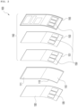
- FIG. 2 is an exploded perspective view showing the display module according to the embodiment of the present invention.
- the display module according to the embodiment of the present invention is configured such that devices are attached to the front surface and a rear surface of the display panel 110, wherein the polarization portion 130, described with reference to FIG. 1 , is attached to the front surface of the display panel 110, and a backlight unit 150 is attached to the rear surface of the display panel 110.
- the backlight unit 150 may include a light source, a diffuser panel 151, a light guide panel 153, and a back cover 155.
- the light source, the light guide panel 153, and the diffuser panel 151 may be received in the back cover 155, which may be formed so as to be open at a front surface thereof.
- the back cover 155 may be formed so as to have a size corresponding to the size of the display panel 110 such that the display panel 110 can also be received in the back cover, and a reflector panel configured to reflect light from the light source in a direction in which the display panel 110 is located may be installed at the back cover 155.
- the light source may be constituted as the result of a plurality of LEDs being mounted on a circuit board.
- the light source may be installed at the rear of the back cover 155 to provide light to the display panel 110 located at the front of the backlight unit 150, or may be installed around the back cover 155 to provide light to the display panel 110 through the light guide panel 153, a description of which will follow.
- the light guide panel 153 may change the path of light generated by the light source in the direction in which the display panel 110 is located.
- the light guide panel 153 may be formed so as to have a sheet shape, and may have a light guide pattern configured to change the path of light provided by the light source in the direction in which the display panel 110 is located.
- the diffuser panel 151 may diffuse light provided by the light source and may provide the diffused light to the display panel 110. To this end, the diffuser panel 151 diffuses light provided through the light guide panel 153 and provides the diffused light to the display panel 110.
- each of the diffuser panel 151, the light guide panel 153, and the back cover 155, which constitutes the backlight unit 150 includes a plurality of cutting areas (backlight transmission portions 159) such that the rear of the display panel 110 is visible, wherein the plurality of cutting areas is formed at the position corresponding to the polarization transmission portion 135 formed at the polarization portion 130.
- the light guide panel 153 may further include a predetermined member that reacts to light. That is, the predetermined member that reacts to light may be attached to each of inner surfaces of the plurality of cutting areas (backlight transmission portions 159) formed in the light guide panel 153. Examples in which the predetermined members are attached to the light guide panel 153 are illustrated in FIGs. 3 and 4 .
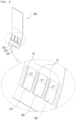
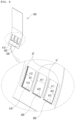
- FIGs. 3 and 4 are perspective views respectively showing light guide panels according to first and second embodiments of the present invention.
- the light guide panel 200 according to the first embodiment of the present invention includes three backlight transmission portions 210, 220, and 230 arranged in a line, and a predetermined member 211 that reacts to light is attached to each of inner surfaces thereof.
- the predetermined member 211 which is a reflector, may be implemented by a tape, a sheet, or a film, and may be attached to at least one of the inner surfaces of the three backlight transmission portions 210, 220, and 230.
- a coating solution having a color that reflects light may be applied to opposite surfaces of the predetermined member 211.
- a white coating solution may be applied to the opposite surfaces of the predetermined member 211.
- a white reflector 211 having a white coating solution applied to opposite surfaces thereof is attached to left/right inner surfaces of each of the three backlight transmission portions 210, 220, and 230, whereby it is possible to solve a problem in that brightness of the transmission area of each of the backlight transmission portions 210, 220, and 230 and brightness of the area a1 between the backlight transmission portions 210, 220, and 230 are lower than brightness of the other areas.
- an outside area a2 of each of the backlight transmission portions 210 and 230 adjacent to left/right light emission portions may be excessively brightened.
- no white reflector 211 may be attached to the inner surface, adjacent to the outside area a2, of each of the backlight transmission portions 210 and 230 adjacent to the left/right light emission portions, or a member having another property may be attached thereto.
- FIG. 4 is a view illustrating the second embodiment of the present invention, which solves the above problem.
- the light guide panel 300 according to the second embodiment of the present invention includes three backlight transmission portions 310, 320, and 330 arranged in a line, and first and second members 311 and 312 that react to light are optionally attached to each of inner surfaces thereof.
- the first and second members 311 and 312 are members having different properties in which the first and second members react to light, wherein the first member 311 has a property in which both surfaces of the first member reflect light and the second member 312 has a property in which one surface of the second member reflects light and the other surface of the second member offsets the reflected light.
- the first member 311 may be a first reflector having a coating solution having a color that reflects light (e.g. white) applied to opposite surfaces thereof
- the second member 312 may be a second reflector having a coating solution having a color that reflects light (e.g. white) applied to one surface thereof and a coating solution having a color that offsets light (e.g. gray) applied to the other surface thereof.
- each of the first member 311 and the second member 312 may be implemented by a gray tape, a gray sheet, or a gray film.
- the first member 311 reflects light.
- the second member 312 reflects light to the transmission area of each of the backlight transmission portions 310 and 330 and offsets light reflected to the outside area a2.
- the first member 311 may be attached to an inner surface of each of the backlight transmission portions 310, 320, and 330 adjacent to the area a1 between the backlight transmission portions 310, 320, and 330
- the second member 312 is attached to the inner surface of each of the backlight transmission portions 310 and 330 adjacent to the outside area a2.
- the second member 312 is attached such that one surface of the second member having a coating solution having a color that reflects light (e.g. white) applied thereto faces the transmission area of each of the backlight transmission portions 310 and 330 and the other surface of the second member having a coating solution having a color that offsets light (e.g. gray) applied thereto faces the outside area a2.
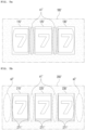
- FIGs. 5A to 5C are views illustrating use examples of display modules having the light guide panels according to the first and second embodiments of the present invention.
- An example in which the operation state of a reel game machine is displayed when the reel game machine is located at the rear of each of the display modules having the light guide panels according to the first and second embodiments of the present invention applied thereto will be described while comparing with a conventional case.
- FIG. 5A shows a use example of a display module 100' having a conventional light guide panel. Referring to FIG. 5A , it can be seen that, for the conventional display module 100' having three transmission portions 110', 120', and 130', an area a1' between the transmission portions 110', 120', and 130' is darker than other areas.
- FIG. 5B is a view showing a use example of a display module 200' having the light guide panel illustrated in FIG. 3 applied thereto.
- the predetermined member 211 is attached to at least one of the inner surfaces of the backlight transmission portions 210, 220, and 230 formed in the light guide panel 200, wherein the predetermined member 211 is attached to both the left/right inner surfaces of each of the backlight transmission portions 210, 220, and 230, as in the first embodiment of the present invention
- display areas 210', 220', and 230' configured to display the operation state of the reel game machine located at the rear of the display module 200' and areas a1' and a2' around the display areas 210', 220', and 230' are not darker than the other areas.
- the first embodiment of the present invention as described above, it is possible to solve a problem in that brightness of the screen around the cutting areas is reduced as the result of cutting a part of the light guide panel 200
- the left/right areas a2' of the display areas 210', 220', and 230' i.e. the left side of the display area 210' and the right side of the display area 230'
- the left/right areas a2' of the display areas 210', 220', and 230' are excessively brightened.
- FIG. 5C which is a view showing a use example of a display module capable of solving the problem in that the excessively brightened areas are generated, as described above, shows a use example of a display module 300' having the light guide panel illustrated in FIG. 4 applied thereto.
- the left side of the display area 310' and the right side of the display area 330') is similar to brightness of the other areas.
- the second embodiment of the present invention as claimed in claim 1, as described above it is possible to solve a problem that may occur when the first embodiment of the present invention is applied, i.e. a problem in that a specific area is excessively brightened.
- FIG. 6 is a perspective view showing a light guide panel according to a third embodiment of the present invention.
- the light guide panel 400 according to the third embodiment of the present invention includes three backlight transmission portions 410, 420, and 430 disposed in a line, and first to third members 411 to 413 having different properties in which the first to third members react to light are optionally attached to each of inner surfaces thereof.
- the first member 411 reflects light.
- the second member 412 reflects light to the transmission area of each of the backlight transmission portions 410 and 430 and offsets light reflected to the outside area a2.
- the third member 413 diffuses the light.
- the third member 413 may be implemented by a diffuser sheet configured to diffuse light.
- the attachment position of the third member 413 is not limited to the position illustrated in FIG. 6 . That is, the third member 413 is attached to an inner surface adjacent to the position at which the hot spot is generated.
- the third member 413 may be attached to the upper part of each of the backlight transmission portions 410, 420, and 430.
- the inner surface adjacent to the position at which the hot spot is generated may be etched, without attachment of a separate member, in order to remove the hot spot. In this case, it is possible to obtain the same effect.
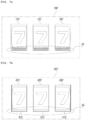
- FIGs. 7A and 7B are views illustrating use examples of a display module having the light guide panel according to the third embodiment of the present invention.
- An example in which the operation state of a reel game machine is displayed when the reel game machine is located at the rear of the display module having the light guide panel according to the third embodiment of the present invention applied thereto will be described while comparing with a conventional case.
- FIG. 7A shows a use example of a display module 100' having a conventional light guide panel having transmission portions.
- FIG. 7A shows an example in which, when light is incident from a light emission portion located under the conventional light guide panel, a hot spot is generated at a lower part a3 of each of transmission portions 110', 120', and 130' included in the display module 100'
- FIG. 7B which is a view showing a use example of the display module from which the hot spot has been removed, shows a use example of a display module 400' having the light guide panel illustrated in FIG. 6 applied thereto.
- FIGs. 6 and 7B it can be seen that, when the third member 413 is attached to the lower part of each of the inner surfaces of the backlight transmission portions 410, 420, and 430 or the lower part is etched, as in the third embodiment of the present invention shown in FIG. 6 , it is possible to remove the hot spot.
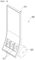
- FIG. 8 is a schematic perspective view showing a game machine having a display module having transmission portions according to an embodiment of the present invention.
- the game machine 500 according to the embodiment of the present invention includes a display module 510 having transmission portions and a real game unit 520 configured to execute a game.
- the real game unit 520 may be moved according to mechanical operation in order to execute the game.
- the real game unit 520 is a reel unit of a reel game machine is shown; however, the real game unit 520 may be implemented in various forms capable of executing the game.
- the reel unit 520 shown in the figure may be configured such that numbers or figures are printed on the circumference of each of a plurality of rotary reels, and the game may be executed in the manner in which the plurality of rotary reels that are being rotated is arbitrarily stopped and points are awarded based on the numbers or the figures seen from the front.
- the real game unit 520 may be may be located at the rear of the display module 510 including the plurality of transmission portions 511 such that, when a gamer looks at the display module 510, the real game unit is visible through the transmission portions 511. Consequently, the gamer may play the game using an image displayed on the display module 510 and the real game unit 520 seen through the transmission portions 511.
- the game machine 500 having the display module 510 having the transmission portions 511 according to the embodiment of the present invention may include a manipulation mechanism.
- a manipulation signal may be generated from the manipulation mechanism through direct manipulation of the gamer such that the game is executed.
- the manipulation mechanism may be implemented by a button or a joystick.
- the manipulation mechanism may also be implemented by a touch panel disposed so as to overlap the display module 510 having the transmission portions in order to generate a touch signal.
- the gamer may manipulate the manipulation mechanism to play the game while looking at the image displayed on the display module 510 and the real game unit 520 seen through the transmission portions 511.
- the game machine 500 it is possible to solve a problem in that brightness of the display areas of the transmission portions 511 and brightness of the areas around the transmission portions 511 are reduced, whereby it is possible for a user to focus on the game.
Landscapes
- Physics & Mathematics (AREA)
- General Physics & Mathematics (AREA)
- Nonlinear Science (AREA)
- Optics & Photonics (AREA)
- Chemical & Material Sciences (AREA)
- Crystallography & Structural Chemistry (AREA)
- Mathematical Physics (AREA)
- Engineering & Computer Science (AREA)
- Manufacturing & Machinery (AREA)
- Illuminated Signs And Luminous Advertising (AREA)
- Planar Illumination Modules (AREA)
- Liquid Crystal (AREA)
- Display Devices Of Pinball Game Machines (AREA)
- Pinball Game Machines (AREA)
Claims (5)
- Lichtleitertafel (153), die einen Durchlassabschnitt (135) aufweist, wobeidie Lichtleitertafel (153) mindestens einen Ausschnittbereich umfasst, der konfiguriert ist zum Implementieren des Durchlassabschnitts (135), undein vorbestimmtes Element (211), das konfiguriert ist zum Reagieren auf Licht, an mindestens einer Innenfläche des Ausschnittbereichs befestigt ist,wobei eine Vielzahl von Ausschnittbereichen in einer Reihe angeordnet sind, wobeiein erstes Element (311), das konfiguriert ist zum Verhindern einer Verringerung der Helligkeit des Lichts, an einer ersten Innenfläche von jedem der Ausschnittbereiche von den Innenflächen der Ausschnittbereiche befestigt ist, wobei sich die erste Innenfläche in der Nähe eines anderen Ausschnittbereichs befindet, unddas erste Element (311) aus einem beliebigen eines Bands, einer Folie und eines Films gebildet ist, die jeweils ein Material aufweisen, das eine Farbe aufweist, die konfiguriert ist, um Licht zu reflektieren, das auf entgegengesetzte Oberflächen davon angewandt wird; und wobeiein zweites Element (312), das konfiguriert ist zum Reagieren auf Licht, an einer zweiten Innenfläche von jedem der Ausschnittbereiche von den Innenflächen der Ausschnittbereiche befestigt ist, wobei sich die zweite Innenfläche nicht in der Nähe eines anderen Ausschnittbereichs befindet, unddas zweite Element (312) aus einem beliebigen eines Bands, einer Folie und eines Films gebildet ist, die jeweils ein Material, das eine Farbe aufweist, die konfiguriert ist, um Licht zu reflektieren, das auf eine Oberfläche davon angewandt wird, die dem Ausschnittbereich zugewandt ist, und ein Material aufweisen, das eine Farbe aufweist, die konfiguriert ist, um ein Licht zu versetzen, das auf die andere Oberfläche davon angewandt wird, sodass der äußere Bereich, welcher der Bereich ist, welcher der anderen Oberfläche zugewandt ist, im Vergleich zur Helligkeit zwischen den Ausschnittbereichen nicht übermäßig erhellt wird.
- Lichtleitertafel (153) nach Anspruch 1, wobei eine Diffusorplatte, die konfiguriert ist zum Entfernen eines Hotspots, der erzeugt wird, wenn Licht, das von einem Lichtemissionsabschnitt abgestrahlt wird, der außerhalb der Lichtleitertafel (153) bereitgestellt wird, durch die Innenfläche von jedem der Ausschnittbereiche übertragen wird, an mindestens einer Innenfläche der Ausschnittbereiche befestigt wird.
- Lichtleitertafel (153) nach Anspruch 1, wobei mindestens eine der Innenflächen der Ausschnittbereiche geätzt wird, um einen Hotspot zu entfernen, der erzeugt wird, wenn Licht, das von einem Lichtemissionsabschnitt abgestrahlt wird, der außerhalb der Lichtleitertafel (153) bereitgestellt wird, durch die Innenfläche von jedem der Ausschnittbereiche übertragen wird.
- Anzeigemodul (100), umfassend:eine Anzeigetafel (110), die konfiguriert ist, um ein Bild anzuzeigen;einen Polarisationsabschnitt (130), der an der Anzeigetafel (110) befestigt ist, wobei der Polarisationsabschnitt (130) konfiguriert ist, um optional Licht in Abhängigkeit von der Schwingungsrichtung desselben zu übertragen, wobei der Polarisationsabschnitt (130) mindestens einen ersten Ausschnittbereich umfasst, der so geschnitten ist, dass eine Rückseite der Anzeigetafel (110) durch den ersten Ausschnittbereich zu sehen ist; undeine Rückbeleuchtungseinheit (150), die konfiguriert ist, um die Anzeigetafel (110) mit Licht zu versorgen, wobei die Rückbeleuchtungseinheit (150) einen zweiten Ausschnittbereich umfasst, der so geschnitten ist, dass er dem ersten Ausschnittbereich entspricht, sodass die Rückseite der Anzeigetafel (110) durch den zweiten Ausschnittbereich zu sehen ist, wobeidie Rückbeleuchtungseinheit (150) eine Lichtleitertafel (153) nach einem der Ansprüche 1 bis 3 umfasst,wobei einer aus der Vielzahl von Ausschnittbereichen der Lichtleitertafel (153) einen dritten Ausschnittbereich bildet, der dem ersten und dem zweiten Ausschnittbereich entspricht.
- Spielautomat (500), umfassend:ein Anzeigemodul (100, 510) nach Anspruch 4 undeine Walzenspieleinheit (520), die sich auf der Rückseite des Anzeigemoduls (100) befindet, wobei die Walzenspieleinheit (520) konfiguriert ist zum Bereitstellen eines Walzenspiels durch den ersten Ausschnittbereich des Polarisationsabschnitts (130).
Applications Claiming Priority (2)
| Application Number | Priority Date | Filing Date | Title |
|---|---|---|---|
| KR1020200061925A KR102362710B1 (ko) | 2020-05-22 | 2020-05-22 | 투과부를 갖는 도광판 및 디스플레이 모듈과, 이를 구비한 게임기 |
| PCT/KR2021/005345 WO2021235720A1 (ko) | 2020-05-22 | 2021-04-28 | 투과부를 갖는 도광판 및 디스플레이 모듈과, 이를 구비한 게임기 |
Publications (3)
| Publication Number | Publication Date |
|---|---|
| EP4155606A1 EP4155606A1 (de) | 2023-03-29 |
| EP4155606A4 EP4155606A4 (de) | 2024-07-03 |
| EP4155606B1 true EP4155606B1 (de) | 2025-06-11 |
Family
ID=78707995
Family Applications (1)
| Application Number | Title | Priority Date | Filing Date |
|---|---|---|---|
| EP21807640.4A Active EP4155606B1 (de) | 2020-05-22 | 2021-04-28 | Lichtleiterplatte und anzeigemodul mit durchlässigem teil und spielmaschine damit |
Country Status (6)
| Country | Link |
|---|---|
| US (1) | US12085806B2 (de) |
| EP (1) | EP4155606B1 (de) |
| JP (1) | JP7486846B2 (de) |
| KR (1) | KR102362710B1 (de) |
| AU (1) | AU2021276850B2 (de) |
| WO (1) | WO2021235720A1 (de) |
Families Citing this family (3)
| Publication number | Priority date | Publication date | Assignee | Title |
|---|---|---|---|---|
| USD850537S1 (en) | 2017-09-05 | 2019-06-04 | Aristocrat Technologies Australia Pty Limited | Gaming machine |
| USD1023156S1 (en) * | 2019-08-29 | 2024-04-16 | Aristocrat Technologies Australia Pty Limited | Gaming machine with stepper reel and display screen with a transitional graphical user interface |
| US12272202B2 (en) * | 2021-08-31 | 2025-04-08 | Aristocrat Technologies, Inc. | Electronic gaming machines with notched screens |
Family Cites Families (15)
| Publication number | Priority date | Publication date | Assignee | Title |
|---|---|---|---|---|
| JP3639298B1 (ja) * | 2003-05-14 | 2005-04-20 | アルゼ株式会社 | 遊技機 |
| US7219893B2 (en) * | 2003-05-14 | 2007-05-22 | Aruze Corporation | Gaming machine |
| CN100440005C (zh) | 2003-07-30 | 2008-12-03 | 株式会社日立显示器 | 液晶显示装置 |
| JP5016186B2 (ja) * | 2003-07-30 | 2012-09-05 | 株式会社ジャパンディスプレイイースト | 液晶表示装置 |
| JP4627174B2 (ja) | 2003-12-02 | 2011-02-09 | サミー株式会社 | ドーナツ液晶を備えた遊技機 |
| JP2005056859A (ja) * | 2004-11-02 | 2005-03-03 | Enplas Corp | サイドライト型面光源装置及び導光板 |
| JP2007033908A (ja) * | 2005-07-27 | 2007-02-08 | Toshiba Matsushita Display Technology Co Ltd | 液晶表示装置 |
| JP4939893B2 (ja) * | 2006-10-13 | 2012-05-30 | 株式会社 日立ディスプレイズ | 液晶表示装置 |
| JP2010026022A (ja) * | 2008-07-16 | 2010-02-04 | Stanley Electric Co Ltd | 液晶表示装置 |
| KR101068154B1 (ko) * | 2009-10-27 | 2011-09-27 | (주)코텍 | 디스플레이장치 |
| KR101153892B1 (ko) * | 2010-07-06 | 2012-06-05 | (주)코텍 | 서브백라이트를 구비한 디스플레이장치 |
| WO2017061312A1 (ja) * | 2015-10-05 | 2017-04-13 | シャープ株式会社 | 照明装置及び表示装置 |
| KR101702589B1 (ko) * | 2015-11-30 | 2017-02-03 | 엘지디스플레이 주식회사 | 홀을 구비한 이형 디스플레이 |
| KR101970330B1 (ko) | 2018-04-10 | 2019-08-13 | 이피네트시스템즈 주식회사 | 곡면 디스플레이 패널의 제조 방법 |
| KR20200020241A (ko) * | 2018-08-16 | 2020-02-26 | 주식회사 토비스 | 투과부를 갖는 디스플레이 모듈 및 이를 구비한 게임기 |
-
2020
- 2020-05-22 KR KR1020200061925A patent/KR102362710B1/ko active Active
-
2021
- 2021-04-28 WO PCT/KR2021/005345 patent/WO2021235720A1/ko not_active Ceased
- 2021-04-28 JP JP2022571141A patent/JP7486846B2/ja active Active
- 2021-04-28 AU AU2021276850A patent/AU2021276850B2/en active Active
- 2021-04-28 EP EP21807640.4A patent/EP4155606B1/de active Active
- 2021-04-28 US US17/926,626 patent/US12085806B2/en active Active
Also Published As
| Publication number | Publication date |
|---|---|
| AU2021276850B2 (en) | 2026-05-07 |
| KR20210144480A (ko) | 2021-11-30 |
| JP2023526496A (ja) | 2023-06-21 |
| KR102362710B1 (ko) | 2022-02-14 |
| AU2021276850A1 (en) | 2023-01-05 |
| EP4155606A4 (de) | 2024-07-03 |
| JP7486846B2 (ja) | 2024-05-20 |
| EP4155606A1 (de) | 2023-03-29 |
| WO2021235720A1 (ko) | 2021-11-25 |
| US20230185130A1 (en) | 2023-06-15 |
| US12085806B2 (en) | 2024-09-10 |
Similar Documents
| Publication | Publication Date | Title |
|---|---|---|
| US12085806B2 (en) | Light guide plate and display module having transmissive part, and game machine having same | |
| KR20140138858A (ko) | 지향성 백라이팅을 이용한 디스플레이 장치 | |
| KR20140137373A (ko) | 조명식 로고 구조체를 갖춘 전자 디바이스 | |
| CN110955084B (zh) | 一种显示装置及其驱动方法 | |
| CN102588766B (zh) | 发光装置和图像显示设备 | |
| US8830421B2 (en) | Display device including sub-backlight | |
| JP5160635B2 (ja) | 液晶表示ユニット、液晶表示ユニットの制御方法及び遊技装置 | |
| JP2005148440A (ja) | 照明光制御シートとそれを用いた表示装置 | |
| US8355094B2 (en) | Liquid crystal display unit and gaming device | |
| US8836891B2 (en) | Liquid crystal display device and game device | |
| US8203659B2 (en) | LCD display and gaming machine combination | |
| WO2010095303A1 (ja) | 液晶表示装置および遊技装置 | |
| KR101165437B1 (ko) | 디스플레이장치 | |
| TWI745738B (zh) | 背光模組及顯示裝置 | |
| WO2013161945A1 (ja) | 光源装置及び電子機器 | |
| KR20200020241A (ko) | 투과부를 갖는 디스플레이 모듈 및 이를 구비한 게임기 | |
| WO2026091173A1 (zh) | 显示装置及电子设备 | |
| JP2005208372A (ja) | 液晶表示装置およびこれを用いた遊技機 | |
| KR200354621Y1 (ko) | 내부화면창을 구비한 액정표시장치 | |
| KR100587469B1 (ko) | 내부화면창을 구비한 액정표시장치 | |
| KR102068139B1 (ko) | 프리즘시트와 이를 포함하는 백라이트 유닛 및 디스플레이 장치 | |
| CN104076520A (zh) | 显示器 | |
| HK1078655B (en) | Backlighting device for an information display element of a portable object | |
| HK1078655A1 (zh) | 用於便携式物体的信息显示元件的背光装置 |
Legal Events
| Date | Code | Title | Description |
|---|---|---|---|
| STAA | Information on the status of an ep patent application or granted ep patent |
Free format text: STATUS: THE INTERNATIONAL PUBLICATION HAS BEEN MADE |
|
| PUAI | Public reference made under article 153(3) epc to a published international application that has entered the european phase |
Free format text: ORIGINAL CODE: 0009012 |
|
| STAA | Information on the status of an ep patent application or granted ep patent |
Free format text: STATUS: REQUEST FOR EXAMINATION WAS MADE |
|
| 17P | Request for examination filed |
Effective date: 20221220 |
|
| AK | Designated contracting states |
Kind code of ref document: A1 Designated state(s): AL AT BE BG CH CY CZ DE DK EE ES FI FR GB GR HR HU IE IS IT LI LT LU LV MC MK MT NL NO PL PT RO RS SE SI SK SM TR |
|
| DAV | Request for validation of the european patent (deleted) | ||
| DAX | Request for extension of the european patent (deleted) | ||
| REG | Reference to a national code |
Ref country code: DE Ref legal event code: R079 Free format text: PREVIOUS MAIN CLASS: F21V0008000000 Ipc: G02B0006000000 Ref document number: 602021032218 Country of ref document: DE |
|
| A4 | Supplementary search report drawn up and despatched |
Effective date: 20240603 |
|
| RIC1 | Information provided on ipc code assigned before grant |
Ipc: F21V 8/00 20060101ALN20240527BHEP Ipc: G07F 17/32 20060101ALI20240527BHEP Ipc: G02F 1/13357 20060101ALI20240527BHEP Ipc: G02B 6/00 20060101AFI20240527BHEP |
|
| GRAP | Despatch of communication of intention to grant a patent |
Free format text: ORIGINAL CODE: EPIDOSNIGR1 |
|
| STAA | Information on the status of an ep patent application or granted ep patent |
Free format text: STATUS: GRANT OF PATENT IS INTENDED |
|
| RIC1 | Information provided on ipc code assigned before grant |
Ipc: F21V 8/00 20060101ALN20250205BHEP Ipc: G07F 17/32 20060101ALI20250205BHEP Ipc: G02F 1/13357 20060101ALI20250205BHEP Ipc: G02B 6/00 20060101AFI20250205BHEP |
|
| INTG | Intention to grant announced |
Effective date: 20250217 |
|
| GRAS | Grant fee paid |
Free format text: ORIGINAL CODE: EPIDOSNIGR3 |
|
| GRAA | (expected) grant |
Free format text: ORIGINAL CODE: 0009210 |
|
| STAA | Information on the status of an ep patent application or granted ep patent |
Free format text: STATUS: THE PATENT HAS BEEN GRANTED |
|
| AK | Designated contracting states |
Kind code of ref document: B1 Designated state(s): AL AT BE BG CH CY CZ DE DK EE ES FI FR GB GR HR HU IE IS IT LI LT LU LV MC MK MT NL NO PL PT RO RS SE SI SK SM TR |
|
| REG | Reference to a national code |
Ref country code: GB Ref legal event code: FG4D |
|
| REG | Reference to a national code |
Ref country code: CH Ref legal event code: EP |
|
| REG | Reference to a national code |
Ref country code: DE Ref legal event code: R096 Ref document number: 602021032218 Country of ref document: DE |
|
| REG | Reference to a national code |
Ref country code: IE Ref legal event code: FG4D |
|
| PG25 | Lapsed in a contracting state [announced via postgrant information from national office to epo] |
Ref country code: ES Free format text: LAPSE BECAUSE OF FAILURE TO SUBMIT A TRANSLATION OF THE DESCRIPTION OR TO PAY THE FEE WITHIN THE PRESCRIBED TIME-LIMIT Effective date: 20250611 Ref country code: FI Free format text: LAPSE BECAUSE OF FAILURE TO SUBMIT A TRANSLATION OF THE DESCRIPTION OR TO PAY THE FEE WITHIN THE PRESCRIBED TIME-LIMIT Effective date: 20250611 |
|
| REG | Reference to a national code |
Ref country code: LT Ref legal event code: MG9D |
|
| PG25 | Lapsed in a contracting state [announced via postgrant information from national office to epo] |
Ref country code: GR Free format text: LAPSE BECAUSE OF FAILURE TO SUBMIT A TRANSLATION OF THE DESCRIPTION OR TO PAY THE FEE WITHIN THE PRESCRIBED TIME-LIMIT Effective date: 20250912 Ref country code: NO Free format text: LAPSE BECAUSE OF FAILURE TO SUBMIT A TRANSLATION OF THE DESCRIPTION OR TO PAY THE FEE WITHIN THE PRESCRIBED TIME-LIMIT Effective date: 20250911 |
|
| REG | Reference to a national code |
Ref country code: NL Ref legal event code: MP Effective date: 20250611 |
|
| PG25 | Lapsed in a contracting state [announced via postgrant information from national office to epo] |
Ref country code: BG Free format text: LAPSE BECAUSE OF FAILURE TO SUBMIT A TRANSLATION OF THE DESCRIPTION OR TO PAY THE FEE WITHIN THE PRESCRIBED TIME-LIMIT Effective date: 20250611 |
|
| PG25 | Lapsed in a contracting state [announced via postgrant information from national office to epo] |
Ref country code: HR Free format text: LAPSE BECAUSE OF FAILURE TO SUBMIT A TRANSLATION OF THE DESCRIPTION OR TO PAY THE FEE WITHIN THE PRESCRIBED TIME-LIMIT Effective date: 20250611 |
|
| PG25 | Lapsed in a contracting state [announced via postgrant information from national office to epo] |
Ref country code: RS Free format text: LAPSE BECAUSE OF FAILURE TO SUBMIT A TRANSLATION OF THE DESCRIPTION OR TO PAY THE FEE WITHIN THE PRESCRIBED TIME-LIMIT Effective date: 20250911 |
|
| PG25 | Lapsed in a contracting state [announced via postgrant information from national office to epo] |
Ref country code: LV Free format text: LAPSE BECAUSE OF FAILURE TO SUBMIT A TRANSLATION OF THE DESCRIPTION OR TO PAY THE FEE WITHIN THE PRESCRIBED TIME-LIMIT Effective date: 20250611 |
|
| PG25 | Lapsed in a contracting state [announced via postgrant information from national office to epo] |
Ref country code: NL Free format text: LAPSE BECAUSE OF FAILURE TO SUBMIT A TRANSLATION OF THE DESCRIPTION OR TO PAY THE FEE WITHIN THE PRESCRIBED TIME-LIMIT Effective date: 20250611 |
|
| PG25 | Lapsed in a contracting state [announced via postgrant information from national office to epo] |
Ref country code: PT Free format text: LAPSE BECAUSE OF FAILURE TO SUBMIT A TRANSLATION OF THE DESCRIPTION OR TO PAY THE FEE WITHIN THE PRESCRIBED TIME-LIMIT Effective date: 20251013 |
|
| PG25 | Lapsed in a contracting state [announced via postgrant information from national office to epo] |
Ref country code: IS Free format text: LAPSE BECAUSE OF FAILURE TO SUBMIT A TRANSLATION OF THE DESCRIPTION OR TO PAY THE FEE WITHIN THE PRESCRIBED TIME-LIMIT Effective date: 20251011 |
|
| PG25 | Lapsed in a contracting state [announced via postgrant information from national office to epo] |
Ref country code: SM Free format text: LAPSE BECAUSE OF FAILURE TO SUBMIT A TRANSLATION OF THE DESCRIPTION OR TO PAY THE FEE WITHIN THE PRESCRIBED TIME-LIMIT Effective date: 20250611 |
|
| PG25 | Lapsed in a contracting state [announced via postgrant information from national office to epo] |
Ref country code: CZ Free format text: LAPSE BECAUSE OF FAILURE TO SUBMIT A TRANSLATION OF THE DESCRIPTION OR TO PAY THE FEE WITHIN THE PRESCRIBED TIME-LIMIT Effective date: 20250611 |
|
| PG25 | Lapsed in a contracting state [announced via postgrant information from national office to epo] |
Ref country code: PL Free format text: LAPSE BECAUSE OF FAILURE TO SUBMIT A TRANSLATION OF THE DESCRIPTION OR TO PAY THE FEE WITHIN THE PRESCRIBED TIME-LIMIT Effective date: 20250611 |
|
| PG25 | Lapsed in a contracting state [announced via postgrant information from national office to epo] |
Ref country code: EE Free format text: LAPSE BECAUSE OF FAILURE TO SUBMIT A TRANSLATION OF THE DESCRIPTION OR TO PAY THE FEE WITHIN THE PRESCRIBED TIME-LIMIT Effective date: 20250611 |
|
| PG25 | Lapsed in a contracting state [announced via postgrant information from national office to epo] |
Ref country code: SK Free format text: LAPSE BECAUSE OF FAILURE TO SUBMIT A TRANSLATION OF THE DESCRIPTION OR TO PAY THE FEE WITHIN THE PRESCRIBED TIME-LIMIT Effective date: 20250611 |
|
| REG | Reference to a national code |
Ref country code: DE Ref legal event code: R097 Ref document number: 602021032218 Country of ref document: DE |
|
| PGFP | Annual fee paid to national office [announced via postgrant information from national office to epo] |
Ref country code: GB Payment date: 20260310 Year of fee payment: 6 |
|
| PG25 | Lapsed in a contracting state [announced via postgrant information from national office to epo] |
Ref country code: DK Free format text: LAPSE BECAUSE OF FAILURE TO SUBMIT A TRANSLATION OF THE DESCRIPTION OR TO PAY THE FEE WITHIN THE PRESCRIBED TIME-LIMIT Effective date: 20250611 |
|
| PG25 | Lapsed in a contracting state [announced via postgrant information from national office to epo] |
Ref country code: IT Free format text: LAPSE BECAUSE OF FAILURE TO SUBMIT A TRANSLATION OF THE DESCRIPTION OR TO PAY THE FEE WITHIN THE PRESCRIBED TIME-LIMIT Effective date: 20250611 |
|
| PLBE | No opposition filed within time limit |
Free format text: ORIGINAL CODE: 0009261 |
|
| STAA | Information on the status of an ep patent application or granted ep patent |
Free format text: STATUS: NO OPPOSITION FILED WITHIN TIME LIMIT |
|
| REG | Reference to a national code |
Ref country code: CH Ref legal event code: L10 Free format text: ST27 STATUS EVENT CODE: U-0-0-L10-L00 (AS PROVIDED BY THE NATIONAL OFFICE) Effective date: 20260423 |
|
| 26N | No opposition filed |
Effective date: 20260312 |
|
| PG25 | Lapsed in a contracting state [announced via postgrant information from national office to epo] |
Ref country code: LT Free format text: LAPSE BECAUSE OF FAILURE TO SUBMIT A TRANSLATION OF THE DESCRIPTION OR TO PAY THE FEE WITHIN THE PRESCRIBED TIME-LIMIT Effective date: 20250611 |
|
| PGFP | Annual fee paid to national office [announced via postgrant information from national office to epo] |
Ref country code: DE Payment date: 20260305 Year of fee payment: 6 |
|
| PGFP | Annual fee paid to national office [announced via postgrant information from national office to epo] |
Ref country code: AT Payment date: 20260325 Year of fee payment: 6 |
|
| REG | Reference to a national code |
Ref country code: AT Ref legal event code: UEP Ref document number: 1802699 Country of ref document: AT Kind code of ref document: T Effective date: 20250611 |
|
| PG25 | Lapsed in a contracting state [announced via postgrant information from national office to epo] |
Ref country code: SE Free format text: LAPSE BECAUSE OF FAILURE TO SUBMIT A TRANSLATION OF THE DESCRIPTION OR TO PAY THE FEE WITHIN THE PRESCRIBED TIME-LIMIT Effective date: 20250611 |