EP4155643A1 - Dispositif et procédé de séchage de matériau, ainsi qu'installation de mélange d'asphalte doté d'un tel dispositif - Google Patents
Dispositif et procédé de séchage de matériau, ainsi qu'installation de mélange d'asphalte doté d'un tel dispositif Download PDFInfo
- Publication number
- EP4155643A1 EP4155643A1 EP22190889.0A EP22190889A EP4155643A1 EP 4155643 A1 EP4155643 A1 EP 4155643A1 EP 22190889 A EP22190889 A EP 22190889A EP 4155643 A1 EP4155643 A1 EP 4155643A1
- Authority
- EP
- European Patent Office
- Prior art keywords
- burner
- rotary kiln
- air
- hydrogen gas
- flame
- Prior art date
- Legal status (The legal status is an assumption and is not a legal conclusion. Google has not performed a legal analysis and makes no representation as to the accuracy of the status listed.)
- Pending
Links
Images


Classifications
-
- F—MECHANICAL ENGINEERING; LIGHTING; HEATING; WEAPONS; BLASTING
- F26—DRYING
- F26B—DRYING SOLID MATERIALS OR OBJECTS BY REMOVING LIQUID THEREFROM
- F26B11/00—Machines or apparatus for drying solid materials or objects with movement which is non-progressive
- F26B11/02—Machines or apparatus for drying solid materials or objects with movement which is non-progressive in moving drums or other mainly-closed receptacles
- F26B11/028—Arrangements for the supply or exhaust of gaseous drying medium for direct heat transfer, e.g. perforated tubes, annular passages, burner arrangements, dust separation, combined direct and indirect heating
-
- F—MECHANICAL ENGINEERING; LIGHTING; HEATING; WEAPONS; BLASTING
- F27—FURNACES; KILNS; OVENS; RETORTS
- F27B—FURNACES, KILNS, OVENS OR RETORTS IN GENERAL; OPEN SINTERING OR LIKE APPARATUS
- F27B7/00—Rotary-drum furnaces, i.e. horizontal or slightly inclined
- F27B7/10—Rotary-drum furnaces, i.e. horizontal or slightly inclined internally heated, e.g. by means of passages in the wall
-
- E—FIXED CONSTRUCTIONS
- E01—CONSTRUCTION OF ROADS, RAILWAYS, OR BRIDGES
- E01C—CONSTRUCTION OF, OR SURFACES FOR, ROADS, SPORTS GROUNDS, OR THE LIKE; MACHINES OR AUXILIARY TOOLS FOR CONSTRUCTION OR REPAIR
- E01C19/00—Machines, tools or auxiliary devices for preparing or distributing paving materials, for working the placed materials, or for forming, consolidating, or finishing the paving
- E01C19/02—Machines, tools or auxiliary devices for preparing or distributing paving materials, for working the placed materials, or for forming, consolidating, or finishing the paving for preparing the materials
- E01C19/05—Crushing, pulverising or disintegrating apparatus; Aggregate screening, cleaning, drying or heating apparatus; Dust-collecting arrangements specially adapted therefor
-
- F—MECHANICAL ENGINEERING; LIGHTING; HEATING; WEAPONS; BLASTING
- F23—COMBUSTION APPARATUS; COMBUSTION PROCESSES
- F23C—METHODS OR APPARATUS FOR COMBUSTION USING FLUID FUEL OR SOLID FUEL SUSPENDED IN A CARRIER GAS OR AIR
- F23C1/00—Combustion apparatus specially adapted for combustion of two or more kinds of fuel simultaneously or alternately, at least one kind of fuel being either a fluid fuel or a solid fuel suspended in a carrier gas or air
- F23C1/08—Combustion apparatus specially adapted for combustion of two or more kinds of fuel simultaneously or alternately, at least one kind of fuel being either a fluid fuel or a solid fuel suspended in a carrier gas or air liquid and gaseous fuel
-
- F—MECHANICAL ENGINEERING; LIGHTING; HEATING; WEAPONS; BLASTING
- F23—COMBUSTION APPARATUS; COMBUSTION PROCESSES
- F23D—BURNERS
- F23D11/00—Burners using a direct spraying action of liquid droplets or vaporised liquid into the combustion space
- F23D11/001—Spraying nozzle combined with forced draft fan in one unit
-
- F—MECHANICAL ENGINEERING; LIGHTING; HEATING; WEAPONS; BLASTING
- F23—COMBUSTION APPARATUS; COMBUSTION PROCESSES
- F23D—BURNERS
- F23D14/00—Burners for combustion of a gas, e.g. of a gas stored under pressure as a liquid
- F23D14/02—Premix gas burners, i.e. in which gaseous fuel is mixed with combustion air upstream of the combustion zone
-
- F—MECHANICAL ENGINEERING; LIGHTING; HEATING; WEAPONS; BLASTING
- F23—COMBUSTION APPARATUS; COMBUSTION PROCESSES
- F23D—BURNERS
- F23D14/00—Burners for combustion of a gas, e.g. of a gas stored under pressure as a liquid
- F23D14/20—Non-premix gas burners, i.e. in which gaseous fuel is mixed with combustion air on arrival at the combustion zone
- F23D14/22—Non-premix gas burners, i.e. in which gaseous fuel is mixed with combustion air on arrival at the combustion zone with separate air and gas feed ducts, e.g. with ducts running parallel or crossing each other
- F23D14/24—Non-premix gas burners, i.e. in which gaseous fuel is mixed with combustion air on arrival at the combustion zone with separate air and gas feed ducts, e.g. with ducts running parallel or crossing each other at least one of the fluids being submitted to a swirling motion
-
- F—MECHANICAL ENGINEERING; LIGHTING; HEATING; WEAPONS; BLASTING
- F26—DRYING
- F26B—DRYING SOLID MATERIALS OR OBJECTS BY REMOVING LIQUID THEREFROM
- F26B11/00—Machines or apparatus for drying solid materials or objects with movement which is non-progressive
- F26B11/02—Machines or apparatus for drying solid materials or objects with movement which is non-progressive in moving drums or other mainly-closed receptacles
- F26B11/04—Machines or apparatus for drying solid materials or objects with movement which is non-progressive in moving drums or other mainly-closed receptacles rotating about a horizontal or slightly-inclined axis
- F26B11/0404—Machines or apparatus for drying solid materials or objects with movement which is non-progressive in moving drums or other mainly-closed receptacles rotating about a horizontal or slightly-inclined axis with internal subdivision of the drum, e.g. for subdividing or recycling the material to be dried
- F26B11/0418—Machines or apparatus for drying solid materials or objects with movement which is non-progressive in moving drums or other mainly-closed receptacles rotating about a horizontal or slightly-inclined axis with internal subdivision of the drum, e.g. for subdividing or recycling the material to be dried the subdivision consisting of a plurality of parallel tubes, e.g. through which the material to be dried is conveyed in single or multi-pass fashion
- F26B11/0427—Constructional details, e.g. arrangements of drives, supports, bearings, gas-sealing, heating medium supply or exhaust
-
- F—MECHANICAL ENGINEERING; LIGHTING; HEATING; WEAPONS; BLASTING
- F26—DRYING
- F26B—DRYING SOLID MATERIALS OR OBJECTS BY REMOVING LIQUID THEREFROM
- F26B11/00—Machines or apparatus for drying solid materials or objects with movement which is non-progressive
- F26B11/02—Machines or apparatus for drying solid materials or objects with movement which is non-progressive in moving drums or other mainly-closed receptacles
- F26B11/04—Machines or apparatus for drying solid materials or objects with movement which is non-progressive in moving drums or other mainly-closed receptacles rotating about a horizontal or slightly-inclined axis
- F26B11/0463—Machines or apparatus for drying solid materials or objects with movement which is non-progressive in moving drums or other mainly-closed receptacles rotating about a horizontal or slightly-inclined axis having internal elements, e.g. which are being moved or rotated by means other than the rotating drum wall
- F26B11/0477—Machines or apparatus for drying solid materials or objects with movement which is non-progressive in moving drums or other mainly-closed receptacles rotating about a horizontal or slightly-inclined axis having internal elements, e.g. which are being moved or rotated by means other than the rotating drum wall for mixing, stirring or conveying the materials to be dried, e.g. mounted to the wall, rotating with the drum
-
- F—MECHANICAL ENGINEERING; LIGHTING; HEATING; WEAPONS; BLASTING
- F26—DRYING
- F26B—DRYING SOLID MATERIALS OR OBJECTS BY REMOVING LIQUID THEREFROM
- F26B23/00—Heating arrangements
- F26B23/02—Heating arrangements using combustion heating
-
- F—MECHANICAL ENGINEERING; LIGHTING; HEATING; WEAPONS; BLASTING
- F26—DRYING
- F26B—DRYING SOLID MATERIALS OR OBJECTS BY REMOVING LIQUID THEREFROM
- F26B23/00—Heating arrangements
- F26B23/02—Heating arrangements using combustion heating
- F26B23/022—Heating arrangements using combustion heating incinerating volatiles in the dryer exhaust gases, the produced hot gases being wholly, partly or not recycled into the drying enclosure
-
- F—MECHANICAL ENGINEERING; LIGHTING; HEATING; WEAPONS; BLASTING
- F27—FURNACES; KILNS; OVENS; RETORTS
- F27B—FURNACES, KILNS, OVENS OR RETORTS IN GENERAL; OPEN SINTERING OR LIKE APPARATUS
- F27B7/00—Rotary-drum furnaces, i.e. horizontal or slightly inclined
- F27B7/14—Rotary-drum furnaces, i.e. horizontal or slightly inclined with means for agitating or moving the charge
- F27B7/16—Rotary-drum furnaces, i.e. horizontal or slightly inclined with means for agitating or moving the charge the means being fixed relatively to the drum, e.g. composite means
- F27B7/161—Rotary-drum furnaces, i.e. horizontal or slightly inclined with means for agitating or moving the charge the means being fixed relatively to the drum, e.g. composite means the means comprising projections jutting out from the wall
- F27B7/162—Rotary-drum furnaces, i.e. horizontal or slightly inclined with means for agitating or moving the charge the means being fixed relatively to the drum, e.g. composite means the means comprising projections jutting out from the wall the projections consisting of separate lifting elements, e.g. lifting shovels
-
- F—MECHANICAL ENGINEERING; LIGHTING; HEATING; WEAPONS; BLASTING
- F27—FURNACES; KILNS; OVENS; RETORTS
- F27B—FURNACES, KILNS, OVENS OR RETORTS IN GENERAL; OPEN SINTERING OR LIKE APPARATUS
- F27B7/00—Rotary-drum furnaces, i.e. horizontal or slightly inclined
- F27B7/14—Rotary-drum furnaces, i.e. horizontal or slightly inclined with means for agitating or moving the charge
- F27B7/18—Rotary-drum furnaces, i.e. horizontal or slightly inclined with means for agitating or moving the charge the means being movable within the drum
-
- F—MECHANICAL ENGINEERING; LIGHTING; HEATING; WEAPONS; BLASTING
- F23—COMBUSTION APPARATUS; COMBUSTION PROCESSES
- F23C—METHODS OR APPARATUS FOR COMBUSTION USING FLUID FUEL OR SOLID FUEL SUSPENDED IN A CARRIER GAS OR AIR
- F23C2201/00—Staged combustion
- F23C2201/30—Staged fuel supply
- F23C2201/301—Staged fuel supply with different fuels in stages
-
- F—MECHANICAL ENGINEERING; LIGHTING; HEATING; WEAPONS; BLASTING
- F23—COMBUSTION APPARATUS; COMBUSTION PROCESSES
- F23C—METHODS OR APPARATUS FOR COMBUSTION USING FLUID FUEL OR SOLID FUEL SUSPENDED IN A CARRIER GAS OR AIR
- F23C2900/00—Special features of, or arrangements for combustion apparatus using fluid fuels or solid fuels suspended in air; Combustion processes therefor
- F23C2900/9901—Combustion process using hydrogen, hydrogen peroxide water or brown gas as fuel
-
- F—MECHANICAL ENGINEERING; LIGHTING; HEATING; WEAPONS; BLASTING
- F23—COMBUSTION APPARATUS; COMBUSTION PROCESSES
- F23D—BURNERS
- F23D2900/00—Special features of, or arrangements for burners using fluid fuels or solid fuels suspended in a carrier gas
- F23D2900/14—Special features of gas burners
- F23D2900/14241—Post-mixing with swirling means
-
- F—MECHANICAL ENGINEERING; LIGHTING; HEATING; WEAPONS; BLASTING
- F23—COMBUSTION APPARATUS; COMBUSTION PROCESSES
- F23D—BURNERS
- F23D2900/00—Special features of, or arrangements for burners using fluid fuels or solid fuels suspended in a carrier gas
- F23D2900/14—Special features of gas burners
- F23D2900/14701—Swirling means inside the mixing tube or chamber to improve premixing
-
- F—MECHANICAL ENGINEERING; LIGHTING; HEATING; WEAPONS; BLASTING
- F23—COMBUSTION APPARATUS; COMBUSTION PROCESSES
- F23N—REGULATING OR CONTROLLING COMBUSTION
- F23N2237/00—Controlling
- F23N2237/08—Controlling two or more different types of fuel simultaneously
Definitions
- the invention relates to a device and a method for drying material and an asphalt mixing plant with such a device.
- the hydrogen gas burner is a burner in which hydrogen gas is burned to generate heat.
- the device can also include a number of burners which, in particular, are of identical design.
- the burners can also be designed differently, with at least one burner, in particular several burners and in particular all burners being designed as hydrogen gas burners. So hydrogen gas is used as fuel.
- the heat is generated at least in part and in particular exclusively by the combustion of hydrogen gas.
- the combustion of hydrogen gas is carbon dioxide-free, i. H. no carbon dioxide is produced. Combustion of hydrogen gas is climate friendly. Exhaust gases and emissions are reduced. It is particularly advantageous if the hydrogen gas has been generated from renewable energies, i.e. it is so-called green hydrogen.
- materials that can be used for an asphalt mixture such as used asphalt material, which is also referred to as recycling material or RC material, and/or mineral rock, in particular white mineral, are dried in the rotary kiln.
- the rotary kiln is designed to be rotatable about an axis of rotation and in particular has a cylindrical shape.
- the rotary kiln has a Material inlet at which the material to be dried is fed to the rotary kiln, and a material outlet at which the dried material is removed from the rotary kiln.
- the material inlet and the material outlet are arranged at a distance from one another in relation to the axis of rotation.
- the material inlet and the material outlet are each arranged in the region of the end faces of the rotary kiln and in particular are embodied on the opposite end face of the rotary kiln.
- the material inlet can have a material chute, a conveyor belt, a throw-in belt or other conveying techniques.
- the material outlet can have a material chute and/or a round elevator or other conveying technology.
- the rotary kiln In order to promote material transport in the rotary kiln, the rotary kiln is arranged with its axis of rotation inclined relative to a horizontal direction, in particular towards the material outlet.
- the angle of inclination is in particular at most 8°, in particular at most 5°, in particular at most 4°, in particular at most 3° and in particular at least 1°.
- the dwell time of the material inside the rotary kiln is in particular at least one minute and in particular at most 10 minutes.
- the burner that burns the hydrogen gas to generate heat is part of a heating unit that is coupled to the rotary kiln for heat transfer.
- coupled means that the burner and rotary kiln are coupled in terms of process technology.
- a burner flame generated by the burner can burn directly in the rotary kiln.
- the burner and rotary kiln are also physically coupled.
- the burner is located directly on the rotary kiln.
- the burner flame can also burn in a hot gas generator, which conducts the heat to the rotary kiln via a stream of air.
- the heat generated by the burner is fed into the rotary kiln by the heating unit.
- the supply of heat to the rotary kiln includes the generation of heat by the burner flame directly in the rotary kiln.
- the burner has a burner housing having a longitudinal axis with an air duct.
- air line describes the supply of combustion air.
- this can be done by a blower arranged in the burner housing, a blower connected via an air duct, or some other air supply.
- a flange is arranged on the burner housing, in particular on the front side, with which a muffler can be connected to the burner housing.
- Air in particular ambient air, is fed into the burner housing by means of the air line.
- the air line is connected to the burner housing axially with respect to the longitudinal axis. This simplifies the supply of air into the burner housing.
- a hydrogen gas line is connected to the burner, in particular to the burner housing, in order to supply hydrogen gas to the burner.
- a hydrogen gas nozzle is connected to the hydrogen gas line to selectively discharge the hydrogen gas in the torch body.
- a hydrogen gas nozzle can be designed as an annular nozzle, annular gap, gas lance, needle nozzle or as an outlet in any other form. This results in the generation of an air-hydrogen gas mixture and/or promoting the creation of a burner flame.
- the hydrogen gas nozzle is arranged in particular within the burner housing and is in particular designed as an annular nozzle with radial openings. There can also be several hydrogen gas nozzles that are designed identically or differently from one another.
- the hydrogen gas nozzles can be arranged at different positions with respect to the longitudinal axis, in particular in the radial, tangential and/or axial direction relative to one another.
- the burner additionally has a turbulence element which serves to swirl the combustion air, to mix fuel and combustion air, as a flame holder, as a holder for fuel nozzles, for pilot burners or other burner components and/or for similar purposes.
- a turbulence element is introduced in the variant carried out in order to turbulence the air in the burner housing relative to the longitudinal axis, in particular tangentially, radially and/or axially. This improves the mixing of the air with the hydrogen gas, in particular the homogeneity of the air-hydrogen gas mixture.
- the hydrogen gas nozzle is arranged adjacent to the swirling element and in particular opens directly upstream of the swirling element.
- the turbulator serves to define the shape of the burner flame generated by the burner.
- the flame should not exceed a maximum length along the axis of rotation of the rotary kiln, especially when it is arranged inside the rotary kiln, in order to prevent direct contact of the flame with the material in the rotary kiln.
- the maximum diameter of the flame should not exceed an upper limit value, ie the flame must not be too wide in order to subject the rotary kiln to excessive heat stress. The drying drum is protected.
- the burner housing has a burner head that is used to generate the burner flame.
- the burner head is to be understood as an opening which is arranged on the end face of the burner housing and at which the flame forms.
- the burner head can be designed to widen conically at least in sections along the longitudinal axis.
- a hydrogen reservoir can be provided in which hydrogen, in particular hydrogen gas, is stored.
- the hydrogen reservoir is connected to the burner housing in particular by means of the hydrogen gas line.
- a gas safety and/or gas control line is provided along the hydrogen gas line in order to ensure a reliable and safe supply of the hydrogen gas from the hydrogen reservoir into the burner housing.
- the gas safety and/or gas control line includes a shut-off valve, a gas filter, a gas pressure regulator, in particular with impulse lines, a pressure relief valve, in particular at least one pressure switch, in particular at least one safety shut-off valve, in particular further pressure switches, a gas control flap and/or an additional shut-off flap , and in particular at least one manometer.
- the hydrogen reservoir and/or the hydrogen gas line and in particular the hydrogen gas nozzle are in particular each made of a material that is suitable for storing, conveying and/or delivering hydrogen gas and in particular is approved for this.
- the components of the gas train are approved for use with hydrogen in particular.
- a turbulence element according to claim 2 ensures efficient air turbulence.
- a flow guide element is arranged in the burner housing in particular concentrically to the longitudinal axis.
- the flow guide element is stationary, ie immovable, arranged in the burner housing.
- the flow guide element has no moving parts.
- the flow guide element requires little maintenance and, in particular, is maintenance-free.
- the flow directing element is robust and reliable.
- the stationary flow guide element it is possible to feed the air line tangentially and/or radially with respect to the longitudinal axis of the burner housing, ie to connect the air line tangentially and/or radially to the burner housing.
- the turbulence element is thus formed by a tangential air supply.
- a baffle plate according to claim 3 enables an advantageous turbulence of the air and an advantageous generation of the air-hydrogen gas mixture.
- a plurality of blades arranged in a circle and oriented at an angle with respect to the longitudinal axis enable a targeted deflection of the axial air flow radially and/or tangentially outwards in the direction of the inner wall of the burner housing.
- the baffle plate has a section where the hydrogen gas nozzle opens out and a further area to which the air is supplied.
- the area for supplying the hydrogen gas is ring-shaped and oriented concentrically to the longitudinal axis.
- the area for supplying the air to the catchment disk is in particular arranged centrally, that is to say centrally.
- the two areas of the hydrogen gas and air supply on the baffle plate are designed separately from one another.
- at least one further area for the feed can be attached to the catchment disk a secondary fuel may be provided.
- This at least one additional area can be separate from or connected to the other areas. This additional area can be arranged centrically or eccentrically on the catchment disk.
- the turbulence element in particular in the form of the baffle plate, makes it easier to set the shape of the burner flame, regardless of the fuel used, in particular regardless of whether the secondary fuel is used in addition to the hydrogen gas.
- the shape of the burner flame is influenced in particular by the number, design and arrangement of the nozzles for supplying the hydrogen gas and the at least one secondary fuel.
- the shape of the flame also depends in particular on the air curve.
- the arrangement and/or the size of the different areas of the baffle plate essentially depends on the fuels to be burned. It is additionally or alternatively possible to change the geometry of the blades, to change the arrangement of the blades in the catchment disk and/or to provide additional guide elements, such as cones and/or attachment plates.
- a cooling cone according to claim 4 enables air staging within the burner housing.
- air staging air around the burner flame several combustion zones are created around them, which have different oxygen concentrations and in particular increase from the inside to the outside, i.e. in the radial direction. This increases the combustion area and thus also the dwell time of the components in the burner flame.
- thermal nitrogen oxides (NO x ) can be reduced by means of air staging and, in particular, complete combustion of the fuel, in particular hydrogen gas, can be achieved.
- the cooling cone has an expanding cone section.
- the cooling cone is arranged in the burner housing at the transition to the burner head.
- An annular gap is created between the outside of the cooling cone and the inside of the burner housing, in particular with a gap width that remains constant along the longitudinal axis.
- the cooling cone ensures air flow through the said annular gap, whereby the axially flowing air is kept away from the burner flame, i.e. guided around the burner flame and fed to the flame in the region of the burner head.
- This secondary air which has been guided around the burner flame, cools the burner head, particularly in the area of the cooling cone.
- the flame temperature can also be reduced in this way in order to reduce the formation of nitrogen oxides.
- air grading can also be ensured by means of an additional air connection, for example a secondary air connection.
- Secondary air can also be ambient air.
- a secondary air line can be a recirculation line in order to recirculate air contaminated with emissions from the rotary kiln and to post-combust and co-combust.
- measures to reduce nitrogen oxides are possible, in particular local combustion with different air ratios ( ⁇ ), which defines the mass ratio of air and fuel in the combustion chamber.
- ⁇ air ratios
- burns are possible at ⁇ >> 1 or at ⁇ ⁇ 1.
- a secondary fuel line according to claim 5 increases the variability of use of the burner.
- Several secondary fuel lines can also be connected to the burner, in order in particular to supply different types of secondary fuel.
- natural gas, liquid gas, heating oil, wood dust, coal dust and/or synthetic fuels can serve as a secondary fuel.
- synthetic fuels are typically produced from biomass by thermochemical conversion and are referred to as Biomass to Liquid (BtL).
- the secondary fuels can in particular be fed to the burner in addition to the hydrogen gas, in particular if the hydrogen gas supply is restricted and/or interrupted.
- a secondary fuel nozzle is connected to the secondary fuel line to deliver the secondary fuel.
- the secondary fuel nozzle is located within the combustor housing. The secondary fuel nozzle opens in particular on the catchment disk, in particular centrally.
- a fan for generating the air flow in the air line can be designed in particular as an axial fan and integrated into the air line. It is also possible to design the fan as a radial fan.
- a silencer is connected to the air line. The fan can also be arranged outside of the burner housing, in particular upstream of the air line.
- An exhaust pipe according to claim 7 allows for the co-combustion of exhaust gases, in particular in the burner.
- exhaust gases from combustion processes and, in particular, exhaust gases from asphalt production, in particular through suction in the mixing process and further handling of the asphalt, are referred to.
- These exhaust gases are fed to the burner in particular as air contaminated with emissions.
- emissions can be additionally reduced, in particular odor emissions, carbon monoxide (CO), carbon dioxide (CO 2 ) and in particular hydrocarbons (C tot ) overall.
- the exhaust pipe can additionally or alternatively supply exhaust gases to the heating unit as a whole and/or into the rotary kiln.
- a heating unit with a hot gas generator according to claim 8 enables indirect heating of the rotary kiln and thus indirect drying of the material in the rotary kiln.
- the hot gas generator is in particular connected to the rotary kiln by means of a hot gas line.
- the hydrogen burner is used to generate process heat in the hot gas generator.
- the burner according to claim 9 can be connected directly to the rotary kiln and in particular can be integrated directly into the rotary kiln.
- the burner is attached to the face of the rotary kiln, particularly in the area of the material outlet.
- the burner head is arranged in particular inside the rotary kiln.
- Such a rotary kiln is operated in countercurrent. This means that the material conveying direction and the direction of heat supply are opposite to each other.
- the hydrogen burner burns directly in the rotary kiln.
- the hydrogen burner works in a dusty environment.
- a rotary kiln which has, in particular closed, fire protection installations which are arranged on an inner wall of the rotary kiln and in particular attached thereto, ensures that the material in the rotary kiln is protected in the area of the burner flame. Direct material contact with the burner flame is avoided.
- Fire protection installations which are in particular designed to be closed, so that the material is arranged circumferentially in these closed fire protection installations, are arranged on an inside of the rotary kiln and attached thereto. This ensures that the material remains in these closed installations. Undesirable contact between the internals and the burner flame is avoided. The heat emitted by the burner flame is released into the interior of the material via the fire protection fittings.
- the fire protection installations consist in particular of heat-resistant and/or wear-resistant ones Material.
- steel is used for this purpose, which is alloyed in particular in such a way that it has high temperature resistance, in particular heat-resistant steel, in particular heat-resistant pressure vessel steel, in particular pressure vessel steel with the material number 1.5415, which is also known by the abbreviation 16Mo3.
- heat-resistant steel in particular heat-resistant pressure vessel steel, in particular pressure vessel steel with the material number 1.5415, which is also known by the abbreviation 16Mo3.
- Such a material can be used in continuous operation up to a wall temperature of about 530°C.
- the fire protection installations are arranged in particular in the area of a burnout zone of the rotary kiln.
- the fire protection installations form closed pockets on the inner surface of the rotary kiln.
- the material is conveyed and dried in the closed pockets until it is discharged along the material conveying direction in the rotary kiln at the material outlet.
- a rotary kiln which in particular has open throwing plates which are arranged on an inner wall of the rotary kiln and in particular attached thereto in order to produce a, in particular closed, material veil in the rotary kiln, ensures the production of a material veil in the rotary kiln. Due to the fact that the rotary kiln is arranged at an incline in relation to the horizontal direction in particular, the throwing plates ensure that material is conveyed along the direction of material conveyance.
- the veil of material is formed in particular in a heat transfer area which is arranged upstream of the burnout zone in the rotary kiln in relation to the material conveying direction. In the heat transfer area, the rotary kiln has throwing plates, which are arranged on the inner wall of the rotary kiln and, in particular, fastened to it. The throwing plates are open, so they are open installations.
- the throwing plates are edged several times. Material that is picked up in the lower area when the rotary kiln rotates rains down over the circulating system in the rotary kiln. A veil and thereby in particular a closed veil is formed over the cross-sectional area of the rotary kiln.
- the throwing plates are made of a heat-resistant and/or wear-resistant material. In particular, the same material is used for the throwing plates as for the fire protection installations.
- the internals in the rotary kiln, in particular the throwing plates in the heat transfer zone, are constructed in such a way that the material veil ensures heat transfer in such a way that the volume flow of the exhaust gas from the rotary kiln corresponds to the conditions for the subsequent filter dedusting, i.e. in particular that the exhaust gas has a temperature above its Has dew point and below the flash point of the filter bags.
- the temperature of the exhaust gas when leaving the rotary kiln is up to 160°C, in particular between 90°C and 110°C.
- a rotary kiln according to claim 10 enables reliable material transport in the rotary kiln, in particular starting at the material inlet.
- at least one and in particular a plurality of conveying elements are provided in the rotary kiln, which are arranged on an inner wall of the rotary kiln and in particular fastened thereto.
- the conveying elements are designed in particular as inlet screw segments which extend along a helix in the rotary kiln. In particular, eleven inlet screw segments are arranged.
- An asphalt mixing plant according to claim 11 and a method according to claim 12 essentially have the advantages of the device according to claim 1, to which reference is hereby made.
- the asphalt mixing plant can have filter dedusting and/or a condensate separator. In the filter dedusting, dust particles are filtered out of the exhaust gas from the rotary kiln.
- the exhaust gas flow can condense in the condenser separator. This releases additional energy in the form of heat. This utilization of the calorific value in the condensate separation makes it possible in particular for unwanted components, in particular acids, to be separated from the exhaust gas.
- the exhaust gas is additionally cleaned by the condensate separator.
- the condensate separator is arranged in particular downstream of the filter dedusting.
- the asphalt mixing plant also has a blower and/or a chimney, which are arranged downstream of the filter dedusting and/or the condensate separator.
- the asphalt mixing plant can additionally have at least one mixing unit in which various materials required for an asphalt mixture are mixed with one another. These materials can come from the rotary kiln, for example. It is also conceivable that materials are fed directly into a mixing unit, in particular by means of a metering device.
- a method according to claim 13 enables a particularly efficient co-combustion of exhaust gases, so that the overall emissions are reduced.
- a method according to claim 14 enables the heat to be supplied directly to the rotary kiln.
- the burner flame is located, at least partially and in particular completely, within the rotary kiln, ie in a dusty environment.
- a method according to claim 15 ensures that the burner flame is reliably arranged within the burnout zone of the rotary kiln and, in particular, that fire protection installations of the rotary kiln are arranged at a distance, in particular radially, from the burner flame. Direct contact of the burner flame with the fire protection fittings is prevented.
- the asphalt mixing plant shown as a whole with 1 is used for the production of asphalt.
- the asphalt mixing plant 1 comprises a first device 2 and a second device 3 which are each connected to a filter dedusting system 5 with an emission line 4 .
- the asphalt mixing plant 1 can also have only one device 2, 3 or more than two devices 2, 3. It is conceivable that the one or more devices 2 , 3 are connected to the filter dedusting system 5 via a common emission line 4 .
- the filter dedusting 5 is a central filter dedusting in the asphalt mixing plant, to which several and in particular all devices 2, 3 of the asphalt mixing plant 1 are connected. It is also conceivable that each device 2, 3 is assigned to a separate filter dedusting system 5 and is connected to it.
- a condensate separator 6 is optionally connected to the filter dedusting system 5 and is connected to a chimney 8 via a blower 7 .
- the condensate separator 6 can, as in 1 shown, behind the filter dedusting 5 and additionally or alternatively in front of the filter dedusting 5 are arranged.
- the asphalt mixing plant 1 has no filter dedusting 5 .
- the devices 2, 3 are connected directly to the condensate separator 6. It is also conceivable that several condensate separators 6, in particular one condensate separator 6 per device 2, 3, are provided.
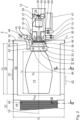
- the first device 2 comprises a rotary kiln 9 in which material is dried.
- the rotary kiln 9 has a material inlet 10 and a material outlet 11 .
- the material inlet 10 and the material outlet 11 are each arranged on the face side, ie opposite one another, on the rotary kiln 9 .
- a heating unit which has a burner 12 , is coupled to the rotary kiln 9 .
- the burner 12 is designed to burn hydrogen gas and to generate a burner flame 13 which is arranged at least in certain areas in the rotary kiln 9 .
- the burner 12 is on hydrogen burner.
- a hydrogen gas line 14 is connected to the burner 12 and is connected in particular to a hydrogen reservoir 15 .
- the hydrogen reservoir 15 is in particular a storage container, in particular a storage tank, in which hydrogen, in particular in gaseous form, is stored.
- the hydrogen reservoir 15 can also be implemented by being connected to a hydrogen supply network.
- the connection to the gas control section in the hydrogen gas line 14 takes place at a hydrogen gas distribution chamber 30 by means of a compensator 62.
- the compensator 62 is a flexible compensating element.
- the compensator 62 is used to compensate for movements in the hydrogen line 14, in particular as a result of thermal changes in length, vibrations, wall ducts and/or settlement phenomena.
- the compensator 62 is arranged at a flange connection 63 between the hydrogen distribution chamber 30 and the hydrogen gas line 14 .
- An air line 16 is connected to the burner 12 in order to supply air, in particular ambient air.
- a material conveying direction 22 through the rotary kiln 9 is directed from the material inlet 10 to the material outlet 11 and according to 1 oriented from right to left.
- a gas conveying direction 23 through the rotary kiln 9 is directed from the burner 12 to the emission line 4, ie according to FIG 1 left to right.
- the material conveying direction 22 and the gas conveying direction 23 are oriented opposite to one another.
- the rotary kiln 9 is operated in the countercurrent process.
- the rotary kiln 9 can also be operated in the cocurrent process.
- a first secondary fuel line 17 is connected to the burner in order to supply a first secondary fuel.
- fossil fuels such as natural gas, liquid gas, heating oil, coal, in particular coal dust, synthetic fuels (BtL) and/or wood dust are used as secondary fuel.
- natural gas is used as the first secondary fuel.
- the first secondary fuel line 17 is fed from a secondary fuel reservoir, not shown. Similar to the hydrogen reservoir 15, the secondary fuel reservoir can be designed as a storage container and/or as a supply network.
- the connection to the first secondary fuel line 17 and the gas control line there is made at a secondary fuel distribution chamber 32 by means of a compensator 66.
- the compensator 66 is essentially identical to the compensator 62 and is arranged at a corresponding point between the first secondary fuel line 17 and the secondary fuel distribution chamber 32.
- the burner can have a different geometry, in particular for the burner head, the baffle plate, the combustion chamber, the arrangement, number and Attachment of the nozzles used and the periphery such as an oil control line and/or a liquid gas control line applies.
- a liquid secondary fuel such as liquid gas and/or oil
- the first device 2 also has an exhaust pipe 18 which is connected to the heating unit, in particular the burner 12, and/or to the rotary kiln 9.
- the exhaust pipe 18 By means of the exhaust pipe 18 exhaust gases and / or Emissions of the heating unit and / or the rotary kiln 9 are fed.
- the exhaust line 18 basically serves as a supply line for secondary air, which can in particular be exhaust air from other emission sources, such as in particular suction from a bucket conveyor and/or a loading station.
- the secondary air is, in particular, air laden with emissions.
- the exhaust line 18 can be connected, for example, to the emission line 4 of the first device 2 and/or to the emission line 4 of the second device 3 in order to recirculate exhaust gases.
- exhaust gas sources of the asphalt mixing plant 1 can be connected to the exhaust pipe 18 .
- a separate fan 48 is arranged, which can supply additional combustion air.
- One or more flaps 49 can be arranged along the exhaust pipe 18 in order to control the air flow in a targeted manner and in particular to adjust the amounts of air added in a targeted manner.
- an air flow rate can also be regulated with the fan 48 and in particular by means of a frequency converter connected to it.
- the exhaust pipe 18 has a branched design, with a first branch opening directly into the rotary kiln 9 , in particular adjacent to the burner head 41 . Another part of the exhaust pipe 18 leads directly into the burner housing 27, in particular in the area of an annular gap 50 and/or in the area of the burner head 41.
- the rotary kiln 9 is designed such that it can be driven in rotation about an axis of rotation 19 .
- the drives required for this, in particular rotary drives, are known per se and are not shown in the figures for reasons of clarity shown.
- the rotary kiln 9 has a burnout zone 20 along the axis of rotation 19 , which extends along the axis of rotation 19 in the region of the burner flame 13 .
- the rotary kiln 9 also has a heat transfer area 21 in which heat is transferred to the material by convection.
- the second device 3 is constructed essentially identically to the first device 2, to which reference is hereby made.
- the heating unit of the second device 3 includes a hot gas generator 24 in addition to the burner 12 .
- the hot gas generator 24 is connected to the rotary kiln 9 by means of a hot gas line 25 .
- the hot gas generator 24 is arranged between the burner 12 and the rotary kiln 9 .
- the burner 12 is designed separately from the rotary kiln 9.
- the burner 12 is arranged entirely outside of the rotary kiln 9 .
- the burner flame 13 is arranged in the hot gas generator 24 .
- No burner flame is arranged in the rotary kiln 9 of the second device 3 .
- circulating air fans and/or exhaust air fans can be used for air guidance, in particular in the rotary kiln 9 and/or in the hot gas generator 24 .
- the fans are arranged in particular outside of the rotary kiln 9 and/or outside of the hot gas generator 24, in particular along connecting lines. Accordingly, a burnout zone 20 in this rotary kiln 9 is not necessary.
- the rotary kiln 9 of the second device 3 essentially exclusively comprises a heat transfer area 21.
- each device 2 , 3 has its own separate hydrogen reservoir 15 . It is also conceivable for a common, centrally arranged hydrogen reservoir 15 to be available in an asphalt mixing plant 1, which is in fluid connection with several and at least with all burners 12 of the asphalt mixing plant 1.
- the burner 12 has a burner housing 27 having a longitudinal axis 26 .
- the burner housing 27 has an intake chamber 28 at an end remote from the rotary kiln 9 , via which air, in particular ambient air, is sucked into the burner housing 27 .
- the air line 16 and/or a silencer can be connected to the intake chamber 28 .
- An air fan 29 is arranged along the burner housing 27 and is designed as an axial fan according to the exemplary embodiment shown. It goes without saying that the air fan 29 can also be designed in the manner of another type of fan, in particular as a radial fan.
- the burner 12 has in particular a flame sensor 64 which is used to monitor the burner flame 13 .
- a plurality of flame sensors 64 can be embodied on the burner 12 and, in particular, can be arranged spaced apart from one another in the burner housing 27, in particular along the longitudinal axis 26.
- a pilot burner 65 which is used to ignite the burner flame 13 .
- the hydrogen line 14 is connected to the burner housing 27 via a hydrogen gas distribution chamber 30 arranged in a ring around the burner housing 27 . At least one hydrogen gas nozzle 31 is connected to the hydrogen gas distribution chamber 30 to selectively supply the hydrogen gas into the burner body 27 . It is conceivable that no hydrogen gas distribution chamber 30 is provided. In this case, the hydrogen line 14 is connected directly to the hydrogen nozzle 31 .
- the hydrogen gas nozzle 31 is designed in particular as an annular nozzle. It is also conceivable that the hydrogen gas nozzle 31 has a different geometry and is designed in particular as a gas lance. It is also conceivable that several, in particular differently designed, hydrogen gas nozzles 31 are provided, which are arranged at different positions, in particular along the longitudinal axis 26 and/or at different positions in the circumferential direction and/or at different radial distances with respect to the longitudinal axis 26 in the burner housing 27 are.
- a secondary fuel distribution chamber 32 is connected to the first secondary fuel line 17, the function of which corresponds to that of the hydrogen gas distribution chamber 30, to which reference is hereby made.
- a plurality of secondary fuel nozzles 33 are arranged in the burner housing 27 and connected to the secondary fuel distribution chamber 32 .
- the secondary fuel nozzles 33 are each designed as gas lances and are arranged adjacent to the hydrogen nozzle 31 in the burner housing 27 .
- the first secondary fuel nozzles 33 are spaced apart in the radial direction relative to the longitudinal axis 26 in the burner housing.
- a second secondary fuel nozzle 34 is arranged in the burner housing 27 and is used for supplying liquid fuels.
- the second secondary fuel nozzle 34 is arranged in particular centrally, that is to say centrally in relation to the longitudinal axis 26 , in the burner housing 27 .
- a second secondary fuel line is connected to the second secondary fuel nozzle 34 and is shown in FIG 2 is not shown.
- the second secondary fuel nozzle 34 serves in particular for the supply of oil, in particular light oil and/or heavy oil.
- the second secondary fuel nozzle 34 is designed, for example, as a compressed air or return nozzle.
- the second secondary fuel nozzle 34 can also be designed as a ring nozzle with several liquid gas nozzles.
- the burner 12 is a combination burner, in particular a three-fuel burner, which can burn hydrogen gas, a first, in particular gaseous, secondary fuel, in particular natural gas, and a second, in particular liquid, secondary fuel, in particular light oil.
- the various fuels can be supplied to the burner 12 independently by means of its suitable control, in particular in such a way that either only one of the three fuels, in particular hydrogen, two of the three fuels or all three fuels are supplied to the burner 12 and burned there .
- a turbulence element 35 is arranged in the burner housing 27 in the area of the nozzles 31 , 33 and 34 .
- the swirling element 35 serves to swirl the air tangentially.
- the turbulence element 35 is designed in particular as a baffle plate, which in particular has a guide wheel. Depending on the fuel combination used, the baffle plate 35 can have different diameters, shapes and design details.
- the nozzles 31 , 33 , 34 are each arranged upstream of the swirling element 35 . It is possible that individual nozzles 31 , 33 , 34 , several of the nozzles or all of the nozzles are arranged downstream of the turbulence element 35 in the burner housing 27 .
- the geometry of the burner flame 13 also depends on the number and/or the position of the nozzles 31, 33 and 34.
- the different nozzles 31, 33 and 34 By using the different nozzles 31, 33 and 34, it is possible to add the different fuels separately. In particular, a time-controlled addition of the different fuels and in particular a locally separate addition of the fuels is possible.
- the quantity added and/or the time of addition is regulated by a burner control system, which is not shown in detail.
- the burner control can be carried out in a regulated manner by means of temperature monitoring using temperature sensors (not shown in detail) and/or as a function of a signal generated by the flame sensor 64 .
- a stepped addition for the hydrogen gas for example by designing the hydrogen gas nozzles as gas lances of different lengths and/or with a radially arranged gas outlet.
- the turbulence element 35 is arranged in a cooling cone 36 .
- the cooling cone 36 has a cylindrical section whose outside diameter is at least 80% of the inside diameter of the burner housing 27 at this point.
- the outer diameter of the cooling cone 36 is at least 85 %, in particular at least 90%, in particular at least 95% and in particular at most 99% of the inner diameter of the burner housing 27 at this point.
- the cooling cone 36 is arranged in particular in a region of the burner housing 27 in which the burner housing widens conically.
- the burner housing 27 has an expanding section 39 which merges into a closing section 40 .
- the closing section 40 and the widening section 39 form a burner head 41.
- a circumferential annular gap 50 is formed between an outer wall of the cooling cone 36 and an inner wall of the burner head 41.
- the air flowing through this annular gap is called secondary air.
- the secondary air thus flows past the cooling cone 36 .
- the air flowing through the cooling cone 36 is referred to as primary air. Because at least part of the air is routed past the cooling cone 36 as secondary air, air staging is possible.
- the burner head 41 improves the mixing of the fuels, in particular hydrogen with air.
- the burner flame 13 forms after the burner head 41 , the shape of the burner flame 13 being influenced by the geometry of the burner head 41 . This means that the shape of the burner flame 13 can be specifically adjusted by a suitable choice of the burner head geometry. In particular, the diameter D F of the burner flame 13 is larger, the larger the diameter at the outlet of the burner head 41 is.
- the burner 12 is attached to an end wall 42 of the rotary kiln 9 .
- the end wall 42 is referred to as the outlet end wall, since the material outlet 11 is arranged in this area.
- the burner 12, in particular the burner housing 27, is fastened to the end wall 42 by means of fastening elements which are not shown in detail.
- the end wall 42 is arranged on the rotary kiln 9 so that it overlaps, in particular in the axial direction and/or in the radial direction in relation to the axis of rotation 19 .
- the rotary kiln 9 is not hermetically sealed by the end wall 22 .
- a peripheral gap 46 remains between the end wall 42 and the rotary kiln 9. The peripheral gap 46 allows an additional supply of air, in particular ambient air.
- the burner 12 is arranged on the rotary kiln 9 in particular in such a way that the longitudinal axis 26 of the burner housing 27 and the axis of rotation 19 of the rotary kiln 9 coincide, ie are identical.
- the burner 12 is arranged concentrically to the rotary kiln 9 .
- the burner 12 is attached directly to the rotary kiln 9 and is at least partially integrated therein.
- the burner head 41 and the burner flame 13 generated by the burner 12 are arranged, in particular completely, inside the rotary kiln 9 .
- the burner 12 has a burner stand 47 with which the burner 12 is placed on a base.
- the burner frame 47 is static, that is to say immovable, in particular fixed. It is also conceivable that the burner frame has rollers on its underside, which can be rolled in particular on rails suitable for this purpose. In particular, it is conceivable that an axial displacement of the burner 12 along the rails takes place by means of an axial drive, in particular by means of a pneumatic drive.
- the burner flame 13 has a length L F and a diameter D F oriented perpendicular thereto along the longitudinal axis 26 or the axis of rotation 19 .
- the rotary kiln 9 has an inside diameter D i .
- Fire protection installations 43 are provided in the burnout zone 20 and are fastened to the inner wall of the rotary kiln 9 .
- a reduced internal diameter D red results in the burnout zone 20 as a result of the fire protection installations 43 .
- the fire protection installations 43 extend in the axial direction along a length L A which corresponds to the length of the burnout zone 20 . It is essential that the length L A of the burn-out zone 20 is greater than the length L F of the burner flame 13, and that the burner 12 is arranged on the rotary kiln 9 in such a way that the burner flame 13 is completely within the burn-out zone 20, in particular in the axial direction on the axis of rotation 19, is arranged. Furthermore, it is essential that the diameter D F of the burner flame 13 is smaller than the reduced diameter D red . A direct flame contact of the fire protection installations 43 is avoided.
- Throwing plates 44 are arranged in the heat transfer area 21 and are fastened in particular to the inside of the rotary kiln 9 .
- the throwing plates 44 are designed to be open and are used to produce a veil of material 45. It is particularly advantageous if the veil of material is as dense as possible. It is possible to indirectly quantify the density of the material veil 45, in particular by measuring the exhaust gas temperature. The lower the exhaust gas temperature, the greater the heat transfer to the material that previously took place. This means that the material veil 45 is all the denser, the lower the exhaust gas temperature will be and vice versa.
- the flue gas temperature results from the burner output, the pre-metering output, So the mass flow of the supplied material in the rotary kiln 9, and the material temperature.
- the material temperature is used in particular as an input variable for controlling the burner output. It was found that it is advantageous if the exhaust gas temperature is at least 100° C. in the exemplary embodiment shown. It goes without saying that depending on the material used, the burner 12 used or the fuel used, the exhaust gas temperature for monitoring the material curtain 45 can assume other values.
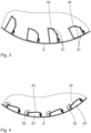
- the following is based on 3 the geometry of the throwing plates 44 is explained in more detail. It is possible that different geometries of throwing plates are used. According to the illustration shown, two different throwing plate geometries are arranged alternately and at a distance from one another along the circumferential direction.
- the individual throwing plates 44 are fastened to the inside of the rotary kiln 9 by means of a holding element, in particular a holding bracket.
- the throwing plates 44 are so-called open installations and are designed in particular like shovels.
- the throwing plates 44 have multiple edges, ie they have at least two edges 51 . When the rotary kiln 9 is in operation, the throwing plates 44 pick up the material to be dried and release it again in an upper area when the rotary kiln 9 rotates.
- the throwing plates 44 are designed in such a way that a veil of material 45 that is as dense, continuous and homogeneous as possible is formed.
- the material veil 45 has a particularly large surface area, as a result of which the heat transfer through convection is improved.
- the specific geometry of the throwing plates 44 and in particular their arrangement on the inside of the rotary kiln 9 can at different Materials, different material moisture levels and/or drying performance vary in order to produce a material veil 45 that is as dense as possible. For example, when drying recycled asphalt, rake-like installations, radially aligned half-shells or other geometries can be advantageous for creating the material veil.
- the background is that depending on the material used, its moisture content and/or the drying capacity of the rotary kiln 9, the discharge characteristics from the throwing plates 44 can vary.
- the fire protection installations 43 are closed installations, i.e. form as in 4 shown, a substantially C-shaped frame, which is arranged with its open side on the rotary kiln 9 and thereby closed.
- Each fire protection installation 43 and the corresponding section of the rotary kiln 9 form a closed chamber 67, which is only in the axial direction, ie perpendicular to the plane of the 4 is open.
- the fire protection installations 43 are each held by means of a holding clip 52 .
- the material placed in chamber 67 is protected. This avoids direct contact with the burner flame 13 in the burnout zone.
- the material is indirectly transferred from the surface of the fire protection fittings 43 into the material by thermal radiation.
- the fire protection installations 43, the throwing plates 44 and the rotary kiln 9 as a whole are made of heat-resistant and wear-resistant material.
- the turbulence element 35 is designed as a baffle plate.
- the main function of the baffle plate 35 is to swirl the air arriving along the longitudinal axis 26, ie the primary air, tangentially.
- the baffle plate 35 is arranged concentrically to the longitudinal axis 26 in the burner housing 27 .
- the catchment disk 35 has a plurality of blades 53,54.
- the inner blades 53 are arranged overlapping one another in a circular manner in the circumferential direction about the longitudinal axis 26 . According to the embodiment shown, sixteen blades 53 are arranged.
- a central passage opening 55 remains in a central region surrounded by the inner blades 53 .
- the inner blades 53 have a transverse web 56 which is oriented perpendicularly to the longitudinal axis 26 .
- the transverse web 56 is connected in one piece to a diagonal web 58 via the edge 57 .
- the transverse web 56 and the diagonal web 58 enclose an opening angle that is greater than 90° and smaller than 180°, in particular between 120° and 150°.
- the inner blades 53 are held in an inner ring 59 .
- the inner ring 59 is surrounded by outer blades 54 which are held on an outer ring 60 on their outside.
- the outer ring 60 projects in the axial direction relative to the longitudinal axis 26 on the inner ring 59 in both directions.
- the outer blades 54 are in particular designed without edging, ie they have a planar, planar geometry.
- a middle ring 61 is placed axially between the inner ring 59 and the outer ring 60 with respect to the radical direction.
- the catchment disk 35 has an inflow surface that is divided into three.
- the face surface includes the inner central region formed by passage 55 and inner vanes 53 and closed by inner ring 59 .
- the second secondary fuel nozzle 34 for oil is arranged in this area.
- a second section results in the radial direction between the inner ring 59 and the middle ring 61.
- the first secondary fuel nozzles 33 for gas, in particular natural gas, are arranged in this area.
- the outer blades 54 are oriented inclined relative to the longitudinal axis 26 and in particular are arranged in a plane which essentially corresponds to the plane of the corresponding diagonal webs 58 of the inner blades 53 .
- An outer, in particular ring-shaped section between the middle ring 61 and the outer ring 60 can be flown by the hydrogen nozzle 31 designed as a ring nozzle.
- material can be fed to the rotary kiln 9 via the material inlet 10 .
- the material is conveyed along the material conveying direction 22 at the material inlet 10 by means of the conveying elements (not shown in detail), which are designed in particular as inlet screw segments and are fastened to the inner wall of the rotary kiln.
- a dense, continuous and homogeneous veil of material 45 is produced in the heat transfer area 21 due to the special design of the throwing plates 44 , so that the material is arranged with a very large surface inside the rotary kiln 9 .
- the material can be heated by convection by means of the burner flame 13 , which is arranged directly in the rotary kiln 9 .
- the burner flame 13 is generated by the burner 12, which is designed as a combination burner and burns hydrogen gas as the primary fuel. Natural gas and light oil in particular are used as secondary fuels. It goes without saying that secondary fuels that differ from this can also be used, in particular only one secondary fuel or more than two secondary fuels.
- the burner 12 can also be operated without secondary fuels and/or exclusively using secondary fuels. Because hydrogen gas is used as the primary fuel, exhaust gases and/or emissions are reduced and, in particular, avoided. Due to the fact that exhaust gases and/or emission-laden air are supplied via the exhaust gas line 18 and also burned, the exhaust gases are reduced overall.
- closed fire protection installations 43 are arranged in the burnout zone 20 in the rotary kiln 9 in which the burner flame 13 is arranged, direct material contact with the burner flame 13 is avoided. It is essential that the burner flame 13 can be specifically adjusted due to the geometry of the burner head 41 and/or the baffle plate 35, the number, arrangement and design of the fuel nozzles 31, 33 and/or 34 so that it is arranged completely within the burnout zone 20 in the rotary kiln 9 is.
- the cooling cone 36 and the annular gap 50 formed between the cooling cone 36 and the burner housing 27 create the prerequisite for air staging. Secondary air is guided past the baffle plate 35 and around the burner flame 13 .
- the flame temperature is kept as low as possible, in particular at less than 1400° C., so that the formation of nitrogen oxides (NO x ) is minimized and in particular avoided.
- the inner diameter D I of the rotary kiln 9 is selected in particular in such a way that the flow rate of the resulting exhaust gas volume flows of the various fuels is so low that only filler, i.e. rock dust with a particle size of at most 200 ⁇ m, is discharged from the rotary kiln 9.
- the flow rate is less than 20m/s and in particular between 15m/s and 20m/s. It is advantageous if the flow rate and/or the volume flow of the exhaust gas is kept low. As a result, wear and tear in the raw gas ducts and/or in an exhaust line can be reduced and, in particular, minimized.
Landscapes
- Engineering & Computer Science (AREA)
- Mechanical Engineering (AREA)
- General Engineering & Computer Science (AREA)
- Combustion & Propulsion (AREA)
- Chemical & Material Sciences (AREA)
- Life Sciences & Earth Sciences (AREA)
- Sustainable Development (AREA)
- Thermal Sciences (AREA)
- Physics & Mathematics (AREA)
- Architecture (AREA)
- Civil Engineering (AREA)
- Structural Engineering (AREA)
- Muffle Furnaces And Rotary Kilns (AREA)
- Road Paving Machines (AREA)
- Drying Of Solid Materials (AREA)
Applications Claiming Priority (1)
| Application Number | Priority Date | Filing Date | Title |
|---|---|---|---|
| DE102021210662.5A DE102021210662B4 (de) | 2021-09-24 | 2021-09-24 | Vorrichtung und Verfahren zum Trocknen von Material sowie Asphaltmischanlage mit einer derartigen Vorrichtung |
Publications (1)
| Publication Number | Publication Date |
|---|---|
| EP4155643A1 true EP4155643A1 (fr) | 2023-03-29 |
Family
ID=82943070
Family Applications (1)
| Application Number | Title | Priority Date | Filing Date |
|---|---|---|---|
| EP22190889.0A Pending EP4155643A1 (fr) | 2021-09-24 | 2022-08-18 | Dispositif et procédé de séchage de matériau, ainsi qu'installation de mélange d'asphalte doté d'un tel dispositif |
Country Status (3)
| Country | Link |
|---|---|
| US (1) | US12474118B2 (fr) |
| EP (1) | EP4155643A1 (fr) |
| DE (2) | DE102021210662B4 (fr) |
Families Citing this family (3)
| Publication number | Priority date | Publication date | Assignee | Title |
|---|---|---|---|---|
| DE102021210662B4 (de) * | 2021-09-24 | 2025-07-10 | Benninghoven Zweigniederlassung Der Wirtgen Mineral Technologies Gmbh | Vorrichtung und Verfahren zum Trocknen von Material sowie Asphaltmischanlage mit einer derartigen Vorrichtung |
| DE102023202662B3 (de) | 2023-03-23 | 2024-07-18 | Benninghoven Zweigniederlassung Der Wirtgen Mineral Technologies Gmbh | Brenner-Vorrichtung für eine Anlage zur Herstellung von Asphalt und Anlage mit einer derartigen Brenner-Vorrichtung |
| DE102024202664A1 (de) | 2024-03-20 | 2025-09-25 | Benninghoven Zweigniederlassung Der Wirtgen Mineral Technologies Gmbh | Anlage und Verfahren zur Materialtrocknung für die Herstellung von Asphalt |
Citations (14)
| Publication number | Priority date | Publication date | Assignee | Title |
|---|---|---|---|---|
| EP0340462A1 (fr) * | 1988-05-04 | 1989-11-08 | Deutag Asphalttechnik GmbH | Four à tambour rotatif pour sécher ou mélanger des matériaux susceptibles de couler ou de ruisseler |
| EP0580127A1 (fr) * | 1992-07-21 | 1994-01-26 | Mitsubishi Chemical Corporation | Procédé et dispositif de séchage de poudre et matériau granuleux |
| EP0600525A2 (fr) * | 1993-05-18 | 1994-06-08 | U. Ammann Maschinenfabrik AG | Procédé et installation pour le séchage, et/ou le chauffage de matériaux pouvant s'écouler |
| DE4243264A1 (de) * | 1992-12-19 | 1994-06-23 | Deutag Ag | Drehofen zum Trocknen und/oder Mischen von rieselfähigem Material |
| CA2184918A1 (fr) * | 1994-03-07 | 1995-09-14 | Malcolm L. Swanson | Poste d'enrobage a tambour secheur, comportant une chambre de recirculation destinee a reduire les emissions de cov et de nox |
| WO2003098110A1 (fr) * | 2002-05-16 | 2003-11-27 | Alstom Technology Ltd | Bruleur a premelange |
| US20040219466A1 (en) * | 2003-05-02 | 2004-11-04 | Marino John A. | Aggregate dryer burner with compressed air oil atomizer |
| WO2006058843A1 (fr) * | 2004-11-30 | 2006-06-08 | Alstom Technology Ltd | Procede et dispositif de combustion d'hydrogene dans un bruleur a premelange |
| US20090123882A1 (en) * | 2007-11-09 | 2009-05-14 | Alstom Technology Ltd | Method for operating a burner |
| WO2009109454A1 (fr) * | 2008-03-07 | 2009-09-11 | Alstom Technology Ltd | Procédé et ensemble brûleur servant à produire du gaz chaud et utilisation dudit procédé |
| JP2009293859A (ja) * | 2008-06-05 | 2009-12-17 | Nippo Corp | 無機質粉粒体の加熱乾燥方法 |
| DE202010002774U1 (de) * | 2010-02-25 | 2010-07-15 | Ammann Schweiz Ag | Brenner |
| KR20100120579A (ko) * | 2009-05-06 | 2010-11-16 | 김상남 | 브라운가스 슈팅 버너건을 이용한 연소촉진시스템 |
| CN210512434U (zh) * | 2019-09-27 | 2020-05-12 | 成都市路桥工程股份有限公司 | 一种节能环保型道路桥梁用沥青骨料干燥系统 |
Family Cites Families (19)
| Publication number | Priority date | Publication date | Assignee | Title |
|---|---|---|---|---|
| DE19530164A1 (de) | 1995-08-03 | 1997-02-06 | Teltomat Maschinen Gmbh | Trockentrommel zur Aufbereitung von Asphaltgranulat |
| US6309211B1 (en) * | 2000-06-13 | 2001-10-30 | Suedala Industries, Inc. | Port air conveying system for rotary kiln |
| EP1785202A1 (fr) | 2005-11-11 | 2007-05-16 | Roman Daub | Dispositif et procédé pour nettoyer des matières contaminées |
| DE102010001055A1 (de) | 2010-01-20 | 2011-07-21 | Benninghoven GmbH & Co.KG Mülheim, 54486 | System zur Wärmerückgewinnung an einem Drehrohrofen |
| GB2502255B (en) * | 2012-04-23 | 2018-02-28 | Brian Lewis Ian | A fuel valve for connecting a burner to two separate fuel supplies |
| DE102013224910A1 (de) | 2013-12-04 | 2015-06-11 | Benninghoven GmbH & Co. KG Mülheim | Vorrichtung und Verfahren zum Erwärmen von Altasphalt-Granulat zur Herstellung von Asphalt |
| DE102015222284A1 (de) * | 2015-11-12 | 2017-05-18 | Benninghoven GmbH & Co. KG Mülheim | Anlage und Verfahren zum Herstellen von Asphalt |
| EP3196177A1 (fr) | 2016-01-21 | 2017-07-26 | HeidelbergCement AG | Hydrogene comme combustible dans la fabrication de ciment |
| ES2693606T3 (es) * | 2016-09-16 | 2018-12-12 | Benninghoven GmbH & Co.KG Mülheim | Planta y procedimiento para la fabricación de asfalto |
| CN206073075U (zh) * | 2016-09-28 | 2017-04-05 | 杭州全合科技有限公司 | 一种大流量的高温粗煤气燃烧器 |
| FR3062468B1 (fr) * | 2017-01-27 | 2020-10-02 | Ermont | Secheur a tambour rotatif pour le sechage de granulats |
| FR3067371B1 (fr) * | 2017-06-09 | 2021-11-26 | Ermont | Installation et procede de production d'enrobes |
| DE102018203196A1 (de) * | 2018-03-02 | 2019-09-05 | Benninghoven Gmbh & Co. Kg | Verfahren zum Bereitstellen eines geregelten Unterdrucks in mindestens einer Trockentrommel einer Anlage zur Asphaltherstellung sowie derartige Anlage zur Asphaltherstellung |
| DE102018108802B3 (de) | 2018-04-13 | 2019-09-12 | Khd Humboldt Wedag Gmbh | Anlage zur wahlweisen Herstellung von Zementklinker für grauen oder weißen Zement |
| EP3833918A1 (fr) * | 2018-08-07 | 2021-06-16 | Novelis, Inc. | Raclette de four réglable pour dispositif de décapage de four rotatif et procédé associé |
| CN210176888U (zh) * | 2019-07-17 | 2020-03-24 | 圣航粉末冶金河北有限公司 | 一种间接加热氢气回转窑直接还原高纯铁系统 |
| CN110295263A (zh) * | 2019-07-17 | 2019-10-01 | 圣航粉末冶金河北有限公司 | 一种间接加热氢气回转窑直接还原高纯铁的方法 |
| DE102021210662B4 (de) * | 2021-09-24 | 2025-07-10 | Benninghoven Zweigniederlassung Der Wirtgen Mineral Technologies Gmbh | Vorrichtung und Verfahren zum Trocknen von Material sowie Asphaltmischanlage mit einer derartigen Vorrichtung |
| DE102023005401A1 (de) * | 2023-03-23 | 2024-09-26 | Benninghoven Zweigniederlassung Der Wirtgen Mineral Technologies Gmbh | Brenner-Vorrichtung für eine Anlage zur Herstellung von Asphalt, Anlage mit einer derartigen Brenner-Vorrichtung sowie Verfahren von Zuführen von Wärme in einen Drehrohrofen einerBrenner-Vorrichtung |
-
2021
- 2021-09-24 DE DE102021210662.5A patent/DE102021210662B4/de active Active
-
2022
- 2022-08-18 DE DE202022003202.1U patent/DE202022003202U1/de active Active
- 2022-08-18 EP EP22190889.0A patent/EP4155643A1/fr active Pending
- 2022-09-23 US US17/951,209 patent/US12474118B2/en active Active
Patent Citations (14)
| Publication number | Priority date | Publication date | Assignee | Title |
|---|---|---|---|---|
| EP0340462A1 (fr) * | 1988-05-04 | 1989-11-08 | Deutag Asphalttechnik GmbH | Four à tambour rotatif pour sécher ou mélanger des matériaux susceptibles de couler ou de ruisseler |
| EP0580127A1 (fr) * | 1992-07-21 | 1994-01-26 | Mitsubishi Chemical Corporation | Procédé et dispositif de séchage de poudre et matériau granuleux |
| DE4243264A1 (de) * | 1992-12-19 | 1994-06-23 | Deutag Ag | Drehofen zum Trocknen und/oder Mischen von rieselfähigem Material |
| EP0600525A2 (fr) * | 1993-05-18 | 1994-06-08 | U. Ammann Maschinenfabrik AG | Procédé et installation pour le séchage, et/ou le chauffage de matériaux pouvant s'écouler |
| CA2184918A1 (fr) * | 1994-03-07 | 1995-09-14 | Malcolm L. Swanson | Poste d'enrobage a tambour secheur, comportant une chambre de recirculation destinee a reduire les emissions de cov et de nox |
| WO2003098110A1 (fr) * | 2002-05-16 | 2003-11-27 | Alstom Technology Ltd | Bruleur a premelange |
| US20040219466A1 (en) * | 2003-05-02 | 2004-11-04 | Marino John A. | Aggregate dryer burner with compressed air oil atomizer |
| WO2006058843A1 (fr) * | 2004-11-30 | 2006-06-08 | Alstom Technology Ltd | Procede et dispositif de combustion d'hydrogene dans un bruleur a premelange |
| US20090123882A1 (en) * | 2007-11-09 | 2009-05-14 | Alstom Technology Ltd | Method for operating a burner |
| WO2009109454A1 (fr) * | 2008-03-07 | 2009-09-11 | Alstom Technology Ltd | Procédé et ensemble brûleur servant à produire du gaz chaud et utilisation dudit procédé |
| JP2009293859A (ja) * | 2008-06-05 | 2009-12-17 | Nippo Corp | 無機質粉粒体の加熱乾燥方法 |
| KR20100120579A (ko) * | 2009-05-06 | 2010-11-16 | 김상남 | 브라운가스 슈팅 버너건을 이용한 연소촉진시스템 |
| DE202010002774U1 (de) * | 2010-02-25 | 2010-07-15 | Ammann Schweiz Ag | Brenner |
| CN210512434U (zh) * | 2019-09-27 | 2020-05-12 | 成都市路桥工程股份有限公司 | 一种节能环保型道路桥梁用沥青骨料干燥系统 |
Also Published As
| Publication number | Publication date |
|---|---|
| US20230098621A1 (en) | 2023-03-30 |
| DE102021210662A1 (de) | 2023-03-30 |
| US12474118B2 (en) | 2025-11-18 |
| DE102021210662B4 (de) | 2025-07-10 |
| DE202022003202U1 (de) | 2025-05-27 |
Similar Documents
| Publication | Publication Date | Title |
|---|---|---|
| EP4155643A1 (fr) | Dispositif et procédé de séchage de matériau, ainsi qu'installation de mélange d'asphalte doté d'un tel dispositif | |
| EP3789672B1 (fr) | Installation de chauffage à la biomasse ayant une conduite d'air secondaire, ainsi que ses parties intégrantes | |
| EP3889502B1 (fr) | Agencement de combustion pour installation de chauffage à la biomasse | |
| DE2619316C2 (de) | Müllverbrennungsvorrichtung | |
| DE102007030269A1 (de) | Kohlenstaubbrenner zur Verfeuerung von in Dichtstromförderung zugeführten Brennstoff | |
| DE2231001A1 (de) | Muellverbrennungsofen | |
| DE2732344A1 (de) | Gasturbinenmaschine | |
| EP2691701B1 (fr) | Procédé d'optimisation de la combustion totale des gaz d'échappement d'une installation de combustion | |
| DE2745756C3 (de) | Verbrennungsofen | |
| EP0952396B1 (fr) | Dispositif pour brûler des matériaux combustibles particulaires | |
| EP3327349B1 (fr) | Générateur de gaz chaud permettant de chauffer un gaz ainsi qu'installation pour la production de bitume pourvue d'un tel générateur de gaz chaud | |
| DE102023005401A1 (de) | Brenner-Vorrichtung für eine Anlage zur Herstellung von Asphalt, Anlage mit einer derartigen Brenner-Vorrichtung sowie Verfahren von Zuführen von Wärme in einen Drehrohrofen einerBrenner-Vorrichtung | |
| EP1052231A1 (fr) | Procédé et dispositif de traitement de farine crue | |
| DE4402172A1 (de) | Verfahren zur Verbrennung von Brennstoff und Anlage zur Durchführung des Verfahrens | |
| DE102023202665B3 (de) | Düsenanordnung für einen Brenner sowie Brenner mit einer derartigen Düsenanordnung | |
| DE102023202662B3 (de) | Brenner-Vorrichtung für eine Anlage zur Herstellung von Asphalt und Anlage mit einer derartigen Brenner-Vorrichtung | |
| EP0006974B1 (fr) | Brûleur pour la combustion du charbon broyé | |
| DE102023005399A1 (de) | Düsenanordnung für einen Brenner sowie Brenner mit einer derartigen Düsenanordnung | |
| WO1982000331A1 (fr) | Generateur de gaz chaud | |
| DE3309905C2 (de) | Verfahren und Vorrichtung zum Verbrennen fester Brennstoffe in pulverisierter Form | |
| EP0952398B1 (fr) | Procédé et dispositif d'alimentation en air pour brûler du combustible particulaire | |
| DE4125047A1 (de) | Vorrichtung zur heissgasmischung und staubreduzierung in brennkammern | |
| EP1122495B1 (fr) | Dispositif pour l'incinération de matière biomasse particulaire et solide | |
| DE4439565C2 (de) | Ventilvorrichtung für die dosierte Einleitung von Feinstasche in einen Wirbelschichtreaktor | |
| DE102010051601A1 (de) | Heizkessel |
Legal Events
| Date | Code | Title | Description |
|---|---|---|---|
| PUAI | Public reference made under article 153(3) epc to a published international application that has entered the european phase |
Free format text: ORIGINAL CODE: 0009012 |
|
| STAA | Information on the status of an ep patent application or granted ep patent |
Free format text: STATUS: THE APPLICATION HAS BEEN PUBLISHED |
|
| AK | Designated contracting states |
Kind code of ref document: A1 Designated state(s): AL AT BE BG CH CY CZ DE DK EE ES FI FR GB GR HR HU IE IS IT LI LT LU LV MC MK MT NL NO PL PT RO RS SE SI SK SM TR |
|
| STAA | Information on the status of an ep patent application or granted ep patent |
Free format text: STATUS: REQUEST FOR EXAMINATION WAS MADE |
|
| 17P | Request for examination filed |
Effective date: 20230411 |
|
| RBV | Designated contracting states (corrected) |
Designated state(s): AL AT BE BG CH CY CZ DE DK EE ES FI FR GB GR HR HU IE IS IT LI LT LU LV MC MK MT NL NO PL PT RO RS SE SI SK SM TR |
|
| STAA | Information on the status of an ep patent application or granted ep patent |
Free format text: STATUS: EXAMINATION IS IN PROGRESS |
|
| 17Q | First examination report despatched |
Effective date: 20240115 |