EP4156391A1 - Busbar für ein batteriemodul oder ein stapelbatteriepack für flexible batterien zur elektrischen verbindung mindestens eines akkumulators des moduls oder pakets, verfahren zur herstellung eines batteriemoduls oder eines batteriepacks - Google Patents
Busbar für ein batteriemodul oder ein stapelbatteriepack für flexible batterien zur elektrischen verbindung mindestens eines akkumulators des moduls oder pakets, verfahren zur herstellung eines batteriemoduls oder eines batteriepacks Download PDFInfo
- Publication number
- EP4156391A1 EP4156391A1 EP22197211.0A EP22197211A EP4156391A1 EP 4156391 A1 EP4156391 A1 EP 4156391A1 EP 22197211 A EP22197211 A EP 22197211A EP 4156391 A1 EP4156391 A1 EP 4156391A1
- Authority
- EP
- European Patent Office
- Prior art keywords
- clamping
- busbar
- battery
- cathode
- battery module
- Prior art date
- Legal status (The legal status is an assumption and is not a legal conclusion. Google has not performed a legal analysis and makes no representation as to the accuracy of the status listed.)
- Pending
Links
- 238000009459 flexible packaging Methods 0.000 title claims abstract description 20
- 238000000034 method Methods 0.000 title abstract description 11
- 230000006835 compression Effects 0.000 claims description 16
- 238000007906 compression Methods 0.000 claims description 16
- 229910001416 lithium ion Inorganic materials 0.000 claims description 16
- 229910052782 aluminium Inorganic materials 0.000 claims description 13
- XAGFODPZIPBFFR-UHFFFAOYSA-N aluminium Chemical compound [Al] XAGFODPZIPBFFR-UHFFFAOYSA-N 0.000 claims description 13
- RYGMFSIKBFXOCR-UHFFFAOYSA-N Copper Chemical compound [Cu] RYGMFSIKBFXOCR-UHFFFAOYSA-N 0.000 claims description 11
- 239000010949 copper Substances 0.000 claims description 10
- 229910052802 copper Inorganic materials 0.000 claims description 10
- OKTJSMMVPCPJKN-UHFFFAOYSA-N Carbon Chemical compound [C] OKTJSMMVPCPJKN-UHFFFAOYSA-N 0.000 claims description 9
- 229910002804 graphite Inorganic materials 0.000 claims description 8
- 239000010439 graphite Substances 0.000 claims description 8
- 239000003792 electrolyte Substances 0.000 claims description 7
- 230000009471 action Effects 0.000 claims description 6
- 238000007373 indentation Methods 0.000 claims description 6
- WHXSMMKQMYFTQS-UHFFFAOYSA-N Lithium Chemical compound [Li] WHXSMMKQMYFTQS-UHFFFAOYSA-N 0.000 claims description 5
- RTAQQCXQSZGOHL-UHFFFAOYSA-N Titanium Chemical compound [Ti] RTAQQCXQSZGOHL-UHFFFAOYSA-N 0.000 claims description 5
- 238000006073 displacement reaction Methods 0.000 claims description 5
- 229910052744 lithium Inorganic materials 0.000 claims description 5
- 230000000284 resting effect Effects 0.000 claims description 5
- CIWBSHSKHKDKBQ-JLAZNSOCSA-N Ascorbic acid Chemical compound OC[C@H](O)[C@H]1OC(=O)C(O)=C1O CIWBSHSKHKDKBQ-JLAZNSOCSA-N 0.000 claims description 4
- 229910002992 LiNi0.33Mn0.33Co0.33O2 Inorganic materials 0.000 claims description 4
- 238000004519 manufacturing process Methods 0.000 claims description 4
- 229910012851 LiCoO 2 Inorganic materials 0.000 claims description 3
- 229910010707 LiFePO 4 Inorganic materials 0.000 claims description 3
- 238000003825 pressing Methods 0.000 claims description 3
- 239000004411 aluminium Substances 0.000 claims description 2
- 238000007789 sealing Methods 0.000 claims description 2
- 239000007773 negative electrode material Substances 0.000 claims 1
- 239000007774 positive electrode material Substances 0.000 claims 1
- 210000002105 tongue Anatomy 0.000 abstract description 16
- 241000920340 Pion Species 0.000 description 21
- 239000000463 material Substances 0.000 description 12
- 208000031968 Cadaver Diseases 0.000 description 10
- HBBGRARXTFLTSG-UHFFFAOYSA-N Lithium ion Chemical compound [Li+] HBBGRARXTFLTSG-UHFFFAOYSA-N 0.000 description 10
- 230000010354 integration Effects 0.000 description 6
- 229910052751 metal Inorganic materials 0.000 description 6
- 239000002184 metal Substances 0.000 description 6
- 238000003466 welding Methods 0.000 description 6
- 239000002131 composite material Substances 0.000 description 5
- PXHVJJICTQNCMI-UHFFFAOYSA-N Nickel Chemical compound [Ni] PXHVJJICTQNCMI-UHFFFAOYSA-N 0.000 description 4
- XUIMIQQOPSSXEZ-UHFFFAOYSA-N Silicon Chemical compound [Si] XUIMIQQOPSSXEZ-UHFFFAOYSA-N 0.000 description 4
- 238000004806 packaging method and process Methods 0.000 description 4
- 229920000642 polymer Polymers 0.000 description 4
- 229910052710 silicon Inorganic materials 0.000 description 4
- 239000010703 silicon Substances 0.000 description 4
- 241001080024 Telles Species 0.000 description 3
- 230000008901 benefit Effects 0.000 description 3
- 238000003780 insertion Methods 0.000 description 3
- 230000037431 insertion Effects 0.000 description 3
- 229910021645 metal ion Inorganic materials 0.000 description 3
- 230000008569 process Effects 0.000 description 3
- 101100536354 Drosophila melanogaster tant gene Proteins 0.000 description 2
- 239000004952 Polyamide Substances 0.000 description 2
- 239000004698 Polyethylene Substances 0.000 description 2
- 239000000654 additive Substances 0.000 description 2
- 239000000470 constituent Substances 0.000 description 2
- 230000002950 deficient Effects 0.000 description 2
- 238000013461 design Methods 0.000 description 2
- 230000001066 destructive effect Effects 0.000 description 2
- 230000002349 favourable effect Effects 0.000 description 2
- 239000011888 foil Substances 0.000 description 2
- AMWRITDGCCNYAT-UHFFFAOYSA-L hydroxy(oxo)manganese;manganese Chemical compound [Mn].O[Mn]=O.O[Mn]=O AMWRITDGCCNYAT-UHFFFAOYSA-L 0.000 description 2
- 238000007654 immersion Methods 0.000 description 2
- 238000003754 machining Methods 0.000 description 2
- 238000012423 maintenance Methods 0.000 description 2
- 229910052759 nickel Inorganic materials 0.000 description 2
- 229920002647 polyamide Polymers 0.000 description 2
- 229920000573 polyethylene Polymers 0.000 description 2
- 229910001415 sodium ion Inorganic materials 0.000 description 2
- 239000010935 stainless steel Substances 0.000 description 2
- 229910001220 stainless steel Inorganic materials 0.000 description 2
- 238000004804 winding Methods 0.000 description 2
- 238000010146 3D printing Methods 0.000 description 1
- 229910000838 Al alloy Inorganic materials 0.000 description 1
- 229910010490 Li4TiO5O12 Inorganic materials 0.000 description 1
- 229910032387 LiCoO2 Inorganic materials 0.000 description 1
- 229910052493 LiFePO4 Inorganic materials 0.000 description 1
- 229910015643 LiMn 2 O 4 Inorganic materials 0.000 description 1
- 229910002995 LiNi0.8Co0.15Al0.05O2 Inorganic materials 0.000 description 1
- 229910013410 LiNixCoyAlzO2 Inorganic materials 0.000 description 1
- 229910013710 LiNixMnyCozO2 Inorganic materials 0.000 description 1
- 229910001290 LiPF6 Inorganic materials 0.000 description 1
- JLVVSXFLKOJNIY-UHFFFAOYSA-N Magnesium ion Chemical compound [Mg+2] JLVVSXFLKOJNIY-UHFFFAOYSA-N 0.000 description 1
- 206010063493 Premature ageing Diseases 0.000 description 1
- FKNQFGJONOIPTF-UHFFFAOYSA-N Sodium cation Chemical compound [Na+] FKNQFGJONOIPTF-UHFFFAOYSA-N 0.000 description 1
- ATJFFYVFTNAWJD-UHFFFAOYSA-N Tin Chemical compound [Sn] ATJFFYVFTNAWJD-UHFFFAOYSA-N 0.000 description 1
- 239000004676 acrylonitrile butadiene styrene Substances 0.000 description 1
- 230000000996 additive effect Effects 0.000 description 1
- 238000004026 adhesive bonding Methods 0.000 description 1
- 239000012790 adhesive layer Substances 0.000 description 1
- 229910045601 alloy Inorganic materials 0.000 description 1
- 239000000956 alloy Substances 0.000 description 1
- ACKHWUITNXEGEP-UHFFFAOYSA-N aluminum cobalt(2+) nickel(2+) oxygen(2-) Chemical compound [O-2].[Al+3].[Co+2].[Ni+2] ACKHWUITNXEGEP-UHFFFAOYSA-N 0.000 description 1
- 239000011324 bead Substances 0.000 description 1
- 238000005452 bending Methods 0.000 description 1
- 229910052799 carbon Inorganic materials 0.000 description 1
- 150000004649 carbonic acid derivatives Chemical class 0.000 description 1
- 229910000428 cobalt oxide Inorganic materials 0.000 description 1
- IVMYJDGYRUAWML-UHFFFAOYSA-N cobalt(ii) oxide Chemical compound [Co]=O IVMYJDGYRUAWML-UHFFFAOYSA-N 0.000 description 1
- 230000000295 complement effect Effects 0.000 description 1
- 239000002482 conductive additive Substances 0.000 description 1
- 230000007547 defect Effects 0.000 description 1
- 238000009826 distribution Methods 0.000 description 1
- 238000005553 drilling Methods 0.000 description 1
- 239000007772 electrode material Substances 0.000 description 1
- 230000008030 elimination Effects 0.000 description 1
- 238000003379 elimination reaction Methods 0.000 description 1
- 238000005516 engineering process Methods 0.000 description 1
- 239000000499 gel Substances 0.000 description 1
- 230000003116 impacting effect Effects 0.000 description 1
- 239000002608 ionic liquid Substances 0.000 description 1
- 229910000398 iron phosphate Inorganic materials 0.000 description 1
- WBJZTOZJJYAKHQ-UHFFFAOYSA-K iron(3+) phosphate Chemical compound [Fe+3].[O-]P([O-])([O-])=O WBJZTOZJJYAKHQ-UHFFFAOYSA-K 0.000 description 1
- 239000010410 layer Substances 0.000 description 1
- 239000007788 liquid Substances 0.000 description 1
- 239000011244 liquid electrolyte Substances 0.000 description 1
- 229940006487 lithium cation Drugs 0.000 description 1
- 229910003002 lithium salt Inorganic materials 0.000 description 1
- 159000000002 lithium salts Chemical class 0.000 description 1
- 229910001425 magnesium ion Inorganic materials 0.000 description 1
- 239000007769 metal material Substances 0.000 description 1
- 239000000203 mixture Substances 0.000 description 1
- 238000000465 moulding Methods 0.000 description 1
- 239000011185 multilayer composite material Substances 0.000 description 1
- 239000005486 organic electrolyte Substances 0.000 description 1
- 239000003960 organic solvent Substances 0.000 description 1
- -1 polyethylene Polymers 0.000 description 1
- 229920006254 polymer film Polymers 0.000 description 1
- 229920002635 polyurethane Polymers 0.000 description 1
- 239000004814 polyurethane Substances 0.000 description 1
- 239000000843 powder Substances 0.000 description 1
- QQONPFPTGQHPMA-UHFFFAOYSA-N propylene Natural products CC=C QQONPFPTGQHPMA-UHFFFAOYSA-N 0.000 description 1
- 125000004805 propylene group Chemical group [H]C([H])([H])C([H])([*:1])C([H])([H])[*:2] 0.000 description 1
- 238000004064 recycling Methods 0.000 description 1
- 238000005096 rolling process Methods 0.000 description 1
- 238000005245 sintering Methods 0.000 description 1
- 239000007787 solid Substances 0.000 description 1
- 239000007784 solid electrolyte Substances 0.000 description 1
- 238000003860 storage Methods 0.000 description 1
- 230000001629 suppression Effects 0.000 description 1
- 239000010409 thin film Substances 0.000 description 1
- 229910000314 transition metal oxide Inorganic materials 0.000 description 1
- 238000013519 translation Methods 0.000 description 1
Images


Classifications
-
- H—ELECTRICITY
- H01—ELECTRIC ELEMENTS
- H01M—PROCESSES OR MEANS, e.g. BATTERIES, FOR THE DIRECT CONVERSION OF CHEMICAL ENERGY INTO ELECTRICAL ENERGY
- H01M50/00—Constructional details or processes of manufacture of the non-active parts of electrochemical cells other than fuel cells, e.g. hybrid cells
- H01M50/20—Mountings; Secondary casings or frames; Racks, modules or packs; Suspension devices; Shock absorbers; Transport or carrying devices; Holders
- H01M50/204—Racks, modules or packs for multiple batteries or multiple cells
- H01M50/207—Racks, modules or packs for multiple batteries or multiple cells characterised by their shape
- H01M50/211—Racks, modules or packs for multiple batteries or multiple cells characterised by their shape adapted for pouch cells
-
- H—ELECTRICITY
- H01—ELECTRIC ELEMENTS
- H01M—PROCESSES OR MEANS, e.g. BATTERIES, FOR THE DIRECT CONVERSION OF CHEMICAL ENERGY INTO ELECTRICAL ENERGY
- H01M50/00—Constructional details or processes of manufacture of the non-active parts of electrochemical cells other than fuel cells, e.g. hybrid cells
- H01M50/50—Current conducting connections for cells or batteries
- H01M50/502—Interconnectors for connecting terminals of adjacent batteries; Interconnectors for connecting cells outside a battery casing
- H01M50/503—Interconnectors for connecting terminals of adjacent batteries; Interconnectors for connecting cells outside a battery casing characterised by the shape of the interconnectors
-
- H—ELECTRICITY
- H01—ELECTRIC ELEMENTS
- H01M—PROCESSES OR MEANS, e.g. BATTERIES, FOR THE DIRECT CONVERSION OF CHEMICAL ENERGY INTO ELECTRICAL ENERGY
- H01M50/00—Constructional details or processes of manufacture of the non-active parts of electrochemical cells other than fuel cells, e.g. hybrid cells
- H01M50/50—Current conducting connections for cells or batteries
- H01M50/502—Interconnectors for connecting terminals of adjacent batteries; Interconnectors for connecting cells outside a battery casing
- H01M50/505—Interconnectors for connecting terminals of adjacent batteries; Interconnectors for connecting cells outside a battery casing comprising a single busbar
-
- H—ELECTRICITY
- H01—ELECTRIC ELEMENTS
- H01M—PROCESSES OR MEANS, e.g. BATTERIES, FOR THE DIRECT CONVERSION OF CHEMICAL ENERGY INTO ELECTRICAL ENERGY
- H01M50/00—Constructional details or processes of manufacture of the non-active parts of electrochemical cells other than fuel cells, e.g. hybrid cells
- H01M50/50—Current conducting connections for cells or batteries
- H01M50/502—Interconnectors for connecting terminals of adjacent batteries; Interconnectors for connecting cells outside a battery casing
- H01M50/514—Methods for interconnecting adjacent batteries or cells
- H01M50/517—Methods for interconnecting adjacent batteries or cells by fixing means, e.g. screws, rivets or bolts
-
- H—ELECTRICITY
- H01—ELECTRIC ELEMENTS
- H01M—PROCESSES OR MEANS, e.g. BATTERIES, FOR THE DIRECT CONVERSION OF CHEMICAL ENERGY INTO ELECTRICAL ENERGY
- H01M10/00—Secondary cells; Manufacture thereof
- H01M10/05—Accumulators with non-aqueous electrolyte
- H01M10/052—Li-accumulators
- H01M10/0525—Rocking-chair batteries, i.e. batteries with lithium insertion or intercalation in both electrodes; Lithium-ion batteries
-
- H—ELECTRICITY
- H01—ELECTRIC ELEMENTS
- H01M—PROCESSES OR MEANS, e.g. BATTERIES, FOR THE DIRECT CONVERSION OF CHEMICAL ENERGY INTO ELECTRICAL ENERGY
- H01M50/00—Constructional details or processes of manufacture of the non-active parts of electrochemical cells other than fuel cells, e.g. hybrid cells
- H01M50/50—Current conducting connections for cells or batteries
- H01M50/502—Interconnectors for connecting terminals of adjacent batteries; Interconnectors for connecting cells outside a battery casing
- H01M50/521—Interconnectors for connecting terminals of adjacent batteries; Interconnectors for connecting cells outside a battery casing characterised by the material
- H01M50/522—Inorganic material
Definitions
- the present invention relates to the field of electrochemical accumulators, and more particularly to metal-ion accumulators.
- the invention relates to a battery module or a battery pack, with a stack of accumulators in flexible packaging.
- the invention firstly aims to provide a busbar or improved electrical connection bar for the electrical connection between the plurality of accumulators.
- the invention applies to any metal-ion electrochemical accumulator, that is to say also sodium-ion, magnesium-ion, aluminum-ion... or more generally to any electrochemical accumulator.
- the invention applies to any chemistry of metal-ion accumulators, such as for example NMC/Graphite, NCA/Graphite, NMC/G-Si, LFP/Graphite, Na-ion with liquid electrolyte or so-called solid electrolyte.
- a battery-pack battery module with at least one busbar according to the invention can be embedded or stationary.
- the fields of electric and hybrid transport and storage systems connected to the network can be envisaged within the scope of the invention.
- a lithium-ion battery or accumulator usually comprises at least one electrochemical cell C consisting of an electrolyte constituent 1, impregnated in a separator making it possible to electrically insulate the electrodes, between a positive electrode or cathode 2 and a negative electrode or anode 3, a current collector 4 connected to the cathode 2, a current collector 5 connected to the anode 3 and finally, a packaging 6 arranged to contain the electrochemical cell and make it sealed against outside air and electrolyte inside the cell, while being crossed by part of the current collectors 4, 5.
- the electrolyte constituent can be in solid, liquid or gel form.
- the component may comprise a polymer or microporous composite separator soaked in organic electrolyte(s) or of the ionic liquid type which allows movement of the Lithium ion from the cathode to the anode to a charge and conversely for a discharge, which generates the current.
- the electrolyte is generally a mixture of organic solvents, for example carbonates to which a lithium salt, typically LiPF6, is added.
- lithium cation insertion materials which are generally composite, such as lithiated iron phosphate LiFePO 4 , lithiated cobalt oxide LiCoO 2 , lithiated manganese oxide, optionally substituted, LiMn 2 O 4 or transition metal oxide, such
- the negative electrode or anode is very often made of carbon, graphite or Li 4 TiO 5 O 12 (titanate material), optionally perhaps based on silicon or based on lithium, or based on tin and their alloys or composite formed from silicon.
- This negative electrode like the positive electrode, may also contain electronic conductive additives as well as polymer additives which give it mechanical properties and electrochemical performances suitable for the lithium-ion battery application or for its method of implementation.
- the anode and the cathode made of lithium insertion material can be continuously deposited according to a usual technique in the form of an active layer on a metal foil or strip constituting a current collector.
- the current collector connected to the positive electrode is generally made of aluminum.
- the current collector connected to the negative electrode is generally made of copper, nickel, nickel-plated copper or aluminum.
- Li-ion battery or accumulator uses a pair of materials at the anode and at the cathode allowing it to operate at a voltage level, typically between 1.5 and 4.2 Volt.
- the aim is to produce either a thin and flexible lithium-ion accumulator or a rigid accumulator: the packaging is then either flexible or rigid and constitutes in the latter case a kind of box.
- Rigid packaging are usually made from a metallic material, typically an aluminum alloy or stainless steel or from a rigid polymer such as acrylonitrile butadiene styrene (ABS).
- a metallic material typically an aluminum alloy or stainless steel
- a rigid polymer such as acrylonitrile butadiene styrene (ABS).
- Flexible packaging commonly referred to by the Anglo-Saxon name “Pouch”, is usually made from a multilayer composite material consisting of an aluminum foil covered by one or more polymer film(s) laminated by gluing.
- the polymer covering the aluminum is chosen from polyethylene (PE), propylene, polyamide (PA) or may be in the form of an adhesive layer consisting of polyester-polyurethane.
- PE polyethylene
- PA polyamide
- the Showa Denko company markets this type of composite material for use as battery packaging under the references NADR-0N25/AL40/CPP40 or No. ADR-0N25/AL40/CPP80.
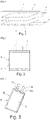
- FIG. 3 illustrates this type of flexible packaging 6 which is arranged to insulate and seal the electrochemical cell C while being crossed by a part of two strips or tongues 4, 5, commonly called in English "tab", forming the terminals or poles and which extend in the plane of the electrochemical cell.
- the tab 4, constituting the positive terminal is in the form of a metal strip with a thickness of 0.2 to 0.4 mm, usually aluminum.
- the tongue 5, constituting the negative terminal is in the form of a metal strip of 0.2 to 0.4 mm, most often made of nickel material or copper or nickel-plated copper.
- the main advantage of flexible packaging is their lightness.
- the Li-ion accumulators with the highest energy densities therefore have a flexible packaging.
- Soft-packaged batteries are increasingly used due to their high energy density.
- a flexible accumulator commonly called in English “ Thin Film Battery”, is most often made up of a single electrochemical cell.
- the total thickness of the accumulator with its flexible packaging is generally less than 16 mm, which is a function of the dimensions and the chemistry of the electrode materials, and this without altering the performance during operation of the accumulator.
- a battery pack consists of a variable number of accumulators which can reach several thousand which are electrically connected in series or in parallel with each other and generally by connection bars, usually called busbars.
- a battery module or a battery pack with flexible accumulators is an assembly by stacking a plurality of these flexible accumulators of prismatic geometry.
- the term "accumulator of prismatic geometry” means an accumulator of globally prismatic shape, that is to say of globally parallelepipedic shape, flattened along one dimension, independently of its embodiment which may be by rolling up a cell, by stacking, etc.
- a difficulty inherent in an assembly by stacking flexible accumulators is to be able to ensure reliable electrical connections between the electrode terminals (tabs or “tabs”) of the various stacked accumulators without increasing the weight or the complexity of the assembly too much. in himself.
- accumulators stacked on top of each other are electrically connected by electrode tabs ("tabs") which are connected to each other using wires, plates or busbars by welding.
- a common method consists in performing laser welds on a copper or aluminum current collector of the “busbar” type.
- FIG 4 shows an embodiment of a battery module produced with such a process: the flexible accumulators A1 to A10 are stacked against each other and electrode tabs (“tabs”) 4 are each welded by a laser weld bead S to a plate forming a busbar 7.1 to 7.3.
- the tongues 4 are partially bent, and the plates forming the busbars 7.1 to 7.3 are connected to the bent parts, which can be complex to achieve.
- connected parts may separate from each other due to external impacts, which may lead to an increase in the number of defective products.
- this assembly by welding eliminates any possibility of replacing a defective accumulator with another within the stack or else at an unreasonable cost. In other words, it prohibits any non-destructive dismantling once completed.
- connection "tabs" of small or even very small thickness.
- the patent EP2854200B1 describes an integration of a single flexible accumulator inside a rigid casing then, once the integration has been completed, the electrical connection of the "tabs" to the power connectors of a bar which forms a terminal block.
- the object of the invention is to meet this need at least in part.
- the guide extends obliquely with respect to the longitudinal axis and the holding element extends obliquely or perpendicularly to the longitudinal axis, the holding element being even more preferably perpendicular to the longitudinal axis.
- the guide preferably extends obliquely with respect to the notch with an angle of inclination comprised between 20° and 70°.
- the longitudinal axis preferably comprises a major component along the axis of the stack of accumulators.
- the body can be one-piece or alternatively comprise a plurality of unit blocks assembled together by a dovetail connection, each of the unit blocks incorporating a notch, a guide and a clamping pin mounted sliding in the guide.
- the body is electrically conductive, preferably made of copper or aluminum.
- the body comprises at least one of its longitudinal ends a lug for electrical connection to an element outside the module or pack, preferably provided with an electrical connection eyelet.
- the invention essentially consists in defining, as an electrical connection component between accumulators with tongues forming the poles or terminals, a busbar into the body of which each tongue is inserted then gripped in a vice by a clamping pin forming a movable jaw which can be easily moved by sliding in the body so as to make an electrical connection in series or in parallel depending on the need.
- the sliding of the clamping pin to its clamping position is ensured by a pressure screw, screwed into the body of the busbar and which bears against a reference and support surface to achieve the desired clamping and the mechanical support of the pawn.
- the diameter of the contact surface with an electrode tab, which determines the current passage section, can be easily adapted according to the specifications of a module or battery pack.
- a guide of the clamping pin is made inclined with respect to the longitudinal axis of the body. Because of this inclination, if traditional machining does not allow the desired body to be produced, then machining by electroerosion or high pressure molding can be envisaged.
- the body can also be easily produced using additive manufacturing technologies (3D printing) such as powder sintering (FLS).
- a busbar according to the invention to a chosen number of accumulators within a battery module or battery pack, instead of a one-piece body, a plurality of blocks can be assembled together. connection with a fast mechanical system allowing mechanical and electrical assembly of the blocks relative to each other.
- the accumulators A1 to AN illustrated are of prismatic format, with flexible packaging 6, usually called "pouch".
- the accumulators A1 to AN can be electrically connected in series and/or in parallel in a module or in a battery pack by means of at least one busbar according to the invention.
- FIG 5 an example of part of a battery module M comprising several adjacent accumulators A1, A2, ... A6, that is to say stacked on top of each other, the electrode tongues of which (“tabs”) 4 are all electrically interconnected by means of an electrical connection busbar 8 according to the invention, which is removably fixed to each of these tabs 4 as detailed below.
- the electrical connection busbar 8 firstly comprises a body 9 elongated along a longitudinal axis (X1) and in which a plurality of notches 90, a plurality of housings 91 each forming a guide opening onto an edge of one of the notches 90.
- a clamping pin 10 comprising at one of its longitudinal ends a contact surface 100 is slidably mounted in each guide 91 between an initial position in which its contact surface 100 is set back from a notch 90 ( figure 8 ) and a clamping position in which its contact surface 100 flattens and clamps the electrode tab 4 inserted in the notch against the edge of the latter which is opposite to that on which the guide opens ( figure 5 ).
- the notch 90 extends orthogonally to the longitudinal axis X1 and the guide 91 extends obliquely relative to the longitudinal axis X1 and the contact surface 100 is a bevel extending also orthogonal to the X1 axis.
- the angle formed between the axis of the guide 91 and the plane of the notch is equal to 34°.
- An element 11 detachably holds the clamping pin 10 in its clamping position.
- the holding element is a clamping screw 11 which is screwed into a threaded housing 92.
- This clamping screw 11 for example with a hexagonal head, makes it possible both to move the pin 10 so that it presses against and clamps a tongue 4 against the edge of the notch 90 and to guarantee its mechanical maintenance in its tightening position.
- the pin 10 forms a sort of clamping jaw.
- the pin 10 has a notch in its central portion to define a reference and bearing surface 101 on which the clamping screw 11 exerts its pressure.
- a screwing force on the screw 11 makes it possible to move the pin 10 in its housing 11 then to block it when it reaches its clamping position of the tongue 4.
- the pin 11 can be made according to needs (dimensioning and contact pressure) in metal, typically in aluminum or in a material having better mechanical strength such as stainless steel.
- the diameter of the pin 11 and its angle of tangency (inclination of the housing 91) determine the contact surface 100, therefore the current flow section through the tongue 4 tightened.
- the contact surface 100 can be approximately 50mm 2 for a current of between 350 and 500A.
- the body 9 of the busbar 8 is in one piece.
- the body 9 consists of the assembly of several unit blocks 9.1, 9.2, 9.3 assembled together by dovetail systems 96.
- each unitary block 9.1 comprises, on one of its longitudinal edges, a tenon 97 of one of the dovetail connections and on the other of its longitudinal edges, opposite the tenon, a groove 98 of another dovetail linkages.
- a tenon 97 fits into a groove 98 of complementary shape to that of the tenon 97 to ensure assembly between two adjacent unit blocks.
- the tenon 97 and the groove 98 have a cross section which is trapezoidal.
- each clamping pin 10 is moved from its initial position to its clamping position by a clamping screw 11.
- FIG. 11 And 12 show an alternative according to which all the clamping pins 10 are moved simultaneously and with a uniform force by means of a compression plate 12 which can be moved in translation by means of a clamping screw 13, which is screwed to the body 9 busbar preferably in its central portion.
- the compression plate 12 bears directly against the longitudinal end 102 of all the clamping pins 10, this end 102 thus constituting a reference and bearing surface for the plate 12.
- the surface 102 is hemispherical.
- guide pins 14 forming slides can be inserted in the body 9 and in the through holes of the plate 12.
- FIG 11 shows an arrangement in which the compression plate 12 can be arranged completely inside the body 9 with a portion 99 thereof covering it.
- figure 12 shows an arrangement where the plate 12 is arranged directly on top of the body 9, which presents with respect to the arrangement of the figure 11 of greater compactness.
- busbar 8 With a busbar 8 according to the invention as described, several integrations can easily be carried out in battery modules M with different arrangements.
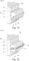
- the busbar 8 can be fixed on an upper longitudinal edge 40 of the tabs 4 ( figure 13 ) or on the lower edge 41 ( figure 14 ) or even on the end side edge 42 ( figure 14 ).
- the flexible packaging of the accumulators in accordance with the invention are of prismatic format, the invention of course applies to all flexible packaging accumulators which comprise, as terminals or poles, tongues or "tabs".
- the body 9 of the busbar 8 is electrically conductive, for example made of aluminum or copper.
- the electric current passes through the body 9 and it is possible to provide for this purpose that the body 9 has at one and/or the other of its longitudinal ends an electrical connection lug 93 in particular provided with a electrical connection eyelet 94.
- the body 9 is electrically insulating.
- the electric current can pass through the clamping pins 10 and/or the holding means, in particular the compression plate 12 which are electrically conductive, as for the examples of figure 11 And 12 .
- a clamping screw 11 and a compression plate 12 instead of a clamping screw 11 and a compression plate 12, other mechanical holding elements for a clamping pin 10 can be envisaged, which can moreover serve only for holding and not also to the movement of said pawn.
- a cam locking system of the type found in toggle clamps, an indexing finger that would block the pin or even a calibrated spring system...
- the same busbar according to the invention is fixed and connects a plurality of electrode tongues of the same polarity. It goes without saying that depending on the desired electrical configurations (electrical series or parallel), it is possible to envisage having the same busbar fixing and electrically connecting tongues of positive and negative polarity.
- a single block incorporates a single notch and a single clamping pin. It is also possible to envisage making blocks assembled with others, of different dimensions and/or comprising several notches and clamping pins.
- the assembly system between blocks shown is a dovetail system.
- Other assembly methods can be envisaged, for example tenon-mortise with screw or pin.
- the cross section of the tenon and of the groove can be triangular instead of being trapezoidal.
Landscapes
- Chemical & Material Sciences (AREA)
- Chemical Kinetics & Catalysis (AREA)
- Electrochemistry (AREA)
- General Chemical & Material Sciences (AREA)
- Battery Mounting, Suspending (AREA)
Applications Claiming Priority (1)
| Application Number | Priority Date | Filing Date | Title |
|---|---|---|---|
| FR2110004A FR3127334B1 (fr) | 2021-09-23 | 2021-09-23 | Busbar pour module de batterie ou pack-batterie à empilement d’accumulateurs à emballage souple, destinée à connecter électriquement au moins un accumulateur du module ou pack, Procédé de réalisation d’un module ou pack-batterie associé. |
Publications (1)
| Publication Number | Publication Date |
|---|---|
| EP4156391A1 true EP4156391A1 (de) | 2023-03-29 |
Family
ID=78086592
Family Applications (1)
| Application Number | Title | Priority Date | Filing Date |
|---|---|---|---|
| EP22197211.0A Pending EP4156391A1 (de) | 2021-09-23 | 2022-09-22 | Busbar für ein batteriemodul oder ein stapelbatteriepack für flexible batterien zur elektrischen verbindung mindestens eines akkumulators des moduls oder pakets, verfahren zur herstellung eines batteriemoduls oder eines batteriepacks |
Country Status (2)
| Country | Link |
|---|---|
| EP (1) | EP4156391A1 (de) |
| FR (1) | FR3127334B1 (de) |
Cited By (2)
| Publication number | Priority date | Publication date | Assignee | Title |
|---|---|---|---|---|
| FR3156250A1 (fr) * | 2023-12-04 | 2025-06-06 | Commissariat A L'energie Atomique Et Aux Energies Alternatives | Dispositif de raccordement électrique d'une cellule d'accumulateur à borne souple |
| WO2025125514A1 (fr) * | 2023-12-14 | 2025-06-19 | Ampere S.A.S. | Batterie d'accumulateurs electrique |
Citations (11)
| Publication number | Priority date | Publication date | Assignee | Title |
|---|---|---|---|---|
| US20060121348A1 (en) | 2004-11-09 | 2006-06-08 | Satoshi Mizutani | Anode active material and battery |
| US7335448B2 (en) | 2002-05-30 | 2008-02-26 | Matsushita Electric Industrial Co., Ltd. | Lithium ion secondary battery |
| US7338733B2 (en) | 2002-04-30 | 2008-03-04 | Sanyo Electric Co., Ltd. | Battery pack |
| US20080057392A1 (en) | 2006-08-31 | 2008-03-06 | Nissan Motor Co., Ltd. | Battery module |
| US20080060189A1 (en) | 2006-09-08 | 2008-03-13 | Nec Tokin Corporation | Method for production of stacked battery |
| US7348098B2 (en) | 2000-10-13 | 2008-03-25 | Matsushita Electric Industrial Co., Ltd. | Flat prismatic battery |
| KR20120136542A (ko) | 2011-06-09 | 2012-12-20 | 인셀(주) | 파우치형 이차전지의 단자 연결 구조 |
| US8361647B2 (en) * | 2010-03-19 | 2013-01-29 | GM Global Technology Operations LLC | Reversible battery assembly and tooling for automated high volume production |
| WO2014126341A1 (ko) | 2013-02-14 | 2014-08-21 | 에스케이이노베이션 주식회사 | 배터리 셀 전극탭 연결장치 및 이를 포함하는 배터리 모듈 |
| EP2854200B1 (de) | 2012-07-23 | 2017-01-11 | Lg Chem, Ltd. | Rechteckige batteriezelle mit integrierter beutelförmiger batteriezelle |
| US20180013124A1 (en) * | 2016-07-05 | 2018-01-11 | Ammon N. Balaster | Modular Power Storage and Supply System |
-
2021
- 2021-09-23 FR FR2110004A patent/FR3127334B1/fr active Active
-
2022
- 2022-09-22 EP EP22197211.0A patent/EP4156391A1/de active Pending
Patent Citations (11)
| Publication number | Priority date | Publication date | Assignee | Title |
|---|---|---|---|---|
| US7348098B2 (en) | 2000-10-13 | 2008-03-25 | Matsushita Electric Industrial Co., Ltd. | Flat prismatic battery |
| US7338733B2 (en) | 2002-04-30 | 2008-03-04 | Sanyo Electric Co., Ltd. | Battery pack |
| US7335448B2 (en) | 2002-05-30 | 2008-02-26 | Matsushita Electric Industrial Co., Ltd. | Lithium ion secondary battery |
| US20060121348A1 (en) | 2004-11-09 | 2006-06-08 | Satoshi Mizutani | Anode active material and battery |
| US20080057392A1 (en) | 2006-08-31 | 2008-03-06 | Nissan Motor Co., Ltd. | Battery module |
| US20080060189A1 (en) | 2006-09-08 | 2008-03-13 | Nec Tokin Corporation | Method for production of stacked battery |
| US8361647B2 (en) * | 2010-03-19 | 2013-01-29 | GM Global Technology Operations LLC | Reversible battery assembly and tooling for automated high volume production |
| KR20120136542A (ko) | 2011-06-09 | 2012-12-20 | 인셀(주) | 파우치형 이차전지의 단자 연결 구조 |
| EP2854200B1 (de) | 2012-07-23 | 2017-01-11 | Lg Chem, Ltd. | Rechteckige batteriezelle mit integrierter beutelförmiger batteriezelle |
| WO2014126341A1 (ko) | 2013-02-14 | 2014-08-21 | 에스케이이노베이션 주식회사 | 배터리 셀 전극탭 연결장치 및 이를 포함하는 배터리 모듈 |
| US20180013124A1 (en) * | 2016-07-05 | 2018-01-11 | Ammon N. Balaster | Modular Power Storage and Supply System |
Cited By (4)
| Publication number | Priority date | Publication date | Assignee | Title |
|---|---|---|---|---|
| FR3156250A1 (fr) * | 2023-12-04 | 2025-06-06 | Commissariat A L'energie Atomique Et Aux Energies Alternatives | Dispositif de raccordement électrique d'une cellule d'accumulateur à borne souple |
| EP4567999A1 (de) * | 2023-12-04 | 2025-06-11 | Commissariat à l'Energie Atomique et aux Energies Alternatives | Elektrische anschlussvorrichtung für eine speicherzelle mit flexiblem anschluss |
| WO2025125514A1 (fr) * | 2023-12-14 | 2025-06-19 | Ampere S.A.S. | Batterie d'accumulateurs electrique |
| FR3157013A1 (fr) * | 2023-12-14 | 2025-06-20 | Ampere Sas | Batterie d’accumulateurs electrique |
Also Published As
| Publication number | Publication date |
|---|---|
| FR3127334A1 (fr) | 2023-03-24 |
| FR3127334B1 (fr) | 2024-03-01 |
Similar Documents
| Publication | Publication Date | Title |
|---|---|---|
| EP2842185B1 (de) | Buchse zur formung eines anschlusses für eine lithiumspeicherbatterie und zugehörige speicherbatterie | |
| EP2870655B1 (de) | Stromabnehmer mit integrierter dichtungsvorrichtung, bipolare batterie mit solch einem stromabnehmer | |
| EP3985769B1 (de) | Batteriemodul mit stapel von weich verpackten akkumulatoren, die in festen halterungen zwischen ihnen durch knappen oder klippen und stützklemmen in druckkontakt mit den akkumulatorklemmen gehäuset werden. | |
| EP3179532B1 (de) | Dichter querträger vom typ glas-metall, seine verwendung für elektrochemischen lithiumakkumulator und entsprechendes herstellungsverfahren | |
| FR3011128A1 (fr) | Procede de realisation d'un faisceau electrochimique d'un accumulateur au lithium | |
| FR3068831A1 (fr) | Procedes de realisation d'un faisceau electrochimique d'un accumulateur metal-ion au moyen d'une membrane a electrolyte polymere gelifie, accumulateurs associes | |
| FR3127334A1 (fr) | Busbar pour module de batterie ou pack-batterie à empilement d’accumulateurs à emballage souple, destinée à connecter électriquement au moins un accumulateur du module ou pack, Procédé de réalisation d’un module ou pack-batterie associé. | |
| EP3095147B1 (de) | Elektrochemischer akkumulator mit gehäuse und terminal bestehend aus einer aluminiumlegierung | |
| EP3472880A1 (de) | Elektrode für ein elektrochemisches bündel einer metall-ionen-speicherbatterie oder eines superkondensators, verfahren zur herstellung des zugehörigen bündels und speicherbatterie | |
| EP3327818B1 (de) | Metallionen batterie mit einem elektrodenstapel aufweisend hohe kapazität und hohe leistung | |
| EP4199220A2 (de) | Batteriemodul oder batteriepack mit flexiblen verbindungen mit komplementären sperrformen als kompressionsmittel, verfahren zur herstellung eines moduls oder batteriepacks | |
| EP4187695B1 (de) | Batteriemodul mit in gestapelten trägern übereinander angeordneten und miteinander verbundenen stromschienen mit an den anschluss angeschlossenen batterieanschlüssen angeordneten stapelpaketen. | |
| EP4187696B1 (de) | Batteriemodul mit einem stapel aus flexiblen verpackungen, die in durch formschlüssige verbindung miteinander verbunden sind, und die unterstützung von ineinander verschachtelten busbarnen | |
| EP4383418B1 (de) | Batteriemodul mit einem stapel aus flexiblen verpackungen, die in trägern mit formschlüssiger verbindung stehen, die busbar mit stromunterbrechungsleitungen (dci) unterstützen | |
| FR3059159A1 (fr) | Electrode pour faisceau electrochimique d'un accumulateur metal-ion a forte densite d'energie, accumulateur cylindrique ou prismatique associe | |
| EP3510652B1 (de) | Durchführung zur bildung einer klemme für eine elektrochemische metall-ionen-batterie und entsprechende batterie | |
| FR3143214A1 (fr) | Module de batterie ou pack-batterie, comprenant une matrice à accumulateurs de format cylindrique, logée et bridée dans un boitier périphérique. | |
| EP4187703A2 (de) | Batteriemodul oder batteriepack mit gehäuse mit flexiblen verbindungen mit komplementären sperrformen als mechanische haltevorrichtung für das gehäuse, verfahren zur herstellung eines batteriemoduls oder eines batteriepacks | |
| EP3327819B1 (de) | Metallionen-akkumulator mit einem stapel elektroden, gekennzeichnet durch eine hohe energiedichte und eine hohe kapazität | |
| FR3156596A1 (fr) | Module de batterie ou pack-batterie, comprenant une matrice à accumulateurs de format cylindrique articulés entre eux par bielle(s) à axe(s) d’articulation formé(s) par les boitiers des accumulateurs. | |
| FR3156597A1 (fr) | Module de batterie ou pack-batterie, comprenant une matrice à accumulateurs de format cylindrique articulés entre eux par bielle(s) à axe(s) d’articulation formé(s) par les boitiers des accumulateurs et à busbars réalisant des connexions électriques dans certaines positions articulées. | |
| FR2894718A1 (fr) | Module de batterie | |
| FR3016736A1 (fr) | Batterie lithium-ion (li-ion) a capacite augmentee par augmentation de la hauteur disponible a l'interieur du boitier |
Legal Events
| Date | Code | Title | Description |
|---|---|---|---|
| PUAI | Public reference made under article 153(3) epc to a published international application that has entered the european phase |
Free format text: ORIGINAL CODE: 0009012 |
|
| STAA | Information on the status of an ep patent application or granted ep patent |
Free format text: STATUS: REQUEST FOR EXAMINATION WAS MADE |
|
| 17P | Request for examination filed |
Effective date: 20220922 |
|
| AK | Designated contracting states |
Kind code of ref document: A1 Designated state(s): AL AT BE BG CH CY CZ DE DK EE ES FI FR GB GR HR HU IE IS IT LI LT LU LV MC MK MT NL NO PL PT RO RS SE SI SK SM TR |
|
| STAA | Information on the status of an ep patent application or granted ep patent |
Free format text: STATUS: EXAMINATION IS IN PROGRESS |
|
| 17Q | First examination report despatched |
Effective date: 20230823 |
|
| RAP3 | Party data changed (applicant data changed or rights of an application transferred) |
Owner name: COMMISSARIAT A L'ENERGIE ATOMIQUE ET AUX ENERGIESALTERNATIVES |