EP4156472A1 - Magnetische dichtung für magnetempfindliche vorrichtungen, systeme und verfahren - Google Patents
Magnetische dichtung für magnetempfindliche vorrichtungen, systeme und verfahren Download PDFInfo
- Publication number
- EP4156472A1 EP4156472A1 EP22204944.7A EP22204944A EP4156472A1 EP 4156472 A1 EP4156472 A1 EP 4156472A1 EP 22204944 A EP22204944 A EP 22204944A EP 4156472 A1 EP4156472 A1 EP 4156472A1
- Authority
- EP
- European Patent Office
- Prior art keywords
- magnetic
- magnetically
- seal
- responsive
- concentrator
- Prior art date
- Legal status (The legal status is an assumption and is not a legal conclusion. Google has not performed a legal analysis and makes no representation as to the accuracy of the status listed.)
- Pending
Links
- 238000000034 method Methods 0.000 title claims abstract description 18
- 230000004907 flux Effects 0.000 claims abstract description 41
- 239000000843 powder Substances 0.000 claims abstract description 28
- 230000004888 barrier function Effects 0.000 claims abstract description 21
- 125000006850 spacer group Chemical group 0.000 claims abstract description 18
- 239000012141 concentrate Substances 0.000 claims abstract description 9
- 239000000463 material Substances 0.000 claims description 12
- 239000000696 magnetic material Substances 0.000 claims description 8
- 230000008878 coupling Effects 0.000 claims description 6
- 238000010168 coupling process Methods 0.000 claims description 6
- 238000005859 coupling reaction Methods 0.000 claims description 6
- 239000011800 void material Substances 0.000 description 14
- 238000007789 sealing Methods 0.000 description 8
- 238000013461 design Methods 0.000 description 6
- 238000009825 accumulation Methods 0.000 description 4
- 238000011109 contamination Methods 0.000 description 4
- 229910001220 stainless steel Inorganic materials 0.000 description 4
- 239000010935 stainless steel Substances 0.000 description 4
- 229910000755 6061-T6 aluminium alloy Inorganic materials 0.000 description 3
- 229910001209 Low-carbon steel Inorganic materials 0.000 description 3
- 230000005012 migration Effects 0.000 description 3
- 238000013508 migration Methods 0.000 description 3
- XEEYBQQBJWHFJM-UHFFFAOYSA-N Iron Chemical compound [Fe] XEEYBQQBJWHFJM-UHFFFAOYSA-N 0.000 description 2
- 230000008859 change Effects 0.000 description 2
- 230000007246 mechanism Effects 0.000 description 2
- QEFYFXOXNSNQGX-UHFFFAOYSA-N neodymium atom Chemical group [Nd] QEFYFXOXNSNQGX-UHFFFAOYSA-N 0.000 description 2
- 229910000838 Al alloy Inorganic materials 0.000 description 1
- 239000004677 Nylon Substances 0.000 description 1
- 101150013568 US16 gene Proteins 0.000 description 1
- 229910052782 aluminium Inorganic materials 0.000 description 1
- XAGFODPZIPBFFR-UHFFFAOYSA-N aluminium Chemical compound [Al] XAGFODPZIPBFFR-UHFFFAOYSA-N 0.000 description 1
- 238000011161 development Methods 0.000 description 1
- 238000005516 engineering process Methods 0.000 description 1
- 230000002452 interceptive effect Effects 0.000 description 1
- 229920001778 nylon Polymers 0.000 description 1
- 239000002245 particle Substances 0.000 description 1
- 230000036316 preload Effects 0.000 description 1
- 230000009467 reduction Effects 0.000 description 1
- 229920006395 saturated elastomer Polymers 0.000 description 1
- 238000006467 substitution reaction Methods 0.000 description 1
- 238000012360 testing method Methods 0.000 description 1
Images




Classifications
-
- H—ELECTRICITY
- H02—GENERATION; CONVERSION OR DISTRIBUTION OF ELECTRIC POWER
- H02K—DYNAMO-ELECTRIC MACHINES
- H02K5/00—Casings; Enclosures; Supports
- H02K5/04—Casings or enclosures characterised by the shape, form or construction thereof
- H02K5/12—Casings or enclosures characterised by the shape, form or construction thereof specially adapted for operating in liquid or gas
- H02K5/124—Sealing of shafts
-
- F—MECHANICAL ENGINEERING; LIGHTING; HEATING; WEAPONS; BLASTING
- F16—ENGINEERING ELEMENTS AND UNITS; GENERAL MEASURES FOR PRODUCING AND MAINTAINING EFFECTIVE FUNCTIONING OF MACHINES OR INSTALLATIONS; THERMAL INSULATION IN GENERAL
- F16D—COUPLINGS FOR TRANSMITTING ROTATION; CLUTCHES; BRAKES
- F16D57/00—Liquid-resistance brakes; Brakes using the internal friction of fluids or fluid-like media, e.g. powders
- F16D57/002—Liquid-resistance brakes; Brakes using the internal friction of fluids or fluid-like media, e.g. powders comprising a medium with electrically or magnetically controlled internal friction, e.g. electrorheological fluid, magnetic powder
-
- H—ELECTRICITY
- H02—GENERATION; CONVERSION OR DISTRIBUTION OF ELECTRIC POWER
- H02K—DYNAMO-ELECTRIC MACHINES
- H02K1/00—Details of the magnetic circuit
- H02K1/06—Details of the magnetic circuit characterised by the shape, form or construction
- H02K1/22—Rotating parts of the magnetic circuit
- H02K1/24—Rotor cores with salient poles ; Variable reluctance rotors
- H02K1/246—Variable reluctance rotors
-
- H—ELECTRICITY
- H02—GENERATION; CONVERSION OR DISTRIBUTION OF ELECTRIC POWER
- H02K—DYNAMO-ELECTRIC MACHINES
- H02K5/00—Casings; Enclosures; Supports
- H02K5/04—Casings or enclosures characterised by the shape, form or construction thereof
- H02K5/16—Means for supporting bearings, e.g. insulating supports or means for fitting bearings in the bearing-shields
- H02K5/161—Means for supporting bearings, e.g. insulating supports or means for fitting bearings in the bearing-shields radially supporting the rotary shaft at both ends of the rotor
-
- H—ELECTRICITY
- H02—GENERATION; CONVERSION OR DISTRIBUTION OF ELECTRIC POWER
- H02K—DYNAMO-ELECTRIC MACHINES
- H02K7/00—Arrangements for handling mechanical energy structurally associated with dynamo-electric machines, e.g. structural association with mechanical driving motors or auxiliary dynamo-electric machines
- H02K7/08—Structural association with bearings
- H02K7/083—Structural association with bearings radially supporting the rotary shaft at both ends of the rotor
-
- F—MECHANICAL ENGINEERING; LIGHTING; HEATING; WEAPONS; BLASTING
- F16—ENGINEERING ELEMENTS AND UNITS; GENERAL MEASURES FOR PRODUCING AND MAINTAINING EFFECTIVE FUNCTIONING OF MACHINES OR INSTALLATIONS; THERMAL INSULATION IN GENERAL
- F16D—COUPLINGS FOR TRANSMITTING ROTATION; CLUTCHES; BRAKES
- F16D2121/00—Type of actuator operation force
- F16D2121/18—Electric or magnetic
- F16D2121/20—Electric or magnetic using electromagnets
Definitions
- the subject matter disclosed herein relates generally to magnetically-responsive systems. More particularly, the subject matter disclosed herein relates to seals for use with magnetically-responsive systems to prevent the migration of magnetically-responsive material out of the systems.
- tactile feedback devices in steer-by-wire systems in which torque feedback to the operator is generated when a rotor attached to a shaft shears MR material against a fixed stator.
- tactile feedback device steering units can utilize a fine magnetically responsive (MR) material (iron powder) to provide smooth torque, proportional to current and independent of temperature.
- MR magnetically responsive
- the typical functionality of a tactile feedback device includes torque feedback, position (rotational) sensing, and structure.
- bearings or bushings are generally used to support the output shaft.
- Traditional bearings and bushings are susceptible, however, to binding in failure when contaminated by MR powders.
- the bearing When powder enters the bearing, the bearing has a tendency to seize or provide "stiff steering" at the operator interface. This failure mode has driven the development of special seals that are designed to mitigate leak paths that contribute to contamination.
- current solutions include compressed felt, labyrinth seals, radial lip seals, and axial lip seals.
- a magnetically-responsive device contained within a housing.
- the device comprises a shaft, a rotor, a magnetic field generators, a magnetically-responsive medium, and a magnetic seal.
- the rotor comprised of a highly magnetically permeable material, the rotor being interconnected to the shaft to restrain relative rotation therebetween.
- the magnetic field generator separated from the rotor by a void, the magnetic field generator having an electromagnet stator.
- the magnetically-responsive medium contained within and at least partially filling the void wherein the magnetic field generator is controllable to cause the magnetically-responsive medium to align along the flux path within the void and thereby cause a change in torsional resistance of the rotor.
- the magnetic seal positioned proximate the shaft, the magnetic seal comprising a magnetic element configured to generate a magnetic field to prevent passage of the magnetically-responsive medium out of the void.
- a magnetically-responsive device comprises a magnetic seal that is configured to be positioned at or near a rotatable shaft.
- the magnetic seal includes a magnetic element configured to generate a magnetic field to prevent passage of magnetically-responsive medium along a rotatable shaft.
- a method for preventing passage of a magnetically-responsive medium out of a magnetically-responsive device comprises the steps of positioning a magnetic seal at or near a rotating shaft associated with the magnetic-resistive device and generating a magnetic field to prevent passage of the magnetically-responsive medium along the shaft away from the magnetically-responsive device.
- the present subject matter provides magnetic seals for magnetically-responsive devices, systems, and methods.
- the present subject matter provides magnetic seals that are designed to prevent contamination of bearings or bushings by concentrating the magnetic flux in an area that will prevent passage of the magnetically responsive materials.
- typical sealing methods include axial/radial elastomeric contact seals, and these types of seals do not do well with dry contamination and break down over time.
- non-contacting magnetic seals can retain powder and prevent leakage even with a gap present between the fixed and moving components.
- a magnetically-responsive device generally designated 100 includes a shaft 110 and a rotor 130 interconnected to shaft 110 to restrain relative rotation therebetween.
- rotor 130 includes a highly-magnetically-permeable material (e.g., a mid/low carbon steel such as AISI-1018).
- a housing 140 is positioned substantially about shaft 110 and rotor 130 .
- one or more pole 142 is attached to or integrated within housing 140 , and a magnetic field generator 145 associated with pole 142 is spaced from rotor 130 by a void 150 .
- magnetic field generator 145 is a fixed stator (e.g., a permanent magnet and/or an electromagnetic coil) that is configured to generate a magnetic field in at least a portion of pole 142 at or near rotor 130 .
- a magnetically responsive medium e.g., a magnetically-responsive powder such as iron powder
- magnetic field generator 145 is controllable to cause the magnetically-responsive medium to align along the flux path within void 150 and thereby cause a change in torsional resistance of rotor 130 (and shaft 110 ).
- bearings or bushings are generally used to support the output shaft. In the configuration shown in Figure 1 , bearings 121, 122 are positioned on either side of rotor 130 along shaft 110 .
- a better mechanism for sealing the magnetically responsive medium is provided. As will be discussed in further detail below, a magnetic seal provides such a mechanism.
- a magnetic seal 160 is spaced from rotor 130 (i.e., between bearing 121 and rotor 130 ) and positioned at or near shaft 110
- a magnetic seal 170 is likewise spaced from rotor 130 (i.e., between bearing 122 and rotor 130 ) and positioned at or near shaft 110 .
- the spacings between bearing 121 and magnetic seal 160 and between bearing 122 and magnetic seal 170 are designed so that the races of bearings 121, 122 do not become magnetized, which can result in the bearings attracting the magnetically-responsive medium.
- Each of magnetic seal 160 and magnetic seal 170 includes a magnetic element configured to generate a magnetic field to restrict and/or prevent passage of the magnetically-responsive medium out of void 150 and along shaft 110 towards bearings 121, 122 .
- the magnetic seal 160, 170 is separated from the shaft 110 by a gap 161, 171 that prevents contact between the shaft 110 and an internal diameter of the magnetic seal 160, 170 .
- the magnetic element is a ring magnet (e.g., a Neodymium ring magnet with standard polarity).
- a ring magnet 172 is positioned between housing 140 and shaft 110 .
- ring magnet 172 is coupled to housing 140 by a magnet holder 174 , which is composed of a non-magnetic material (e.g., 6061-T6 Aluminum or similar).
- ring magnet 172 can provide its magnetic sealing function without interfering with the operation of magnetic field generator 145 as shown in Figure 2B .
- reference is made to an exemplary configuration for magnetic seal 170 those having skill in the art should recognize that the concepts disclosed herein can be similarly applied to the configuration of magnetic seal 160 .
- a ring magnet In addition to being able to provide a powder barrier 173 to limit or prevent the passage of the magnetically-responsive medium towards bearing 122 , the use of a ring magnet can do without contacting shaft 110 .
- a small first gap 161 exists between magnetic seal 160 and shaft 110
- a second gap 171 exists between magnetic seal 170 and shaft 110 .
- the size of second gap 171 is larger than the molecular/particle size of the magnetically-responsive medium (e.g., approximately 100 micrometers or less), but as discussed above, the seal is designed to impede movement of the magnetically-responsive medium without requiring a physical barrier against shaft 110 .
- the absence of contact resulting from even such a small gap results in a reduction in the torsional resistance imparted on shaft 110 compared to traditional seals that generally require a pre-load with no gap.
- the magnetic seals according to the present subject matter do so without deleteriously affecting the operation of the associated magnetically-responsive systems.
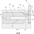
- magnetic seal 170 is configured such that the magnetic field generated is concentrated above the magnet. This concentration of the field is achieved by coupling a magnetic flux core 176 with ring magnet 172 to concentrate the flux to align magnetically-responsive medium in area serving as powder barrier 173 .
- a non-magnetic spacer 178 e.g., a nylon ring
- This non-magnetic spacer 178 is configured to radially expand the flux "crown" that is generated in the space between magnetic seal 170 and the rotating elements (i.e., shaft 110 and rotor 130 ).
- FIG. 4A and 4B An exemplary configuration for magnetic seal 170 in this configuration is illustrated in Figures 4A and 4B .
- ring magnet 172 is nested substantially concentrically within a concentrator element 175 , which includes flux core 176 .
- flux core 176 is configured to shape the magnetic field generated by ring magnet 172 to have a desired path as discussed above.
- concentrator element 175 further includes spacer 178 , which is configured to be positioned between ring magnet 172 and flux core 176 to prevent shorting.
- ring magnet 172 In the embodiments shown in Figures 4A and 4B , ring magnet 172 , flux core 176 , and spacer 178 are all nested within magnet holder 174 , which is configured for attachment to a fixed element of the system (e.g., to housing 140 ).
- magnetic seal 170 is configured such that it is configured to rotate with shaft 110 rather than being attached to a fixed element of the system.
- magnetic seal 170 is spaced from rotor 130 (i.e., between bearing 121 and rotor 130 ).
- the spacing between bearing 121 and magnetic seal 170 are designed so that the races of bearing 121 do not become magnetized, which can result in the bearings attracting the magnetically-responsive medium.
- magnetic seal 170 includes a magnetic element configured to generate a magnetic field to restrict and/or prevent passage of the magnetically-responsive medium out of void 150 (e.g., into gap 161 ) and along shaft 110 (e.g., towards bearing 121 ).
- a secondary lower seal 190 e.g., a compressed felt or elastomeric element is also positioned between rotor 130 and bearing 122 .
- magnetic seal 170 is attached to rotor 130 (e.g., centered about shaft 110 ) and is separated from housing 140 by a gap.
- the magnetic element is a ring magnet 172 (e.g., a Neodymium ring magnet with standard polarity).
- one or more magnetic concentrator elements e.g., one or more non-magnetic spacer 178 ) are configured to concentrate magnetic flux to align the magnetically-responsive medium in the area serving as powder barrier 173 .
- a pair of non-magnetic spacers 178 is positioned on opposing sides (i.e., one on a first side and one on a second side) of ring magnet 172 and function as magnetic concentrator elements.
- FIGs 5B and 5C which illustrate the magnetic flux generated by embodiments of magnetic seal 170 , this configuration concentrates the magnetic flux axially and away from the central axis.
- shaft 110 is composed of a non-magnetic material (e.g., 316SS or 304SS stainless steel, aluminum, or aluminum alloys), and thus the magnetic flux generated by the magnetic seal and the size and position of powder barrier 173 is largely controlled by the configuration of ring magnet 172 and non-magnetic spacer 178 .
- Figure 5C illustrates an embodiment in which shaft 110 is composed of a magnetically-responsive medium (e.g., a mid/low carbon steel such as AISI-1018 or AISI-4140).
- shaft 110 and/or rotor 130 effectively serves as a flux core for magnetic seal 170 and closes the magnetic flux loop, and thus the expansion of this circuit helps to concentrate the flux to align the magnetically-responsive medium in the area serving as powder barrier 173 .
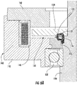
- ring magnet 172 is positioned between housing 140 and rotor 130 to provide powder barrier 173 to limit or prevent the passage of the magnetically-responsive medium towards bearing 121 .
- a separate magnetic flux core 176 is coupled with ring magnet 172 for rotation with rotor 130 to concentrate the flux to align magnetically-responsive medium in the area serving as powder barrier 173 .
- the magnetic flux generated by the magnetic seal e.g., combination of ring magnet 172 and flux core 176
- the magnetic flux generated by the magnetic seal is controlled in the region between shaft 110 and the fixed elements to create powder barrier 173 as shown in Figure 6B .
- a further barrier element 115 that is composed of a non-magnetic material (e.g., 6061-T6 Aluminum or similar) is coupled with housing 140 below magnetic seal 170 and is configured to impede accumulation of the magnetically-responsive medium at or near magnetic seal 170 .
- barrier elements 115 is affixed to, integrated with, or otherwise coupled to housing 140 .
- the magnetic flux is concentrated axially and away from the central axis, which in some situations can lead to an accumulation of powder that collects around magnetic seals 160 and 170 .
- a non-magnetic element is provided in void 150 such that only a small gap (e.g., about 1 mm) remains between magnetic seals 160 and 170 and rotor 130 .
- shaft 110 is itself shaped to have a diameter that varies along its length.
- the diameter of shaft 110 is comparatively narrow in the region of second gap 171 , but shaft 110 widens in the area above magnetic seal 170 to extend into void 150 .
- this "step out" in the diameter of shaft 110 functions as a non-magnetic barrier to provide only a small gap above magnetic seal 170 to trap the accumulation of powder.
- barrier element 115 that is composed of a non-magnetic material (e.g., 6061-T6 Aluminum or similar) is coupled with shaft 110 above magnetic seal 170 .
- barrier element 115 has an outer diameter that is substantially similar to a diameter of flux core 176 so that substantially the entire crown of powder that is formed is contained between these elements.
- a magnetic seal such as those discussed above provides a non-contact seal that does not deteriorate over time.
- Typical sealing methods include axial/radial elastomeric contact seals. These types of seals do not do well with dry contamination, they break down over time, and they generally require contact with the rotating shaft, which imparts undesirable torsional resistance.
- the non-contacting magnetic seals retain powder and prevent leakage even with a gap present between the fixed and moving components. As a result, this solution is able to replace traditional seal features entirely.
- a magnetic seal of this kind is part of a combination sealing system that includes both magnetic elements and conventional sealing features.
- magnetic seal 170 is positioned near an end of void 150 between rotor 130 and pole 142 , but a secondary lower seal 190 is also positioned between rotor 130 and bearing 122.
- secondary lower seal 190 includes a compressed felt or elastomeric element that forms a contact seal against shaft 110 .
- shaft 110 be composed of non-magnetically-responsive medium (e.g., 316SS or 304SS stainless steel) and/or that a non-magnetic barrier element 115 be positioned between the magnetic seals and the rotating elements so that the operation of magnetic seals 160 and 170 do not confound the ability of rotor 130 and magnetic field generator 145 to control the amount of torsional resistance of rotor 130 (and shaft 110 ).
- non-magnetically-responsive medium e.g., 316SS or 304SS stainless steel
- shaft 110 is composed of a magnetically-responsive medium (e.g., a mid/low carbon steel such as AISI-1018 or AISI-4140)
- a magnetically-responsive medium e.g., a mid/low carbon steel such as AISI-1018 or AISI-4140
- operation of magnetic seals 160 and 170 also generates a torque on shaft 110 .
- This torque is a function of the magnetic flux path, passing through the powder medium and returning through the magnetic shaft. The flux generated in this way aligns the magnetically responsive medium, generating a shear force.
- MR brake configurations include a rotor, pole, and coil embedded in a housing
- magnets to generate torque between the stator, rotor, and magnetically responsive medium.
- This substitution provides a reliable design, but it also includes multiple components to provide both torque and structural rigidity (e.g., shaft, rotor, stator, coil, two bearings, housing, magnetically responsive powder or other medium, seals, cover, wire harness).
- magnetic seals 160 and 170 are able to function as a magnetic brake that could be dramatically simplified.
- the minimum part count for a ring magnet brake merely includes a shaft, magnet, bearings, pole, housing, and the magnetically responsive power or other material.
- such a design can be potentially limited in torque capability as a result of the limited diameter. That being said, application of the presently disclosed subject matter provides a low cost fixed resistance brake in some situations.
Landscapes
- Engineering & Computer Science (AREA)
- Power Engineering (AREA)
- General Engineering & Computer Science (AREA)
- Mechanical Engineering (AREA)
- Sealing Using Fluids, Sealing Without Contact, And Removal Of Oil (AREA)
Applications Claiming Priority (3)
| Application Number | Priority Date | Filing Date | Title |
|---|---|---|---|
| PCT/US2016/048137 WO2018038708A1 (en) | 2016-08-23 | 2016-08-23 | Magnetic seal for magnetically-responsive devices, systems, and methods |
| EP17758417.4A EP3504776B1 (de) | 2016-08-23 | 2017-08-23 | Magnetische dichtung für eine magnetisch gesteuerte vorrichtung, system und verfahren |
| PCT/US2017/048132 WO2018039301A1 (en) | 2016-08-23 | 2017-08-23 | Magnetic seal for magnetically-responsive devices, systems, and methods |
Related Parent Applications (1)
| Application Number | Title | Priority Date | Filing Date |
|---|---|---|---|
| EP17758417.4A Division EP3504776B1 (de) | 2016-08-23 | 2017-08-23 | Magnetische dichtung für eine magnetisch gesteuerte vorrichtung, system und verfahren |
Publications (1)
| Publication Number | Publication Date |
|---|---|
| EP4156472A1 true EP4156472A1 (de) | 2023-03-29 |
Family
ID=56990947
Family Applications (3)
| Application Number | Title | Priority Date | Filing Date |
|---|---|---|---|
| EP16770586.2A Withdrawn EP3504775A1 (de) | 2016-08-23 | 2016-08-23 | Magnetdichtung für magnetisch reagierende vorrichtungen, systeme und verfahren |
| EP22204944.7A Pending EP4156472A1 (de) | 2016-08-23 | 2017-08-23 | Magnetische dichtung für magnetempfindliche vorrichtungen, systeme und verfahren |
| EP17758417.4A Active EP3504776B1 (de) | 2016-08-23 | 2017-08-23 | Magnetische dichtung für eine magnetisch gesteuerte vorrichtung, system und verfahren |
Family Applications Before (1)
| Application Number | Title | Priority Date | Filing Date |
|---|---|---|---|
| EP16770586.2A Withdrawn EP3504775A1 (de) | 2016-08-23 | 2016-08-23 | Magnetdichtung für magnetisch reagierende vorrichtungen, systeme und verfahren |
Family Applications After (1)
| Application Number | Title | Priority Date | Filing Date |
|---|---|---|---|
| EP17758417.4A Active EP3504776B1 (de) | 2016-08-23 | 2017-08-23 | Magnetische dichtung für eine magnetisch gesteuerte vorrichtung, system und verfahren |
Country Status (4)
| Country | Link |
|---|---|
| US (2) | US11095184B2 (de) |
| EP (3) | EP3504775A1 (de) |
| CN (2) | CN109643930A (de) |
| WO (2) | WO2018038708A1 (de) |
Families Citing this family (7)
| Publication number | Priority date | Publication date | Assignee | Title |
|---|---|---|---|---|
| CN109643930A (zh) | 2016-08-23 | 2019-04-16 | 洛德公司 | 用于磁响应装置、系统和方法的磁性密封件 |
| DE102019135760A1 (de) * | 2019-12-18 | 2021-06-24 | Inventus Engineering Gmbh | Magnetorheologische Bremseinrichtung |
| EP4081760B1 (de) | 2019-12-26 | 2025-05-07 | LORD Corporation | Sensoranordnung mit doppelmagnet |
| CN112483548A (zh) * | 2020-12-14 | 2021-03-12 | 唐汉东 | 铁粉内环式不锈钢磁密封轴承 |
| DE102021111965A1 (de) | 2021-05-06 | 2022-11-10 | Inventus Engineering Gmbh | Magnetorheologische Bremsvorrichtung, insbesondere Bedieneinrichtung |
| DE102021111973A1 (de) | 2021-05-06 | 2022-11-10 | Inventus Engineering Gmbh | Magnetorheologische Bremsvorrichtung, insbesondere Bedieneinrichtung |
| US12529218B2 (en) * | 2023-06-09 | 2026-01-20 | Brian Zimmerman | Levitated drain stopper |
Citations (5)
| Publication number | Priority date | Publication date | Assignee | Title |
|---|---|---|---|---|
| US5173814A (en) * | 1981-09-07 | 1992-12-22 | Papst-Motoren Gmbh & Co. Kg | Disk storage drive having internal electrical connection passages and contamination seals at ends of the motor |
| GB2273395A (en) * | 1992-12-11 | 1994-06-15 | Hitachi Ltd | A motor with a bearing lubricated by magnetic fluid |
| WO2000045498A2 (en) * | 1999-01-29 | 2000-08-03 | Seagate Technology Llc | Particle free shield assembly for spindle motor |
| EP1677022A1 (de) * | 2004-12-28 | 2006-07-05 | Hitachi Koki Co., Ltd. | Dreh-Impuls-Generator und hiermit versehenes angetriebenes Werkzeug |
| WO2015113564A1 (de) * | 2014-02-03 | 2015-08-06 | Schaeffler Technologies AG & Co. KG | Magnetorheologischer aktor mit rotatorisch angetriebener gewindespindel und kupplung mit aktor |
Family Cites Families (37)
| Publication number | Priority date | Publication date | Assignee | Title |
|---|---|---|---|---|
| US2824460A (en) | 1954-11-24 | 1958-02-25 | Foxboro Co | Magnetic reversible nut |
| US3254745A (en) | 1963-01-21 | 1966-06-07 | Isakov Vladimir Olimpijevich | Seal to protect the bearings of powder magnetic clutches or of similar devices against the ferromagnetic powder |
| US3788275A (en) | 1972-06-28 | 1974-01-29 | Xerox Corp | Magnetic shielding apparatus |
| US4239092A (en) | 1978-08-28 | 1980-12-16 | Dana Corporation | Adjustable tensioner |
| US4575103A (en) | 1984-04-09 | 1986-03-11 | Pedu Alexander A | Magnetic seal for magnetic particle clutches and brakes |
| US4681197A (en) | 1984-09-19 | 1987-07-21 | Placid Industries, Inc. | Electromagnetic clutches and brakes |
| US4844220A (en) | 1986-02-26 | 1989-07-04 | Shinko Electric Co., Ltd. | Torque limiter |
| JPS6418636U (de) | 1987-07-24 | 1989-01-30 | ||
| NL8902086A (nl) | 1989-08-17 | 1991-03-18 | Skf Ind Trading & Dev | Afdicht- en glijlagersamenstel met een magnetische vloeistof. |
| US5816372A (en) | 1994-09-09 | 1998-10-06 | Lord Corporation | Magnetorheological fluid devices and process of controlling force in exercise equipment utilizing same |
| JPH0979263A (ja) | 1995-09-20 | 1997-03-25 | Hitachi Ltd | 軸受装置及びこれを備えたスピンドルモ−タ |
| JP3768571B2 (ja) | 1995-10-06 | 2006-04-19 | 日本電産株式会社 | スピンドルモータ |
| US5969589A (en) | 1996-08-28 | 1999-10-19 | Ferrofluidics Corporation | Quiet ferrofluid solenoid |
| US6466119B1 (en) | 1996-09-06 | 2002-10-15 | Chester Drew | Magnetic circuit |
| US6029978A (en) * | 1996-09-17 | 2000-02-29 | Seagate Technology, Inc. | Grounding and conductivity improvement for ferrofluid seals |
| JP2000088004A (ja) | 1998-09-11 | 2000-03-28 | Shinko Electric Co Ltd | 磁性流体シール付きパウダブレーキ・クラッチ |
| DE10044106C2 (de) | 1999-09-30 | 2002-02-28 | Prec Motors Deutsche Minebea G | Spindelmotor mit Magnetfluiddichtung |
| JP4705714B2 (ja) | 2000-10-20 | 2011-06-22 | オリエンタルモーター株式会社 | 簡易負荷装置 |
| JP2003013955A (ja) | 2001-07-02 | 2003-01-15 | Ishikawajima Harima Heavy Ind Co Ltd | 磁気軸受用ステータコア |
| CN1520496A (zh) | 2001-12-31 | 2004-08-11 | 罗产尼瑞科有限公司 | 使用磁粉的刹车设备 |
| US6725990B2 (en) | 2002-02-19 | 2004-04-27 | New Venture Gear, Inc. | Torque transfer clutch with magnetorheological actuator and ball screw operator |
| US7113365B1 (en) | 2002-12-24 | 2006-09-26 | Western Digital Technologies, Inc. | Disk drive comprising a spindle motor having a windings shield for reduced disk voltage coupling |
| US6755290B1 (en) | 2003-02-03 | 2004-06-29 | New Venture Gear, Inc. | Power transmission device for a four-wheel drive vehicle |
| DE10333733A1 (de) | 2003-07-23 | 2005-02-24 | Forschungszentrum Jülich GmbH | Magnetisches Lagerelement |
| US6942081B2 (en) | 2003-11-03 | 2005-09-13 | China Patent Investment Limited | Electrorheological clutch |
| EP1881300B3 (de) | 2005-05-10 | 2021-12-15 | NSK Ltd. | Magnetcodierer und wälzlagereinheit mit dem magnetcodierer |
| US7208854B1 (en) * | 2006-03-09 | 2007-04-24 | Hamilton Sundstrand Corporation | Rotor cooling system for synchronous machines with conductive sleeve |
| DE102006037992A1 (de) | 2006-08-14 | 2008-02-21 | Magna Powertrain Ag & Co Kg | Bauteil mit Haltefunktion, Aufhaltesystem und Verfahren zu deren Betrieb |
| WO2008059788A1 (en) | 2006-11-16 | 2008-05-22 | Jtekt Corporation | Sensor-equipped sealing device, and rolling bearing device adapted for use in vehicle and using the sealing device |
| US20080116757A1 (en) | 2006-11-17 | 2008-05-22 | Sean Chang | Motor having magnetic fluid bearing structure |
| US8215467B2 (en) | 2008-10-21 | 2012-07-10 | GM Global Technology Operations LLC | Multi-gap magnetorheological fluid clutch |
| CN102349218B (zh) | 2009-03-11 | 2014-01-29 | 香港中文大学 | 多功能磁流变驱动机构 |
| DE102010064067A1 (de) | 2010-12-23 | 2012-06-28 | Siemens Aktiengesellschaft | Radialmagnetlager zur magnetischen Lagerung eines Rotors |
| CN103051151B (zh) | 2012-12-12 | 2015-09-09 | 海安县兰菱机电设备有限公司 | 立式磁粉制动器 |
| US9453386B2 (en) | 2013-12-31 | 2016-09-27 | Cameron International Corporation | Magnetorheological fluid locking system |
| CN104242597A (zh) | 2014-09-23 | 2014-12-24 | 东莞市科特机电有限公司 | 制动器磁性粉末密封结构 |
| CN109643930A (zh) | 2016-08-23 | 2019-04-16 | 洛德公司 | 用于磁响应装置、系统和方法的磁性密封件 |
-
2016
- 2016-08-23 CN CN201680088659.4A patent/CN109643930A/zh active Pending
- 2016-08-23 EP EP16770586.2A patent/EP3504775A1/de not_active Withdrawn
- 2016-08-23 US US16/322,003 patent/US11095184B2/en active Active
- 2016-08-23 WO PCT/US2016/048137 patent/WO2018038708A1/en not_active Ceased
-
2017
- 2017-08-23 EP EP22204944.7A patent/EP4156472A1/de active Pending
- 2017-08-23 CN CN201780051867.1A patent/CN109690917A/zh active Pending
- 2017-08-23 EP EP17758417.4A patent/EP3504776B1/de active Active
- 2017-08-23 US US16/321,926 patent/US11081928B2/en active Active
- 2017-08-23 WO PCT/US2017/048132 patent/WO2018039301A1/en not_active Ceased
Patent Citations (5)
| Publication number | Priority date | Publication date | Assignee | Title |
|---|---|---|---|---|
| US5173814A (en) * | 1981-09-07 | 1992-12-22 | Papst-Motoren Gmbh & Co. Kg | Disk storage drive having internal electrical connection passages and contamination seals at ends of the motor |
| GB2273395A (en) * | 1992-12-11 | 1994-06-15 | Hitachi Ltd | A motor with a bearing lubricated by magnetic fluid |
| WO2000045498A2 (en) * | 1999-01-29 | 2000-08-03 | Seagate Technology Llc | Particle free shield assembly for spindle motor |
| EP1677022A1 (de) * | 2004-12-28 | 2006-07-05 | Hitachi Koki Co., Ltd. | Dreh-Impuls-Generator und hiermit versehenes angetriebenes Werkzeug |
| WO2015113564A1 (de) * | 2014-02-03 | 2015-08-06 | Schaeffler Technologies AG & Co. KG | Magnetorheologischer aktor mit rotatorisch angetriebener gewindespindel und kupplung mit aktor |
Also Published As
| Publication number | Publication date |
|---|---|
| WO2018039301A1 (en) | 2018-03-01 |
| US20190178316A1 (en) | 2019-06-13 |
| WO2018038708A1 (en) | 2018-03-01 |
| EP3504775A1 (de) | 2019-07-03 |
| US20190181716A1 (en) | 2019-06-13 |
| CN109643930A (zh) | 2019-04-16 |
| CN109690917A (zh) | 2019-04-26 |
| US11095184B2 (en) | 2021-08-17 |
| US11081928B2 (en) | 2021-08-03 |
| EP3504776A1 (de) | 2019-07-03 |
| EP3504776B1 (de) | 2022-11-02 |
Similar Documents
| Publication | Publication Date | Title |
|---|---|---|
| US11081928B2 (en) | Magnetic seal for magnetically-responsive devices, systems, and methods | |
| US8378543B2 (en) | Generating electromagnetic forces in large air gaps | |
| JP4496376B2 (ja) | 使い捨て磁気浮上式血液ポンプ | |
| EP2528202A2 (de) | Elektromagnetischer Aktuator | |
| JP6193856B2 (ja) | アクチュエータとアクチュエータのヨーク内に埋め込まれたセンサとを備えた小型位置決めアセンブリ | |
| KR101527313B1 (ko) | 회전 이음매 | |
| CN106300851A (zh) | 气隙控制系统和方法 | |
| JP6464407B2 (ja) | 磁性流体シールの組立方法及び磁性流体シール | |
| CN102792039A (zh) | 磁性轴承和涡轮机 | |
| CN106165271A (zh) | 包括两个独立移动构件的线性电磁致动器 | |
| US6770995B1 (en) | Passive radial magnetic bearing | |
| US8963393B2 (en) | Magnetic thrust bearings | |
| JP2009106690A (ja) | 磁気浮上式血液ポンプ | |
| CN106895075B (zh) | 一种双偏转隐式洛伦兹力偏转磁轴承 | |
| JP5527765B2 (ja) | 磁気粘性流体を用いた回転制動装置 | |
| JP5527766B2 (ja) | 磁気粘性流体を用いた回転制動装置 | |
| GB2297361A (en) | Active magnetic bearing system | |
| JP2019054593A (ja) | 異物の侵入を抑制する電動機 | |
| EP0414294A1 (de) | Dichtung und Lager mit magnetisierbarer Flüssigkeit | |
| KR101438403B1 (ko) | 자기 베어링 장치 및 그 제어방법 | |
| JP2008286285A (ja) | 電磁クラッチ | |
| JP5947946B2 (ja) | 無励磁作動型電磁ブレーキ | |
| RU131104U1 (ru) | Гибридный магнитный подшипник | |
| KR101287057B1 (ko) | 자기베어링이 구비된 터보기기 | |
| RU64725U1 (ru) | Магнитожидкостное уплотнение |
Legal Events
| Date | Code | Title | Description |
|---|---|---|---|
| PUAI | Public reference made under article 153(3) epc to a published international application that has entered the european phase |
Free format text: ORIGINAL CODE: 0009012 |
|
| STAA | Information on the status of an ep patent application or granted ep patent |
Free format text: STATUS: THE APPLICATION HAS BEEN PUBLISHED |
|
| AC | Divisional application: reference to earlier application |
Ref document number: 3504776 Country of ref document: EP Kind code of ref document: P |
|
| AK | Designated contracting states |
Kind code of ref document: A1 Designated state(s): AL AT BE BG CH CY CZ DE DK EE ES FI FR GB GR HR HU IE IS IT LI LT LU LV MC MK MT NL NO PL PT RO RS SE SI SK SM TR |
|
| P01 | Opt-out of the competence of the unified patent court (upc) registered |
Effective date: 20230524 |
|
| STAA | Information on the status of an ep patent application or granted ep patent |
Free format text: STATUS: REQUEST FOR EXAMINATION WAS MADE |
|
| 17P | Request for examination filed |
Effective date: 20230926 |
|
| RBV | Designated contracting states (corrected) |
Designated state(s): AL AT BE BG CH CY CZ DE DK EE ES FI FR GB GR HR HU IE IS IT LI LT LU LV MC MK MT NL NO PL PT RO RS SE SI SK SM TR |
|
| RAP3 | Party data changed (applicant data changed or rights of an application transferred) |
Owner name: LORD CORPORATION |