EP4157548B1 - Tête de distribution à grille pour un distributeur compact - Google Patents
Tête de distribution à grille pour un distributeur compact Download PDFInfo
- Publication number
- EP4157548B1 EP4157548B1 EP21737142.6A EP21737142A EP4157548B1 EP 4157548 B1 EP4157548 B1 EP 4157548B1 EP 21737142 A EP21737142 A EP 21737142A EP 4157548 B1 EP4157548 B1 EP 4157548B1
- Authority
- EP
- European Patent Office
- Prior art keywords
- dispensing
- dispensing head
- piston chamber
- piston
- head according
- Prior art date
- Legal status (The legal status is an assumption and is not a legal conclusion. Google has not performed a legal analysis and makes no representation as to the accuracy of the status listed.)
- Active
Links
Images





Classifications
-
- B—PERFORMING OPERATIONS; TRANSPORTING
- B05—SPRAYING OR ATOMISING IN GENERAL; APPLYING FLUENT MATERIALS TO SURFACES, IN GENERAL
- B05B—SPRAYING APPARATUS; ATOMISING APPARATUS; NOZZLES
- B05B11/00—Single-unit hand-held apparatus in which flow of contents is produced by the muscular force of the operator at the moment of use
- B05B11/01—Single-unit hand-held apparatus in which flow of contents is produced by the muscular force of the operator at the moment of use characterised by the means producing the flow
- B05B11/10—Pump arrangements for transferring the contents from the container to a pump chamber by a sucking effect and forcing the contents out through the dispensing nozzle
- B05B11/1038—Pressure accumulation pumps, i.e. pumps comprising a pressure accumulation chamber
- B05B11/1039—Pressure accumulation pumps, i.e. pumps comprising a pressure accumulation chamber the outlet valve being mechanically opened after a defined accumulation stroke
-
- B—PERFORMING OPERATIONS; TRANSPORTING
- B05—SPRAYING OR ATOMISING IN GENERAL; APPLYING FLUENT MATERIALS TO SURFACES, IN GENERAL
- B05B—SPRAYING APPARATUS; ATOMISING APPARATUS; NOZZLES
- B05B11/00—Single-unit hand-held apparatus in which flow of contents is produced by the muscular force of the operator at the moment of use
- B05B11/01—Single-unit hand-held apparatus in which flow of contents is produced by the muscular force of the operator at the moment of use characterised by the means producing the flow
- B05B11/10—Pump arrangements for transferring the contents from the container to a pump chamber by a sucking effect and forcing the contents out through the dispensing nozzle
- B05B11/1001—Piston pumps
- B05B11/1009—Piston pumps actuated by a lever
- B05B11/1011—Piston pumps actuated by a lever without substantial movement of the nozzle in the direction of the pressure stroke
-
- B—PERFORMING OPERATIONS; TRANSPORTING
- B05—SPRAYING OR ATOMISING IN GENERAL; APPLYING FLUENT MATERIALS TO SURFACES, IN GENERAL
- B05B—SPRAYING APPARATUS; ATOMISING APPARATUS; NOZZLES
- B05B11/00—Single-unit hand-held apparatus in which flow of contents is produced by the muscular force of the operator at the moment of use
- B05B11/01—Single-unit hand-held apparatus in which flow of contents is produced by the muscular force of the operator at the moment of use characterised by the means producing the flow
- B05B11/10—Pump arrangements for transferring the contents from the container to a pump chamber by a sucking effect and forcing the contents out through the dispensing nozzle
- B05B11/1042—Components or details
- B05B11/1073—Springs
- B05B11/1074—Springs located outside pump chambers
-
- B—PERFORMING OPERATIONS; TRANSPORTING
- B05—SPRAYING OR ATOMISING IN GENERAL; APPLYING FLUENT MATERIALS TO SURFACES, IN GENERAL
- B05B—SPRAYING APPARATUS; ATOMISING APPARATUS; NOZZLES
- B05B11/00—Single-unit hand-held apparatus in which flow of contents is produced by the muscular force of the operator at the moment of use
- B05B11/01—Single-unit hand-held apparatus in which flow of contents is produced by the muscular force of the operator at the moment of use characterised by the means producing the flow
- B05B11/10—Pump arrangements for transferring the contents from the container to a pump chamber by a sucking effect and forcing the contents out through the dispensing nozzle
- B05B11/1042—Components or details
- B05B11/1073—Springs
- B05B11/1077—Springs characterised by a particular shape or material
-
- B—PERFORMING OPERATIONS; TRANSPORTING
- B05—SPRAYING OR ATOMISING IN GENERAL; APPLYING FLUENT MATERIALS TO SURFACES, IN GENERAL
- B05B—SPRAYING APPARATUS; ATOMISING APPARATUS; NOZZLES
- B05B11/00—Single-unit hand-held apparatus in which flow of contents is produced by the muscular force of the operator at the moment of use
- B05B11/0005—Components or details
- B05B11/0008—Sealing or attachment arrangements between sprayer and container
-
- B—PERFORMING OPERATIONS; TRANSPORTING
- B05—SPRAYING OR ATOMISING IN GENERAL; APPLYING FLUENT MATERIALS TO SURFACES, IN GENERAL
- B05B—SPRAYING APPARATUS; ATOMISING APPARATUS; NOZZLES
- B05B11/00—Single-unit hand-held apparatus in which flow of contents is produced by the muscular force of the operator at the moment of use
- B05B11/0005—Components or details
- B05B11/0062—Outlet valves actuated by the pressure of the fluid to be sprayed
- B05B11/007—Outlet valves actuated by the pressure of the fluid to be sprayed being opened by deformation of a sealing element made of resiliently deformable material, e.g. flaps, skirts, duck-bill valves
Definitions
- This patent application relates to the sector of trigger dispensers used for dispensing liquid products, in innumerable applications.
- a trigger dispensing head for compact dispensers usually named "mini-triggers”.
- These trigger dispensers are usually used in the personal care sector, e.g., for dispensing sun care products, or for air care products, characterized by very small dimensions compared to the dispensers usually used in other applications, such as that of household hygiene. Indeed, in some sectors, such as those mentioned, it is necessary to be able to dispense small doses of the product, given its nature, or have small-size bottles because they contain seasonal products.
- the manufacturing of the operating spring on the trigger has proven to be particularly difficult because it is easily subject to yielding due to the new materials to be used and the small dimensions compared to those of the dispensing heads used in other sectors.
- the yielding of the spring results in a malfunctioning of the dispensing head because the trigger does not return to the resting position and neither does the piston connected to it so that the piston chamber does not fill adequately and the desired dose of the product is not dispensed.
- Examples of trigger dispensing heads with ineffective control of their elastic return elements are disclosed in documents WO2017/115159A1 , WO2019/116115A1 and WO2011/128787A1 .
- reference numeral 1 indicates a trigger dispensing device, e.g., for containing liquid personal care products, e.g., for dispensing sun care or air care products.
- the dispensing device 1 comprises a bottle 2 for containing the product to be dispensed, provided with a neck 4 having a central neck axis Z, and a dispensing head 6 with trigger 8 for manual actuation, applied to the neck 4 of the bottle 2, e.g. by means of a bayonet or threaded connection ( figure 1 ).
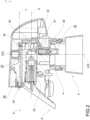
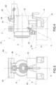
- the dispensing head 6 comprises a frame 10 for supporting the other components of the head, typically made in one piece of plastic material, preferably chosen from the group of polyolefins, e.g., by injection molding ( figures 2 to 4 ) .
- the frame 10 comprises a connecting portion 12 for the preferably releasable connection to the neck 4 of the bottle 2.
- the connecting portion 12 comprises an annular skirt 12a coaxial to the neck 4, thus having a skirt axis J coincident with the neck axis Z, provided with a plurality of windows 14 and fins 16, e.g., flexible, for connecting by snapping with elements provided on the neck, and a base 12b closing the skirt 12a on top, the skirt preferably lying on a base plane P orthogonal to the neck axis Z.
- the frame 10 further comprises a first annular wall 18 which delimits a piston chamber 20 which extends along a piston axis X incident to the skirt axis J, e.g., orthogonally thereto.
- the head 6 further comprises a piston 22, operatively connected to the trigger 8, sealably sliding in the piston chamber 20 with reciprocating motion, to aspirate the liquid product from the bottle into the piston chamber in a step of suction and to dispense liquid product from the piston chamber to the outside in a step of dispensing.
- the piston 22 and the piston chamber 20 are an example of pumping means adapted to be actuated by the trigger 8 to aspirate the liquid product from the bottle in a step of suction and to dispense the liquid product outside in a step of dispensing.
- the frame 10 further comprises a second annular wall 24 which delimits a dispensing pipe 26 which extends along a dispensing axis Y incident to the skirt axis J, e.g., orthogonally thereto.
- the dispensing axis Y is parallel to and spaced apart from the piston axis X and preferably on the side opposite to the connecting portion 12 relative to the piston axis X.
- a sagittal plane S is defined for the head 10, e.g., a symmetry plane, containing the piston axis X and the dispensing axis Y, and preferably passing through the skirt axis J; the sagittal plane S subdivides the head 10 into a right half-part R and a left half-part L, with reference to the dispensing direction of the product, which occurs frontally.
- the head 10 further comprises a nozzle 28 applied to the free end of the dispensing pipe 26, e.g., to form the jet of the product during dispensing.
- the head 6 further comprises an inlet pipe 30 adapted to put the compartment inside the bottle 2 in communication with the piston chamber 20; the inlet pipe 30 extends from an inlet port 32 for the ingress of the aspirated product and an outlet port 34 for the ingress of the product into the piston chamber 20.
- said inlet pipe is formed in the frame 10.
- the head 6 comprises non-return valve means, operating along the inlet pipe 30, adapted to allow the transit of the liquid product from the bottle to the piston chamber 20 in the step of suction and to prevent the return of the product from the piston chamber 20 to the bottle in the step of product dispensing.
- said non-return valve means comprise a ball 36 which in the step of dispensing closes the inlet port 32 of the inlet pipe 30, and in the step of suction clears said inlet port 32.
- the head 6 further comprises an outlet pipe 38 adapted to put the piston chamber 20 into communication with the dispensing pipe 26.
- the head 6 comprises dispensing valve means, operating along the outlet pipe 38, adapted to allow the transit of the liquid product from the piston chamber 20 towards the outlet pipe 38 in a step of dispensing and to prevent the ingress of air from outside the piston chamber 20 in the step of product suction.
- said valve dispensing means comprise a deformable membrane 40.
- a portion of the membrane 40 cooperates with the frame 10 to partially delimit the outlet pipe 38.
- said dispensing valve means are precompression means, adapted to allow the transit of the product from the piston chamber 20 to the dispensing pipe 26 only when the pressure of the product in the piston chamber 20 exceeds a predefined threshold value.
- said valve delivery means are of the mechanically triggered type, i.e., they are mechanically forced to go from the closing configuration to the opening configuration.
- said dispensing valve means are biased by the piston 22 at a trigger position in which it mechanically interferes with the dispensing valve means to forcibly transit from the closing configuration to the opening configuration.
- the piston 22 is provided with a protrusion 22a which, in the triggered position, mechanically operates on the membrane 40 to make it pass into the opening configuration.
- the head 6 comprises a lower backing part 50 supported by the frame 10.
- the lower backing part 50 is part of the frame 10 and, preferably, is located between the base 12b of the connecting portion 12 and the first wall 28 of the piston chamber 20.
- the lower backing part 50 extends from the right half-part R to the left half-part L, preferably continuously.
- the lower backing part 50 has a flat main surface 52 lying on a backing part plane A incident to the base plane P; e.g., the backing part plane A forms with the base plane P on the front, i.e., on the product dispensing side, an acute ( ⁇ 90°) backing angle C, e.g., an angle greater than 60°, preferably between 65 and 85°, preferably equal to 75°.
- an acute ( ⁇ 90°) backing angle C e.g., an angle greater than 60°, preferably between 65 and 85°, preferably equal to 75°.
- the frame 10 comprises a plurality of ribs 54, e.g., parallel to the base plane P, which join the lower backing part 50 to the remaining portion of the frame 10.
- the head 6 comprises an upper backing part 60 supported by the frame 10.
- the upper backing part 60 is part of the frame 10 and, preferably, overlies the dispensing pipe 26, i.e., it is located above the dispensing axis Y relative to the piston axis X, and extends from the second wall 24 into the right half-part R and the left half-part L, preferably continuously.
- the upper backing part 60 has a seat 62 having an arched bottom seat surface 64; a step 66 is placed preferably at the ingress of the seat 62 to achieve a coupling by snapping of the component inserted into the seat 62.
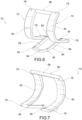
- the head 6 comprises an at least partially elastic return element 70 ( figures 6 to 10 ), preferably made in one piece, preferably of plastic material, preferably chosen from the family of polyolefins or post-consumer recycled (PCR) or post-industrial recycled (PIR) materials, typically by injection molding.
- plastic material preferably chosen from the family of polyolefins or post-consumer recycled (PCR) or post-industrial recycled (PIR) materials, typically by injection molding.
- the return element 70 comprises a pair of elastically deformable arms 72, 74; each arm 72, 74 extends from a lower end 76 to an upper end 78. Furthermore, each arm 72, 74 is arched and has a convex, forward-facing front face 80 and a concave, rear-facing rear face 82.
- the return element 70 further comprises a lower joining portion 84, which joins the lower ends 76 of the two arms 72, 74.
- the lower joining portion 84 comprises a pair of preferably straight branches 86, 88; each branch 86, 88 has a rear end 90 joined to a respective lower end 76 of the arm 72, 74, and a front end 92.
- the front ends 92 of the two branches 86, 88 are joined together by a lower crosspiece 94, preferably arched and in particular concave above and convex below.
- the return element 70 further comprises an upper joining portion 96, which joins the upper ends 78 of the two arms 72, 74.
- the upper joining portion 96 comprises an upper crosspiece 98, preferably having a rounded outer surface.
- each arm 72, 74 is arranged in a respective semi-part R, L of the head 6; in other words, the piston chamber 20 is arranged between said arms 72, 74.
- the front faces 80 are forward-facing and the rear faces 82 backward-facing.
- the upper joining portion 96 backs the upper backing part 60, and in particular is accommodated in the seat 62, preferably engaged by snapping with said upper backing part 60.
- the lower ends 76 of the two arms 72, 74 are freely movable on the main surface 52 in receding and approaching relative to the upper ends 78 between a plurality of zones of said main surface 52 spaced along the skirt axis J of the skirt 12b.
- the lower joining portion 84 is instead arranged under the piston chamber 20, and in particular between the piston chamber 20 and the connecting portion 12 of the frame 10.
- the end actuating zone F3 is under the intermediate actuating zone F2 and the intermediate actuating zone F2 is under the resting zone F1 (consequently, the end actuating zone F3 is under the resting zone F1).
- the resting zone F1 is positioned above and distanced from the intermediate actuating zone F2. Furthermore, the intermediate actuating zone F2 is positioned above and distanced from the end actuating zone F3.
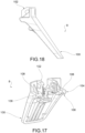
- the trigger 8 ( figures 17 and 18 ) comprises a gripping portion 100 for the user's fingers, an engagement portion 102, e.g., located at the end of the gripping portion 100, for engaging with the frame 10, and an actuating portion 104 for operating on the return element 70.
- the actuating portion 104 comprises two noses 106, each one intended to operate on one of the arms 72, 74 of the return element 70.
- each nose 106 protrudes behind from the gripping portion 100 and ends with a contact surface 108 shaped to make a cam in contact with the arms 72, 74 of the return element 70, to optimize the course of the resistance action applied by the return element, perceived by the user's fingers.
- the trigger 8 is hinged to the frame 10, preferably through the engagement portion 102 hinged to a pin protruding from the second wall 24 of the dispensing pipe 26.
- the trigger 8 is preloaded by the return element 70 so that the noses 106 are permanently in contact with the front faces 80 of the arms 72, 74 of the return element 70.
- the pumping means comprise a piston chamber delimited by a deformable elastic membrane.
- the dispensing pipe is delimited by a flexible tube connecting the piston chamber to the nozzle.
- the non-return valve means comprise a flexible membrane valve.
- the dispensing valve means comprise a spring-piston assembly.
- the backing part angle is a right angle.
- the trigger is translatable relative to the frame between a resting configuration and an actuating configuration or is roto-translatable.
- the non-return element operates directly on the piston, returning it from the actuating position to the resting position; the piston, in turn, operates on the trigger.
- the trigger dispensing device makes it possible to limit incipient stresses in the return element, so that the return element does not experience yielding, even after repeated cycles of use, while still providing the necessary return action to the trigger.
- the conformation of the lower backing part and the movable lower ends on the main surface make it possible to limit the entity of the stresses arising in the return element at every step of use of the device, thus avoiding yielding.
- the conformation of the upper backing part and the upper ends rotatable therein make it possible to limit the entity of the biases arising in the return element in every step of use of the device, thus avoiding yielding.
- the conformation of the trigger noses allows the action on the trigger and the return element to be optimized.
Landscapes
- Containers And Packaging Bodies Having A Special Means To Remove Contents (AREA)
- Closures For Containers (AREA)
- Portable Nailing Machines And Staplers (AREA)
- Coating Apparatus (AREA)
Claims (14)
- Tête de distribution à gâchette (6) pour distribuer un produit liquide, qui peut être appliquée à une bouteille (2) d'un dispositif de distribution (1), comprenant :- un cadre (10) pour supporter des composantes de la tête de distribution (6), comprenant une partie de raccordement (12) pour une application à la bouteille (2), comprenant une jupe annulaire (12b) comportant un axe de jupe (1) ;- une chambre de piston (20) supportée par le cadre (10), présentant une extension le long d'un axe de piston (X), et un piston (22) coulissant hermétiquement dans la chambre de piston (20), entre une position de repos et une position de distribution dans laquelle le produit est distribué à l'extérieur ;- un tuyau de distribution (26) supporté par le cadre (10), en communication fluidique avec la chambre de piston (20), pour distribuer, à l'avant, le produit, présentant une extension le long d'un axe de distribution (Y), dans laquelle l'axe de piston (X) et l'axe de distribution (Y) se trouvent dans un plan sagittal (S) imaginaire ; dans laquelle le plan sagittal (S) subdivise la tête (10) en une demi-partie droite et une demi-partie gauche ;une gâchette (8) supportée par le cadre (10), qui peut être actionnée pour solliciter le piston (22) de la position de repos à la position de distribution ;- un élément de retour au moins partiellement élastique (70), supporté par le cadre (10) et adapté pour solliciter le piston (22), de manière permanente et soit directement soit indirectement, de la position de distribution à la position de repos, dans laquelle l'élément de retour (70) comprend deux bras (72, 74), dans laquelle chaque bras (72, 74) présente une extension entre une extrémité inférieure (76) et une extrémité supérieure (78) et est agencé dans une demi-partie respective de la tête (10) par rapport au plan sagittal (S) ;- une partie d'appui inférieure (50) supportée par le cadre (10), comportant une surface principale (52) ;dans laquelle la tête de distribution à gâchette (6) est caractérisée en ce que lesdites extrémités inférieures (76) de l'élément de retour (70) sont en contact avec la surface principale (52) et mobiles librement sur celle-ci en s'éloignant des extrémités supérieures (78) et en se rapprochant de celles-ci, entre une pluralité de zones de ladite surface principale (52) distancées le long de l'axe de jupe (J).
- Tête de distribution selon la revendication 1, dans laquelle la partie d'appui inférieure (50) est agencée entre la chambre de piston (20) et la partie de raccordement (12) du cadre (10).
- Tête de distribution selon la revendication 1 ou 2, dans laquelle la surface principale (52) est plane et repose sur un plan d'appui (A) incident à un plan de base (P) orthogonal à l'axe de goulot (Z).
- Tête de distribution selon la revendication 3, dans laquelle le plan d'appui (A) forme, à l'avant avec le plan de base (P), un angle d'appui (C) aigu (<90°), par exemple supérieur à 60°, de préférence entre 65° et 85°, de préférence égal à 75°.
- Tête de distribution selon la revendication 3 ou 4, dans laquelle :- dans une configuration de repos, les extrémités inférieures (76) des bras (72, 74) de l'élément de retour (70) sont en contact avec la surface principale (52) de la partie d'appui inférieure (50) dans une zone de repos (F1) de ladite surface principale (52), et- dans une configuration d'actionnement d'extrémité, les extrémités inférieures (76) des bras (72, 74) de l'élément de retour (70) sont en contact avec la surface principale (52) de la partie d'appui inférieure (50) dans une zone d'actionnement d'extrémité (F3) de sorte que la zone d'actionnement d'extrémité (F3) soit au-dessous de la zone de repos (F1).
- Tête de distribution selon l'une quelconque des revendications précédentes, comprenant une partie d'appui supérieure (60), supportée par le cadre (10), placée au-dessus de l'axe de distribution (Y) par rapport à l'axe de piston (X), ledit élément de retour (70) étant mis en prise avec la partie d'appui supérieure (60) au niveau des extrémités supérieures (78).
- Tête de distribution selon la revendication 6, dans laquelle la partie d'appui supérieure (60) comporte un siège (62) présentant une surface de siège inférieure arquée (64), et une traverse supérieure (98) de l'élément de retour (70), qui rejoint les extrémités supérieures (78), pivote dans le siège (62).
- Tête de distribution selon l'une quelconque des revendications précédentes, dans laquelle chaque bras (72, 74) comporte une face avant convexe orientée vers l'avant (80) et une face arrière concave orientée vers l'arrière (82).
- Tête de distribution selon l'une quelconque des revendications précédentes, dans laquelle l'élément de retour (70) est constitué d'une seule pièce d'une matière plastique, de préférence choisie dans la famille des polyoléfines ou des matériaux recyclés post-consommation (PCR) ou des matériaux recyclés post-industriels (PIR).
- Tête de distribution selon l'une quelconque des revendications précédentes, comprenant :- un tuyau d'entrée (30) adapté pour établir une communication entre un compartiment à l'intérieur de la bouteille (2) et la chambre de piston (20) ;- un moyen clapet antiretour, fonctionnant le long du tuyau d'entrée (30), adapté pour permettre au produit liquide de passer de la bouteille dans la chambre de piston (20) pendant l'étape d'aspiration, et pour interdire au produit de revenir de la chambre de piston (20) dans la bouteille pendant une étape de distribution de produit.
- Tête de distribution selon l'une quelconque des revendications précédentes, comprenant :- un tuyau de sortie (38) adapté pour établir une communication entre la chambre de piston (20) et le tuyau de distribution (26) ;- un moyen vanne de distribution, fonctionnant le long du tuyau de sortie (38), adapté pour permettre au produit liquide de passer de la chambre de piston (20) dans le tuyau de sortie (38) pendant une étape de distribution, et pour interdire à l'air de l'extérieur de la chambre de piston (20) d'entrer pendant l'étape d'aspiration de produit.
- Tête de distribution selon la revendication 11, dans laquelle le moyen vanne de distribution est un moyen de pré-compression, adapté pour permettre au produit de passer de la chambre de piston (20) dans le tuyau de distribution (26) uniquement lorsque la pression du produit dans la chambre de piston (20) dépasse une valeur de seuil prédéterminée.
- Tête de distribution selon la revendication 11 ou 12, dans laquelle ledit moyen vanne de distribution est déclenché mécaniquement.
- Dispositif de distribution à gâchette (1) comprenant :- une tête de distribution à gâchette (6) selon l'une quelconque des revendications précédentes,- une bouteille (2) pour contenir le produit à distribuer, ladite tête de distribution étant appliquée à un goulot (4) de la bouteille (2).
Applications Claiming Priority (2)
| Application Number | Priority Date | Filing Date | Title |
|---|---|---|---|
| IT102020000012418A IT202000012418A1 (it) | 2020-05-26 | 2020-05-26 | Testa di erogazione a grilletto per un erogatore compatto |
| PCT/IB2021/054561 WO2021240377A1 (fr) | 2020-05-26 | 2021-05-26 | Tête de distribution à gâchette pour distributeur compact |
Publications (2)
| Publication Number | Publication Date |
|---|---|
| EP4157548A1 EP4157548A1 (fr) | 2023-04-05 |
| EP4157548B1 true EP4157548B1 (fr) | 2024-10-16 |
Family
ID=72178946
Family Applications (1)
| Application Number | Title | Priority Date | Filing Date |
|---|---|---|---|
| EP21737142.6A Active EP4157548B1 (fr) | 2020-05-26 | 2021-05-26 | Tête de distribution à grille pour un distributeur compact |
Country Status (5)
| Country | Link |
|---|---|
| US (1) | US12151254B2 (fr) |
| EP (1) | EP4157548B1 (fr) |
| ES (1) | ES2995133T3 (fr) |
| IT (1) | IT202000012418A1 (fr) |
| WO (1) | WO2021240377A1 (fr) |
Families Citing this family (2)
| Publication number | Priority date | Publication date | Assignee | Title |
|---|---|---|---|---|
| EP4008442B1 (fr) * | 2020-12-04 | 2024-07-17 | Aptar Dortmund GmbH | Agencement de distribution et distributeur |
| IT202200016053A1 (it) * | 2022-07-28 | 2024-01-28 | Guala Dispensing Spa | Testa di erogazione a grilletto |
Family Cites Families (13)
| Publication number | Priority date | Publication date | Assignee | Title |
|---|---|---|---|---|
| US4153203A (en) * | 1977-03-02 | 1979-05-08 | Tetsuya Tada | Trigger type sprayer |
| IT1251196B (it) * | 1991-08-30 | 1995-05-04 | Coster Tecnologie Speciali Spa | Disposotivo spruzzatore perfezionato con leva a grilletto. |
| US6286723B1 (en) * | 2000-03-06 | 2001-09-11 | Saint-Gobain Calmar Inc. | Self-resetting child-resistant trigger sprayer |
| ITMI20030080A1 (it) * | 2003-01-21 | 2004-07-22 | Spray Plast Spa | Dispositivo spruzzatore semplificato. |
| ES2332327T3 (es) * | 2006-11-16 | 2010-02-02 | Guala Dispensing S.P.A. | Pulverizador de accionador, provisto de medios de bloqueo de activacion. |
| US7942291B2 (en) * | 2007-12-17 | 2011-05-17 | Meadwestvaco Calmar Inc. | Break-away spring and piston rod for a trigger sprayer |
| JP4785152B2 (ja) * | 2008-12-09 | 2011-10-05 | キャニヨン株式会社 | トリガー式ポンプディスペンサー |
| IT1399593B1 (it) * | 2010-04-14 | 2013-04-26 | Guala Dispensing Spa | Erogatore a grilletto per liquidi con valvola di aspirazione. |
| IT1399592B1 (it) * | 2010-04-14 | 2013-04-26 | Guala Dispensing Spa | Erogatore a grilletto per liquidi con fermo per la valvola di mandata. |
| EP2694221B1 (fr) * | 2011-04-04 | 2018-08-22 | Silgan Dispensing Systems Corporation | Pulvérisateurs à gâchette de type a pre-compression |
| JP6278749B2 (ja) * | 2014-02-28 | 2018-02-14 | 株式会社吉野工業所 | トリガー式液体噴出器 |
| ITUB20159511A1 (it) * | 2015-12-28 | 2017-06-28 | Guala Dispensing Spa | Testa di erogazione per un dispositivo di erogazione a grilletto provvista di una molla di ritorno |
| CN111465452B (zh) * | 2017-12-15 | 2022-05-27 | 瓜拉喷注公开有限公司 | 带有锁定设备的触发头 |
-
2020
- 2020-05-26 IT IT102020000012418A patent/IT202000012418A1/it unknown
-
2021
- 2021-05-26 US US17/927,235 patent/US12151254B2/en active Active
- 2021-05-26 ES ES21737142T patent/ES2995133T3/es active Active
- 2021-05-26 WO PCT/IB2021/054561 patent/WO2021240377A1/fr not_active Ceased
- 2021-05-26 EP EP21737142.6A patent/EP4157548B1/fr active Active
Also Published As
| Publication number | Publication date |
|---|---|
| US12151254B2 (en) | 2024-11-26 |
| ES2995133T3 (en) | 2025-02-06 |
| IT202000012418A1 (it) | 2021-11-26 |
| US20230286002A1 (en) | 2023-09-14 |
| EP4157548A1 (fr) | 2023-04-05 |
| WO2021240377A1 (fr) | 2021-12-02 |
Similar Documents
| Publication | Publication Date | Title |
|---|---|---|
| EP1974826B1 (fr) | Dispositif de distribution de liquides avec une vanne à membrane et procédé d'assemblage de la vanne | |
| EP2421658B1 (fr) | Pulverisateurs a gachette et procede pour leur fabrication | |
| EP2720800B1 (fr) | Distributeur à pompe à déclencheur | |
| US8104646B2 (en) | Trigger sprayer having a reduced number of parts and a double tubular valve member | |
| US12151254B2 (en) | Trigger dispensing head for a compact dispenser | |
| US10144020B2 (en) | Pump for under counter dispensing system | |
| EP2694221B1 (fr) | Pulvérisateurs à gâchette de type a pre-compression | |
| US8887967B2 (en) | Trigger dispenser for liquids with a suction valve | |
| WO2008048804A2 (fr) | Tige de piston de pulvérisateur à gâchette avec connexion de piston à rotule | |
| WO2008048806A2 (fr) | Tige de piston de pulvérisateur à gâchette avec ressort en une seule pièce et connexion de piston pivotante | |
| EP3027326B1 (fr) | Pulvérisateur à gâchette | |
| WO2014074653A1 (fr) | Distributeur de pulvérisation/mousse perfectionné avec et sans tampons | |
| ITBS20100078A1 (it) | Erogatore a grilletto per liquidi con fermo per la valvola di mandata | |
| RU2747671C2 (ru) | Дозатор и дозирующее устройство | |
| HK1086781A1 (zh) | 简化的喷雾器装置 | |
| HK1142293A (en) | Liquid dispensing device with a diaphragm valve and method of assembling the valve | |
| HK1086781B (en) | Simplified sprayer device |
Legal Events
| Date | Code | Title | Description |
|---|---|---|---|
| STAA | Information on the status of an ep patent application or granted ep patent |
Free format text: STATUS: UNKNOWN |
|
| STAA | Information on the status of an ep patent application or granted ep patent |
Free format text: STATUS: THE INTERNATIONAL PUBLICATION HAS BEEN MADE |
|
| PUAI | Public reference made under article 153(3) epc to a published international application that has entered the european phase |
Free format text: ORIGINAL CODE: 0009012 |
|
| STAA | Information on the status of an ep patent application or granted ep patent |
Free format text: STATUS: REQUEST FOR EXAMINATION WAS MADE |
|
| 17P | Request for examination filed |
Effective date: 20221111 |
|
| AK | Designated contracting states |
Kind code of ref document: A1 Designated state(s): AL AT BE BG CH CY CZ DE DK EE ES FI FR GB GR HR HU IE IS IT LI LT LU LV MC MK MT NL NO PL PT RO RS SE SI SK SM TR |
|
| P01 | Opt-out of the competence of the unified patent court (upc) registered |
Effective date: 20230523 |
|
| DAV | Request for validation of the european patent (deleted) | ||
| DAX | Request for extension of the european patent (deleted) | ||
| STAA | Information on the status of an ep patent application or granted ep patent |
Free format text: STATUS: EXAMINATION IS IN PROGRESS |
|
| 17Q | First examination report despatched |
Effective date: 20231204 |
|
| GRAP | Despatch of communication of intention to grant a patent |
Free format text: ORIGINAL CODE: EPIDOSNIGR1 |
|
| STAA | Information on the status of an ep patent application or granted ep patent |
Free format text: STATUS: GRANT OF PATENT IS INTENDED |
|
| INTG | Intention to grant announced |
Effective date: 20240718 |
|
| GRAS | Grant fee paid |
Free format text: ORIGINAL CODE: EPIDOSNIGR3 |
|
| GRAA | (expected) grant |
Free format text: ORIGINAL CODE: 0009210 |
|
| STAA | Information on the status of an ep patent application or granted ep patent |
Free format text: STATUS: THE PATENT HAS BEEN GRANTED |
|
| AK | Designated contracting states |
Kind code of ref document: B1 Designated state(s): AL AT BE BG CH CY CZ DE DK EE ES FI FR GB GR HR HU IE IS IT LI LT LU LV MC MK MT NL NO PL PT RO RS SE SI SK SM TR |
|
| REG | Reference to a national code |
Ref country code: GB Ref legal event code: FG4D |
|
| REG | Reference to a national code |
Ref country code: CH Ref legal event code: EP |
|
| REG | Reference to a national code |
Ref country code: IE Ref legal event code: FG4D |
|
| REG | Reference to a national code |
Ref country code: DE Ref legal event code: R096 Ref document number: 602021020379 Country of ref document: DE |
|
| REG | Reference to a national code |
Ref country code: ES Ref legal event code: FG2A Ref document number: 2995133 Country of ref document: ES Kind code of ref document: T3 Effective date: 20250206 |
|
| REG | Reference to a national code |
Ref country code: LT Ref legal event code: MG9D |
|
| REG | Reference to a national code |
Ref country code: NL Ref legal event code: MP Effective date: 20241016 |
|
| REG | Reference to a national code |
Ref country code: AT Ref legal event code: MK05 Ref document number: 1732520 Country of ref document: AT Kind code of ref document: T Effective date: 20241016 |
|
| PG25 | Lapsed in a contracting state [announced via postgrant information from national office to epo] |
Ref country code: NL Free format text: LAPSE BECAUSE OF FAILURE TO SUBMIT A TRANSLATION OF THE DESCRIPTION OR TO PAY THE FEE WITHIN THE PRESCRIBED TIME-LIMIT Effective date: 20241016 |
|
| PG25 | Lapsed in a contracting state [announced via postgrant information from national office to epo] |
Ref country code: NL Free format text: LAPSE BECAUSE OF FAILURE TO SUBMIT A TRANSLATION OF THE DESCRIPTION OR TO PAY THE FEE WITHIN THE PRESCRIBED TIME-LIMIT Effective date: 20241016 |
|
| PG25 | Lapsed in a contracting state [announced via postgrant information from national office to epo] |
Ref country code: IS Free format text: LAPSE BECAUSE OF FAILURE TO SUBMIT A TRANSLATION OF THE DESCRIPTION OR TO PAY THE FEE WITHIN THE PRESCRIBED TIME-LIMIT Effective date: 20250216 Ref country code: HR Free format text: LAPSE BECAUSE OF FAILURE TO SUBMIT A TRANSLATION OF THE DESCRIPTION OR TO PAY THE FEE WITHIN THE PRESCRIBED TIME-LIMIT Effective date: 20241016 Ref country code: PT Free format text: LAPSE BECAUSE OF FAILURE TO SUBMIT A TRANSLATION OF THE DESCRIPTION OR TO PAY THE FEE WITHIN THE PRESCRIBED TIME-LIMIT Effective date: 20250217 |
|
| PG25 | Lapsed in a contracting state [announced via postgrant information from national office to epo] |
Ref country code: FI Free format text: LAPSE BECAUSE OF FAILURE TO SUBMIT A TRANSLATION OF THE DESCRIPTION OR TO PAY THE FEE WITHIN THE PRESCRIBED TIME-LIMIT Effective date: 20241016 |
|
| PG25 | Lapsed in a contracting state [announced via postgrant information from national office to epo] |
Ref country code: BG Free format text: LAPSE BECAUSE OF FAILURE TO SUBMIT A TRANSLATION OF THE DESCRIPTION OR TO PAY THE FEE WITHIN THE PRESCRIBED TIME-LIMIT Effective date: 20241016 |
|
| PG25 | Lapsed in a contracting state [announced via postgrant information from national office to epo] |
Ref country code: NO Free format text: LAPSE BECAUSE OF FAILURE TO SUBMIT A TRANSLATION OF THE DESCRIPTION OR TO PAY THE FEE WITHIN THE PRESCRIBED TIME-LIMIT Effective date: 20250116 |
|
| PG25 | Lapsed in a contracting state [announced via postgrant information from national office to epo] |
Ref country code: LV Free format text: LAPSE BECAUSE OF FAILURE TO SUBMIT A TRANSLATION OF THE DESCRIPTION OR TO PAY THE FEE WITHIN THE PRESCRIBED TIME-LIMIT Effective date: 20241016 Ref country code: GR Free format text: LAPSE BECAUSE OF FAILURE TO SUBMIT A TRANSLATION OF THE DESCRIPTION OR TO PAY THE FEE WITHIN THE PRESCRIBED TIME-LIMIT Effective date: 20250117 Ref country code: AT Free format text: LAPSE BECAUSE OF FAILURE TO SUBMIT A TRANSLATION OF THE DESCRIPTION OR TO PAY THE FEE WITHIN THE PRESCRIBED TIME-LIMIT Effective date: 20241016 |
|
| PG25 | Lapsed in a contracting state [announced via postgrant information from national office to epo] |
Ref country code: PL Free format text: LAPSE BECAUSE OF FAILURE TO SUBMIT A TRANSLATION OF THE DESCRIPTION OR TO PAY THE FEE WITHIN THE PRESCRIBED TIME-LIMIT Effective date: 20241016 |
|
| PGFP | Annual fee paid to national office [announced via postgrant information from national office to epo] |
Ref country code: IT Payment date: 20250306 Year of fee payment: 5 |
|
| PG25 | Lapsed in a contracting state [announced via postgrant information from national office to epo] |
Ref country code: RS Free format text: LAPSE BECAUSE OF FAILURE TO SUBMIT A TRANSLATION OF THE DESCRIPTION OR TO PAY THE FEE WITHIN THE PRESCRIBED TIME-LIMIT Effective date: 20250116 |
|
| PG25 | Lapsed in a contracting state [announced via postgrant information from national office to epo] |
Ref country code: SM Free format text: LAPSE BECAUSE OF FAILURE TO SUBMIT A TRANSLATION OF THE DESCRIPTION OR TO PAY THE FEE WITHIN THE PRESCRIBED TIME-LIMIT Effective date: 20241016 |
|
| PGFP | Annual fee paid to national office [announced via postgrant information from national office to epo] |
Ref country code: DE Payment date: 20250523 Year of fee payment: 5 |
|
| PG25 | Lapsed in a contracting state [announced via postgrant information from national office to epo] |
Ref country code: DK Free format text: LAPSE BECAUSE OF FAILURE TO SUBMIT A TRANSLATION OF THE DESCRIPTION OR TO PAY THE FEE WITHIN THE PRESCRIBED TIME-LIMIT Effective date: 20241016 |
|
| PGFP | Annual fee paid to national office [announced via postgrant information from national office to epo] |
Ref country code: ES Payment date: 20250602 Year of fee payment: 5 |
|
| REG | Reference to a national code |
Ref country code: DE Ref legal event code: R097 Ref document number: 602021020379 Country of ref document: DE |
|
| PG25 | Lapsed in a contracting state [announced via postgrant information from national office to epo] |
Ref country code: EE Free format text: LAPSE BECAUSE OF FAILURE TO SUBMIT A TRANSLATION OF THE DESCRIPTION OR TO PAY THE FEE WITHIN THE PRESCRIBED TIME-LIMIT Effective date: 20241016 |
|
| PGFP | Annual fee paid to national office [announced via postgrant information from national office to epo] |
Ref country code: FR Payment date: 20250430 Year of fee payment: 5 |
|
| PG25 | Lapsed in a contracting state [announced via postgrant information from national office to epo] |
Ref country code: RO Free format text: LAPSE BECAUSE OF FAILURE TO SUBMIT A TRANSLATION OF THE DESCRIPTION OR TO PAY THE FEE WITHIN THE PRESCRIBED TIME-LIMIT Effective date: 20241016 |
|
| PG25 | Lapsed in a contracting state [announced via postgrant information from national office to epo] |
Ref country code: SK Free format text: LAPSE BECAUSE OF FAILURE TO SUBMIT A TRANSLATION OF THE DESCRIPTION OR TO PAY THE FEE WITHIN THE PRESCRIBED TIME-LIMIT Effective date: 20241016 |
|
| PG25 | Lapsed in a contracting state [announced via postgrant information from national office to epo] |
Ref country code: CZ Free format text: LAPSE BECAUSE OF FAILURE TO SUBMIT A TRANSLATION OF THE DESCRIPTION OR TO PAY THE FEE WITHIN THE PRESCRIBED TIME-LIMIT Effective date: 20241016 |
|
| PLBE | No opposition filed within time limit |
Free format text: ORIGINAL CODE: 0009261 |
|
| STAA | Information on the status of an ep patent application or granted ep patent |
Free format text: STATUS: NO OPPOSITION FILED WITHIN TIME LIMIT |
|
| PG25 | Lapsed in a contracting state [announced via postgrant information from national office to epo] |
Ref country code: SE Free format text: LAPSE BECAUSE OF FAILURE TO SUBMIT A TRANSLATION OF THE DESCRIPTION OR TO PAY THE FEE WITHIN THE PRESCRIBED TIME-LIMIT Effective date: 20241016 |
|
| 26N | No opposition filed |
Effective date: 20250717 |
|
| REG | Reference to a national code |
Ref country code: CH Ref legal event code: H13 Free format text: ST27 STATUS EVENT CODE: U-0-0-H10-H13 (AS PROVIDED BY THE NATIONAL OFFICE) Effective date: 20251223 |
|
| PG25 | Lapsed in a contracting state [announced via postgrant information from national office to epo] |
Ref country code: LU Free format text: LAPSE BECAUSE OF NON-PAYMENT OF DUE FEES Effective date: 20250526 |
|
| PG25 | Lapsed in a contracting state [announced via postgrant information from national office to epo] |
Ref country code: CH Free format text: LAPSE BECAUSE OF NON-PAYMENT OF DUE FEES Effective date: 20250531 |
|
| REG | Reference to a national code |
Ref country code: BE Ref legal event code: MM Effective date: 20250531 |
|
| PG25 | Lapsed in a contracting state [announced via postgrant information from national office to epo] |
Ref country code: MC Free format text: LAPSE BECAUSE OF FAILURE TO SUBMIT A TRANSLATION OF THE DESCRIPTION OR TO PAY THE FEE WITHIN THE PRESCRIBED TIME-LIMIT Effective date: 20241016 |
|
| PGFP | Annual fee paid to national office [announced via postgrant information from national office to epo] |
Ref country code: GB Payment date: 20260312 Year of fee payment: 6 |
|
| PG25 | Lapsed in a contracting state [announced via postgrant information from national office to epo] |
Ref country code: IE Free format text: LAPSE BECAUSE OF NON-PAYMENT OF DUE FEES Effective date: 20250526 |
|
| PG25 | Lapsed in a contracting state [announced via postgrant information from national office to epo] |
Ref country code: BE Free format text: LAPSE BECAUSE OF NON-PAYMENT OF DUE FEES Effective date: 20250531 |